This repair guide explains how to replace
Roomba 500 Series IR bumper sensor boards. For details on how to first disassemble your Roomba, please see
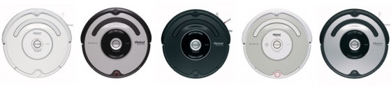
Roomba 500 Series Servicing and Repair Guide Chapter 3: How to Open Up Roomba. Some of the 500 series Roombas are pictured below:
 13 How to Change the IR Bumper Sensor Boards
13.1 Getting Access to the Bumper Sensors
13 How to Change the IR Bumper Sensor Boards
13.1 Getting Access to the Bumper Sensors
Roomba replacement bumper sensor boards can be found at RobotShop.
Before we can change the bumper sensor IR sensor boards, we must first gain access to the bumper sensors themselves. This chapter will explain how to remove the motherboard and associated parts that cover the bumper sensors.
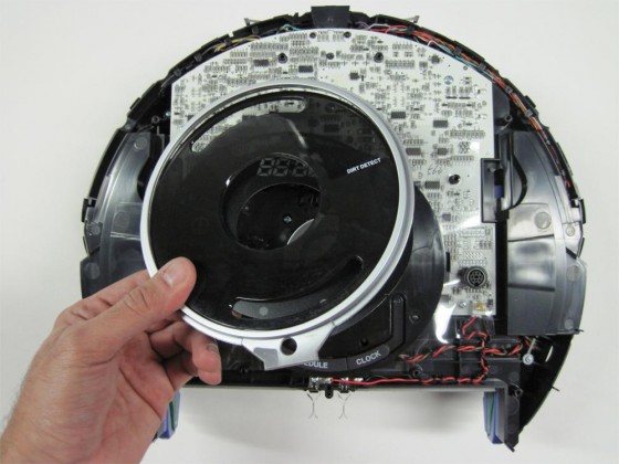
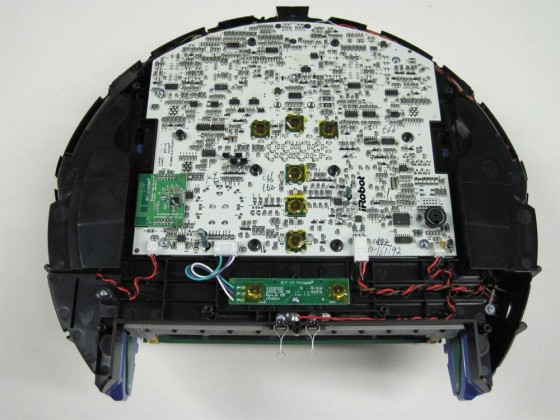
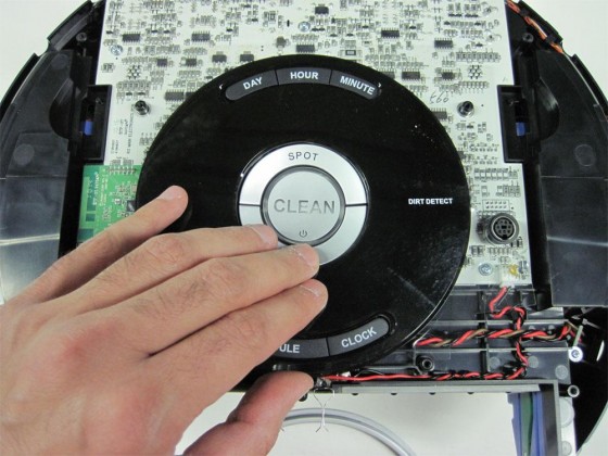
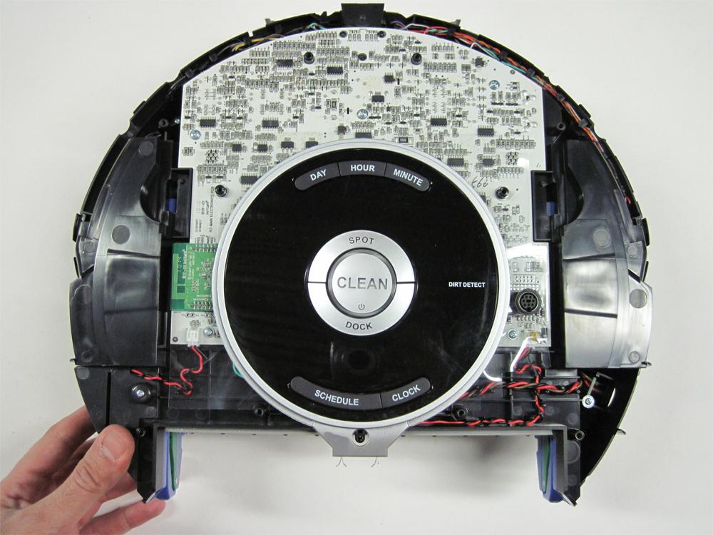
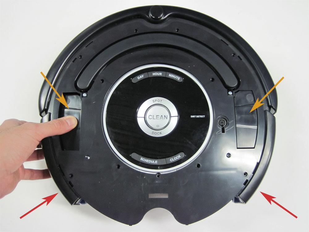
13.1.1 The Roomba will look like this as first.

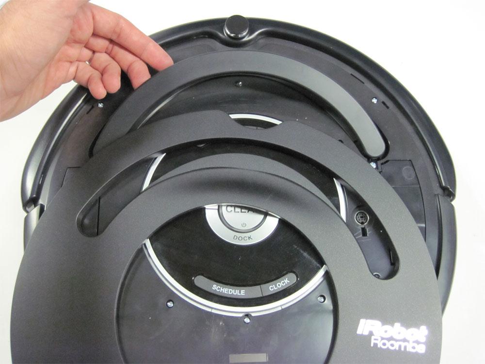
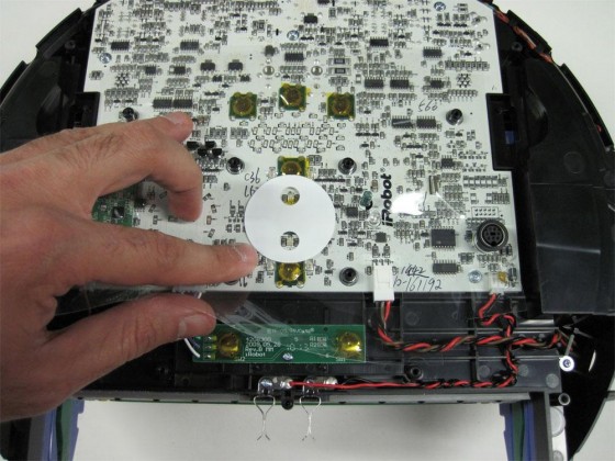
13.1.2 Remove the display bezel set.
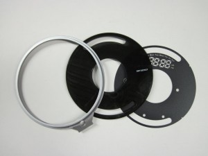
13.1.3 Notice that the display bezel set has three parts that sit one on top of the other, as shown in the picture.
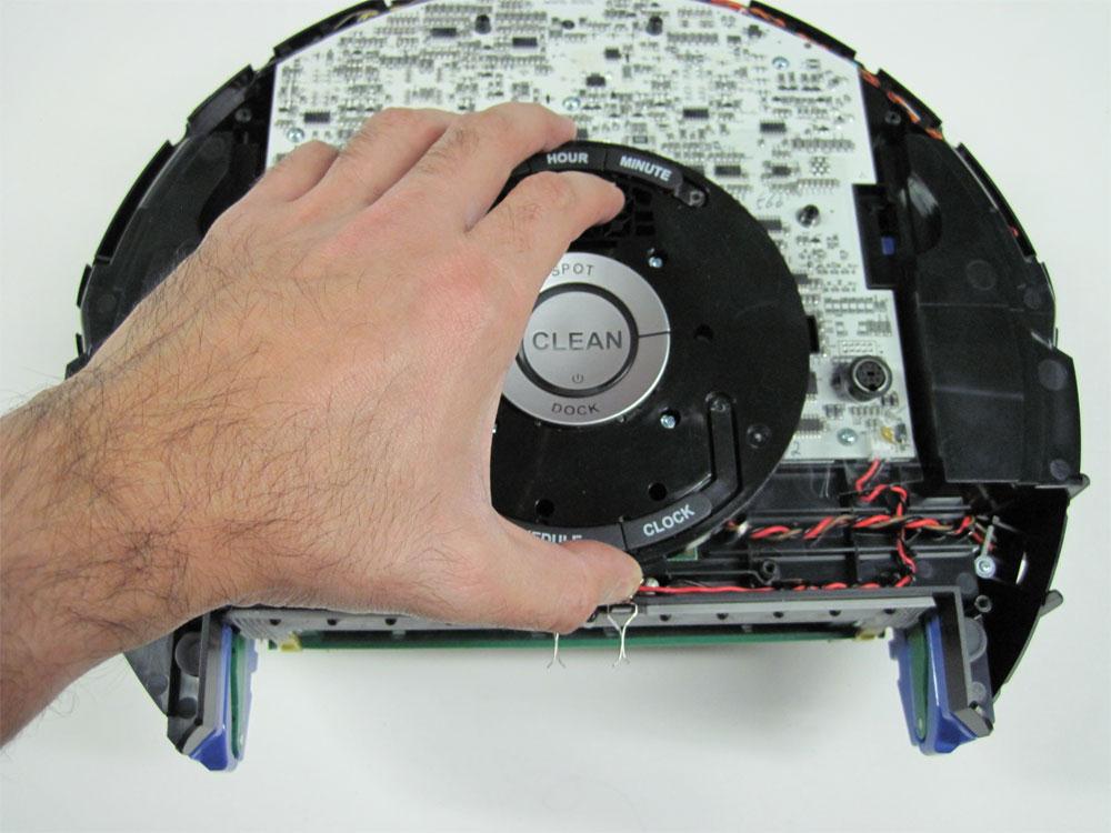
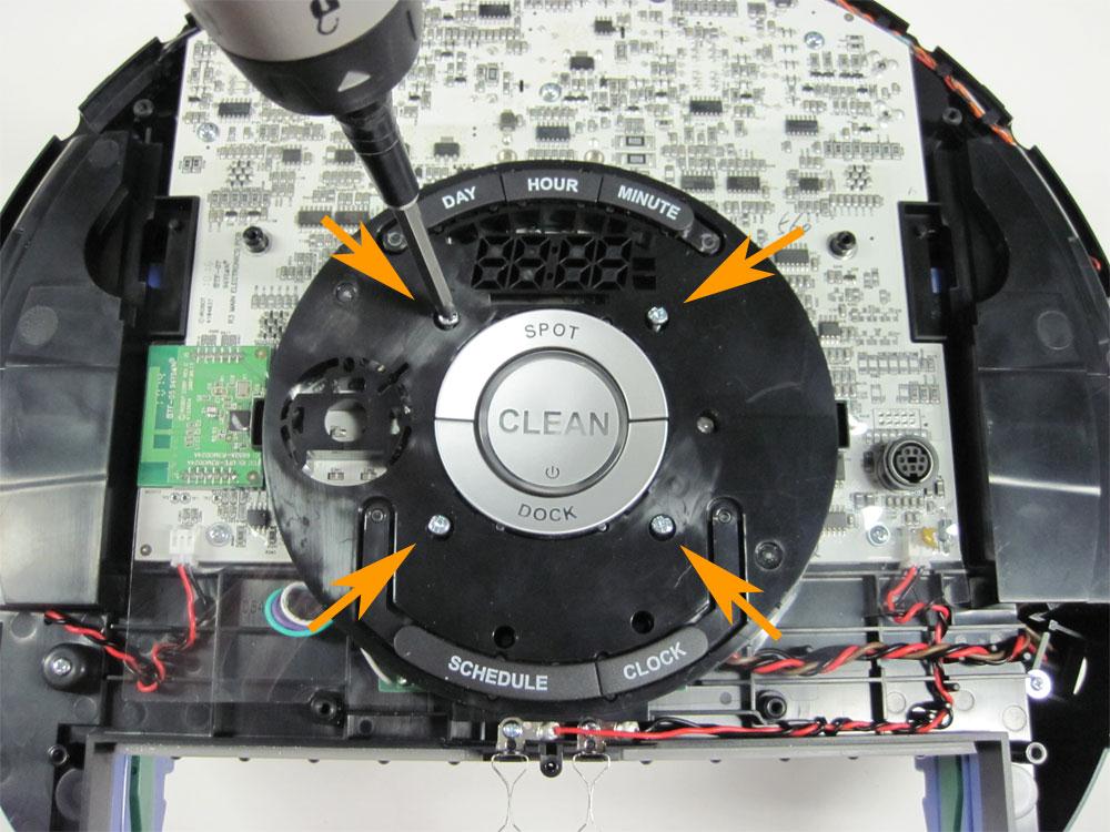
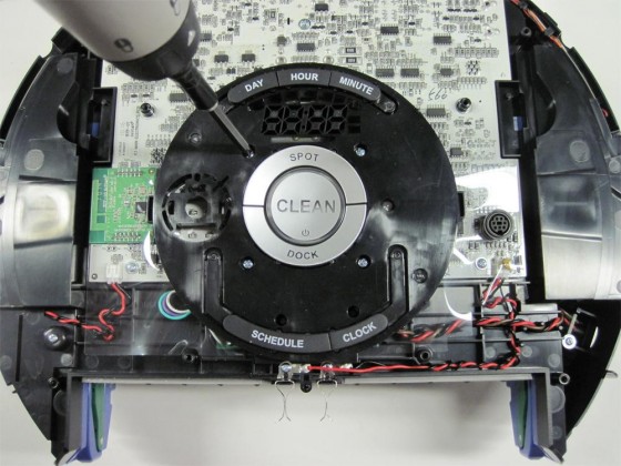
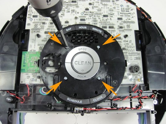
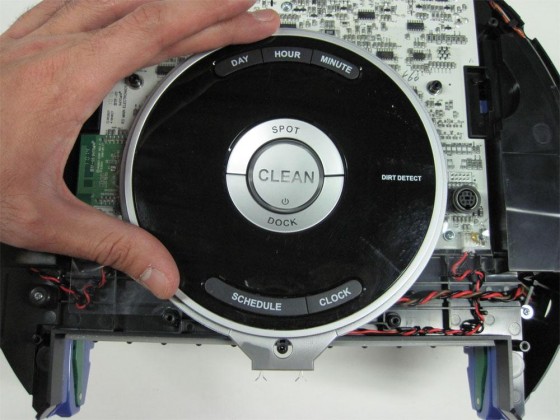
13.1.4 Loosen the four screws holding the control panel in place.
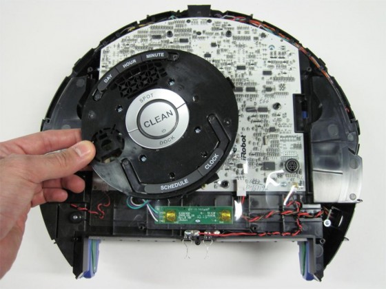
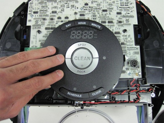
13.1.5 Remove the control panel from the Roomba.
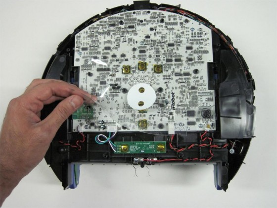
13.1.6 Remove the transparent plastic insulator layer from on top of the Roomba’s motherboard.
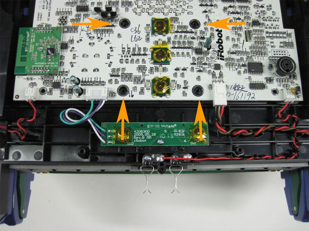
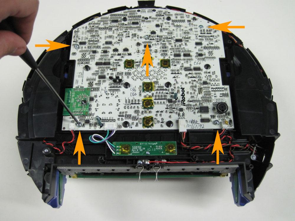
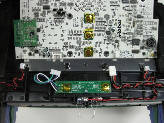
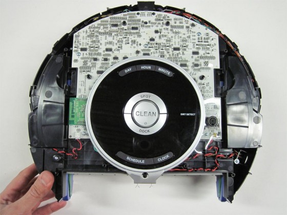
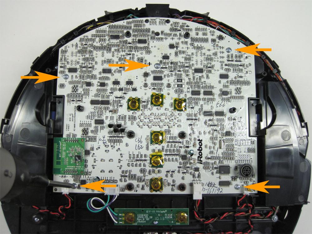
13.1.7 Loosen the five screws holding the motherboard to the Roomba.
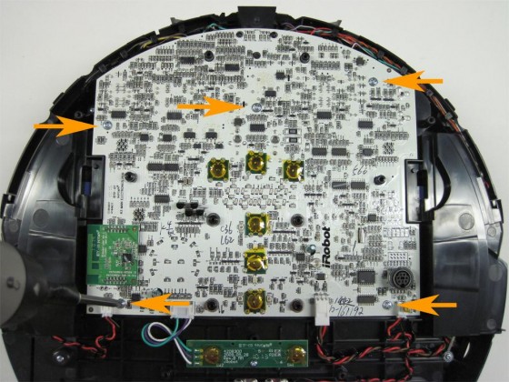
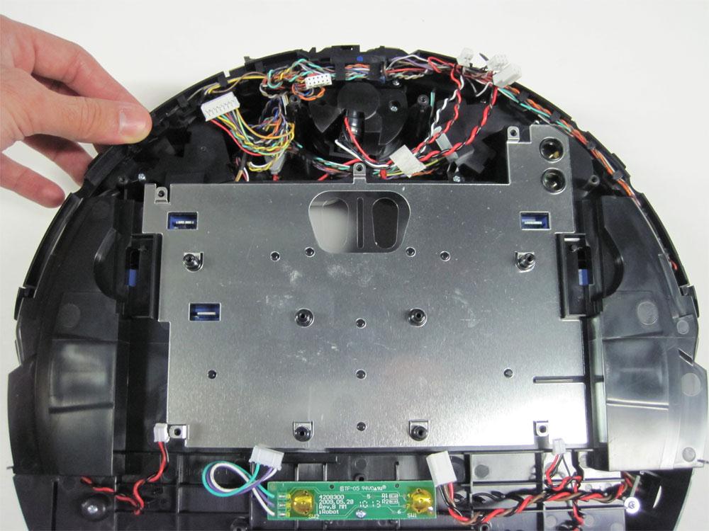
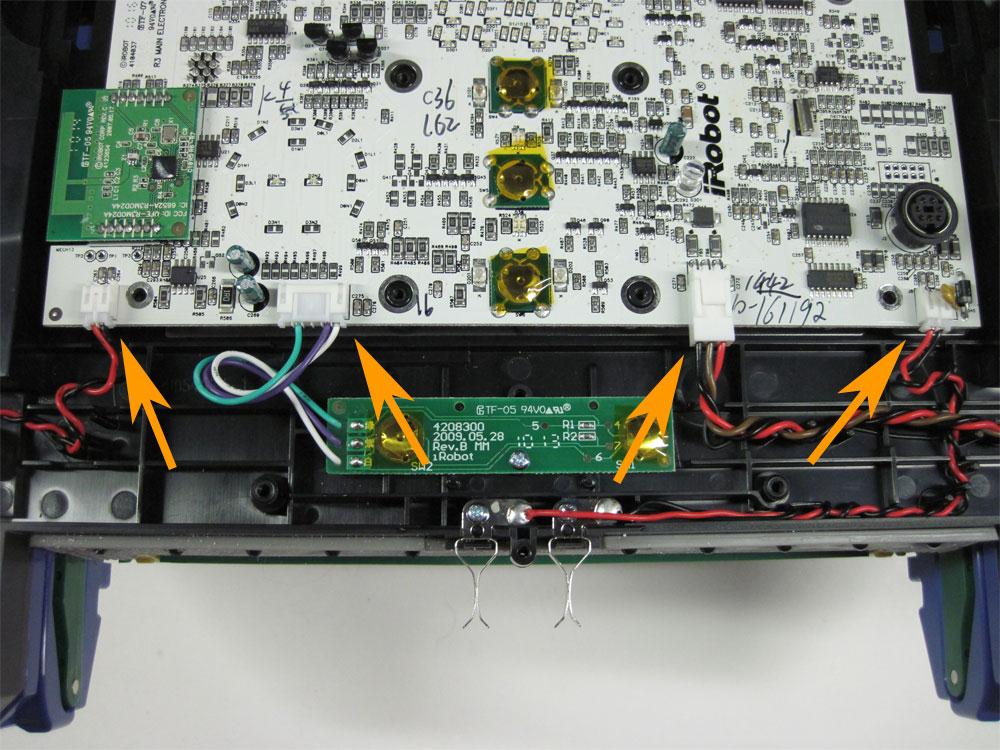
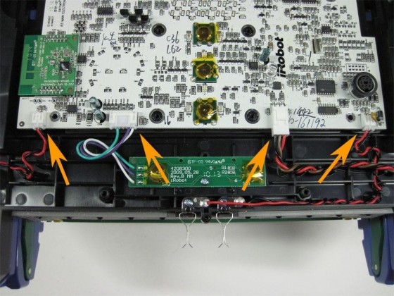
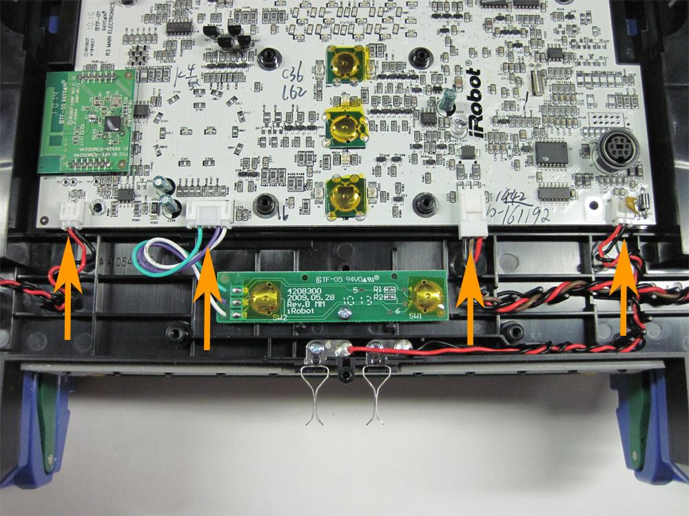
13.1.8 Next, unplug the four connectors at the bottom of the motherboard, shown by the arrows at right.

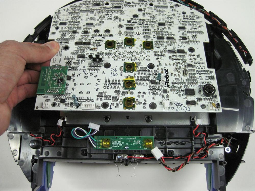
13.1.9 Once the connectors are unplugged, lift the motherboard up from the bottom to loosen it. It will not come out of the Roomba yet, as the top portion must also be disconnected.

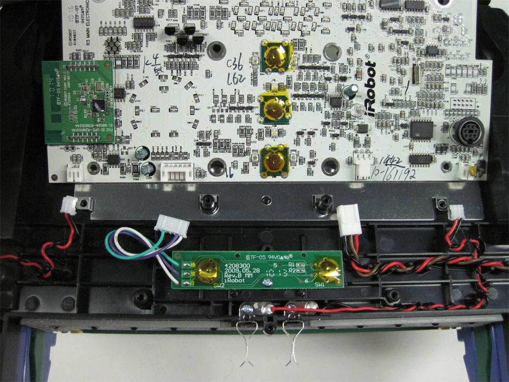
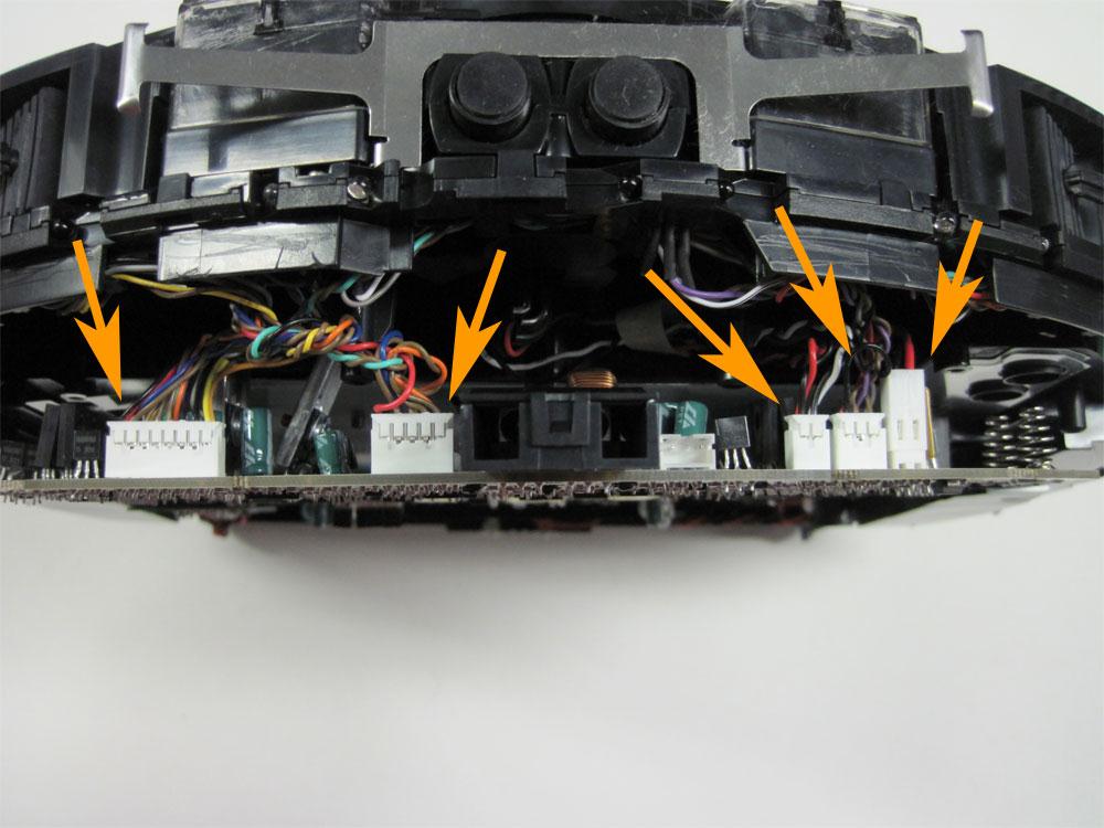
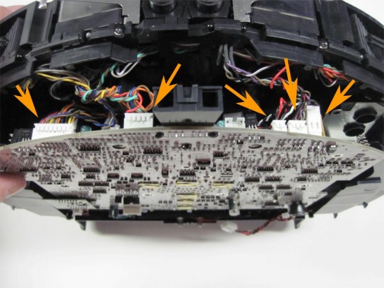
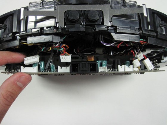
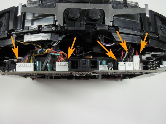
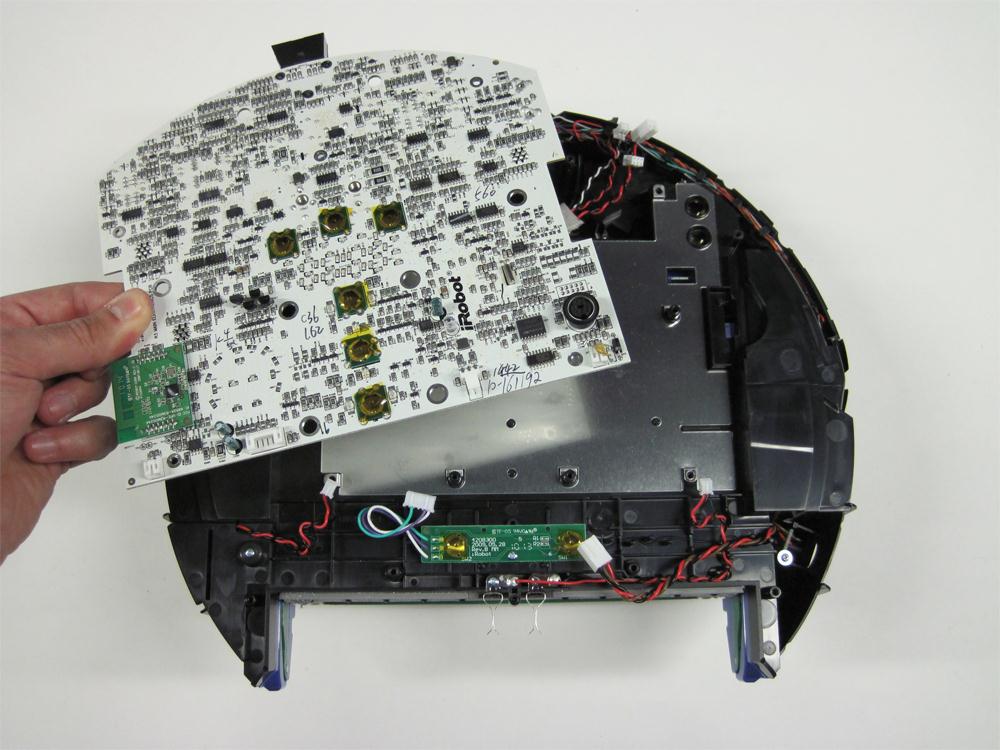
13.1.10 Lift the front end of the motherboard up slightly and disconnect all five connectors from the motherboard.
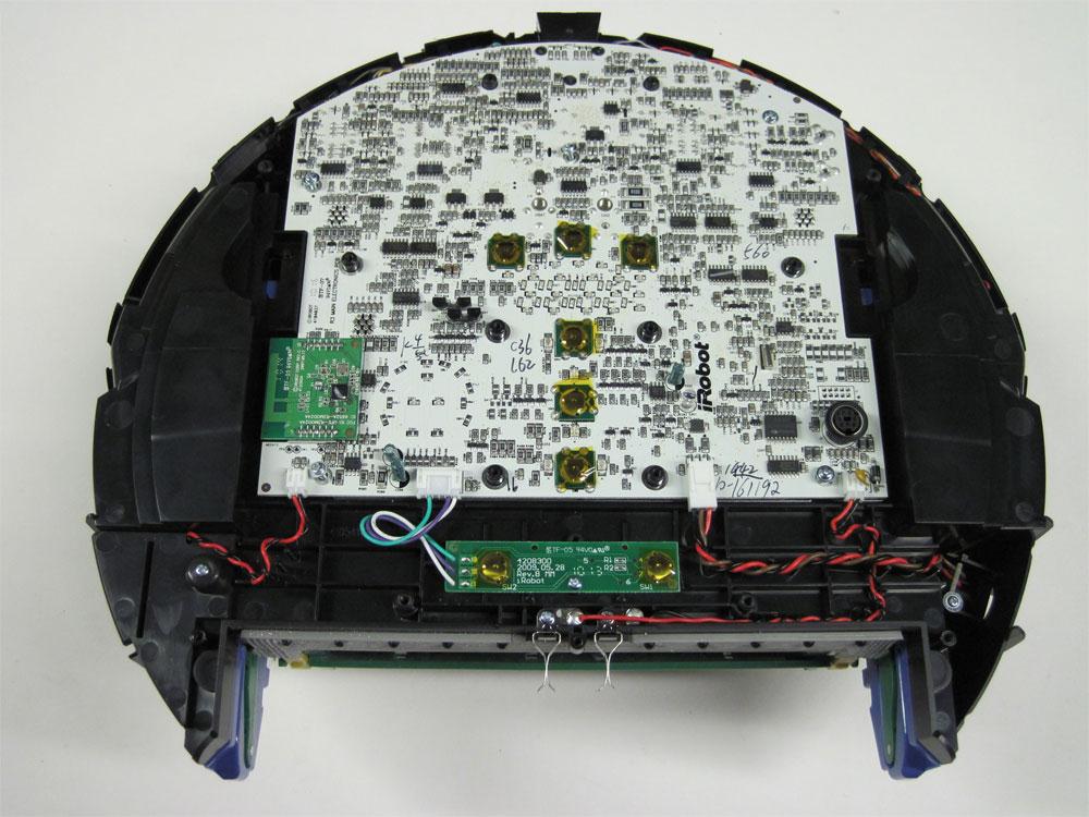
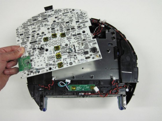
13.1.11 Now remove the motherboard from the Roomba.
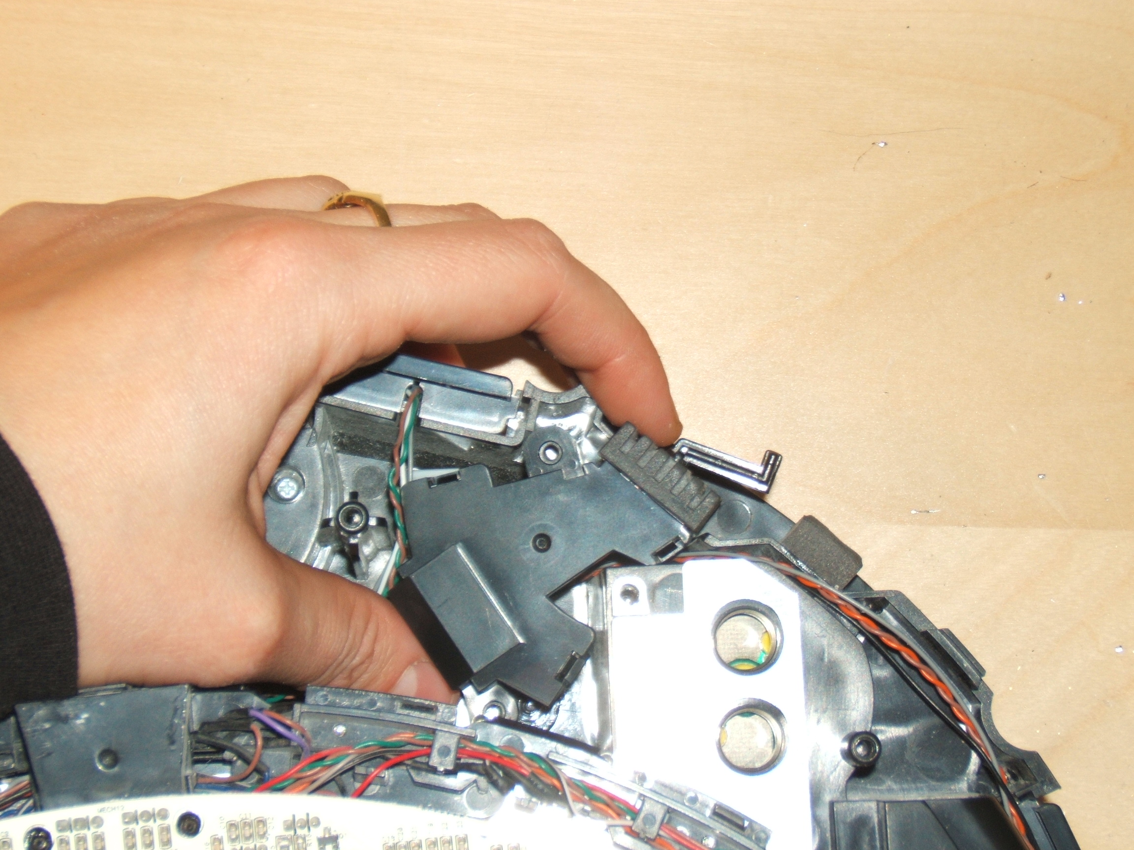
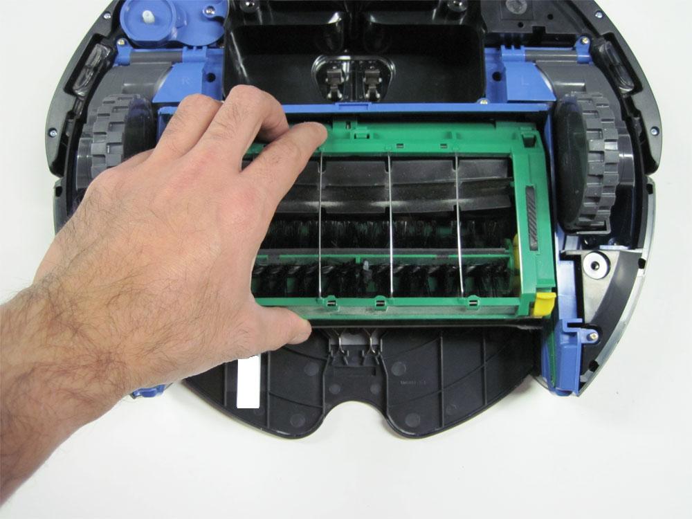
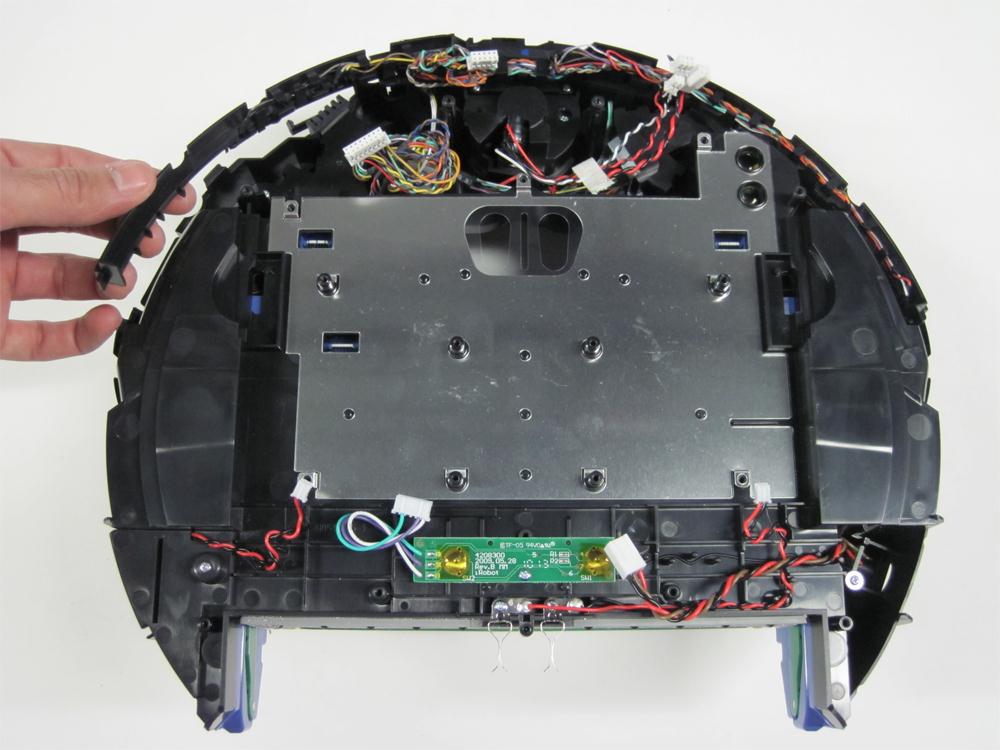
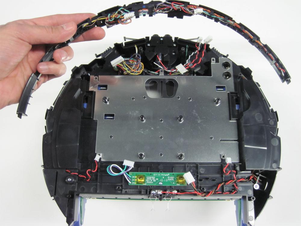
13.1.12 Lift up the light-touch bumper array from either side of the Roomba, as shown in the picture.
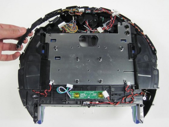
13.1.13 Continue lifting to remove the light-touch bumper array from the Roomba.

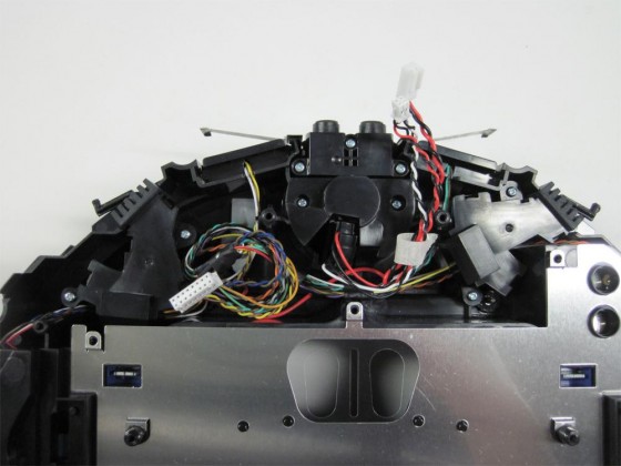
13.1.14 You now have access to your bumper sensors.
13.2 Sensor Parts
Below is an image of the different parts found in the Roomba 500 series bumper sensors. Please refer to this image when the different parts are mentioned within the instructions.
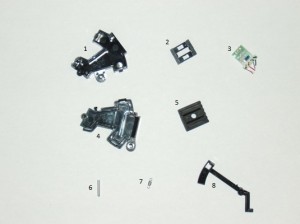
1. Sensor Housing Base
2. Sensor Board Holder
3. Sensor Board
4. Sensor Housing Cover
5. Gasket
6. Lever Pin
7. Spring
8. Lever
13.3 Disassembly of Sensors
Instructions are provided for the replacement of the right bumper sensor. Please note that the same instructions can be used for the replacement of the left bumper sensor also.
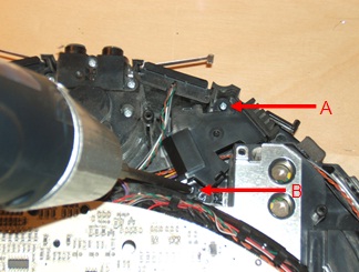
13.3.1 Unscrew the screws A and B.

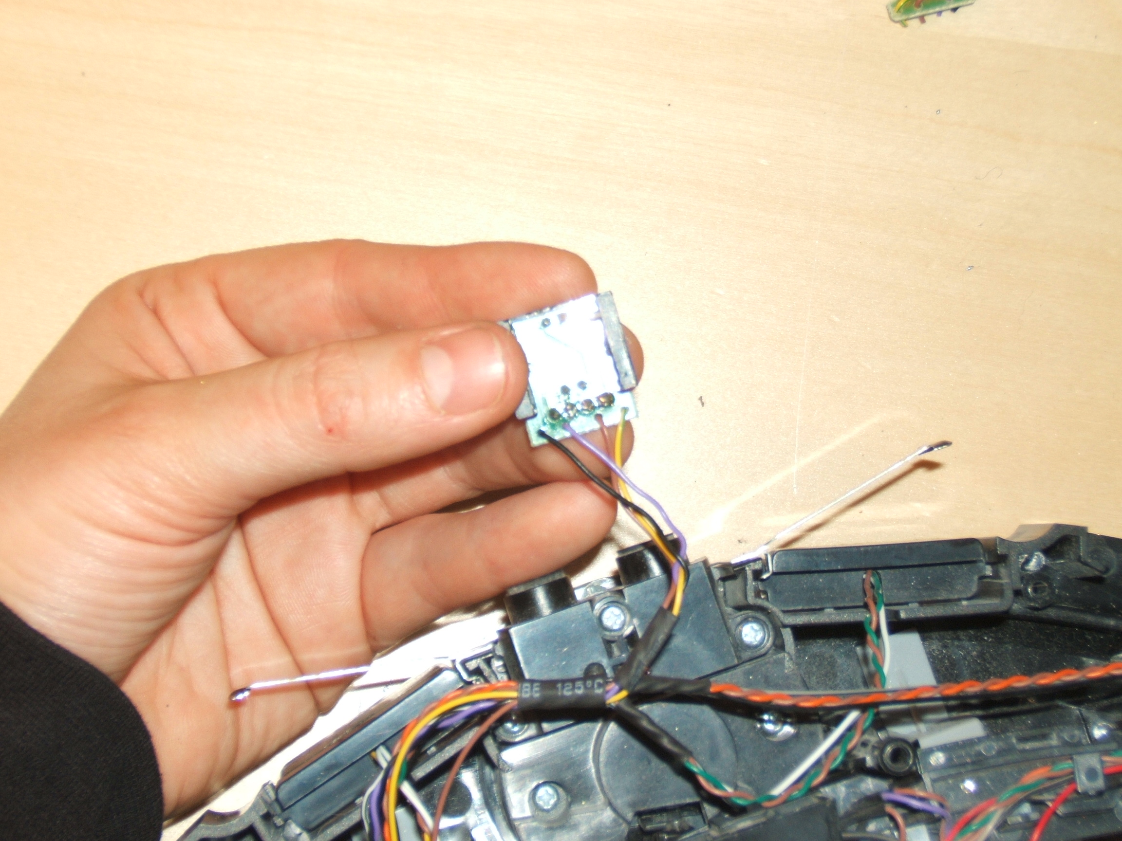
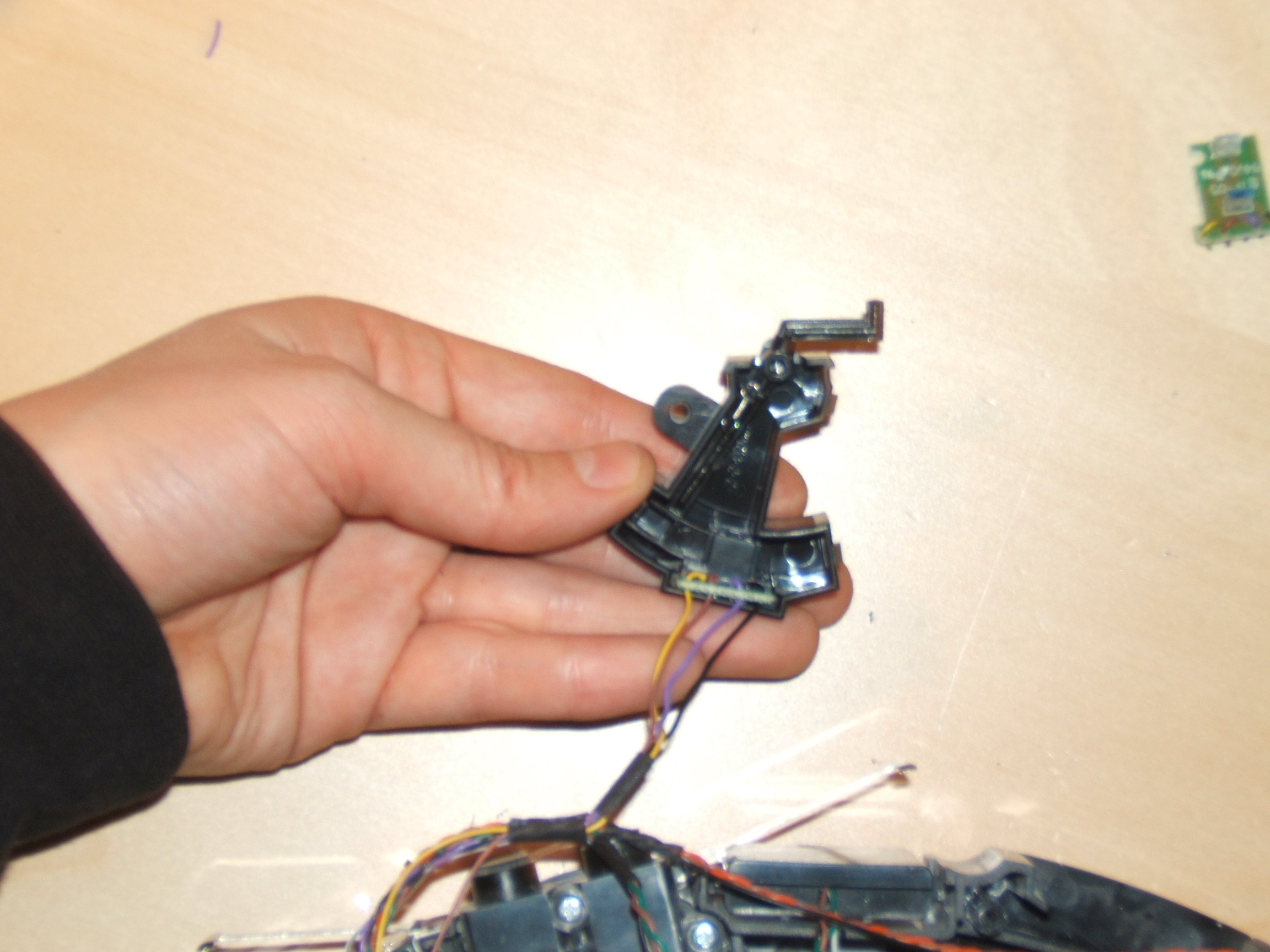
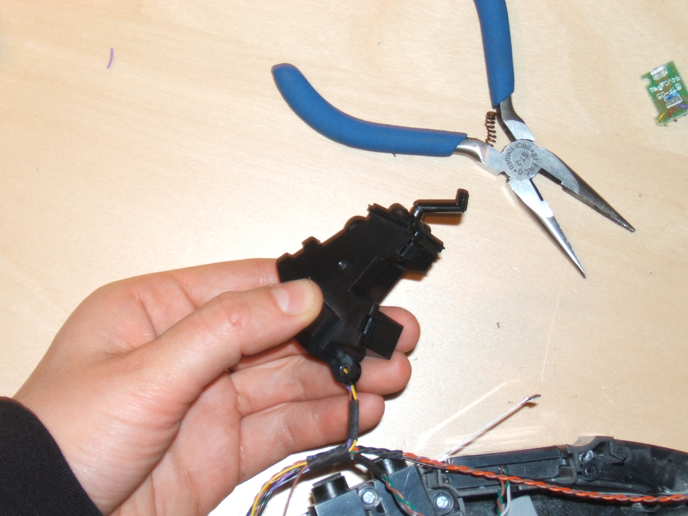
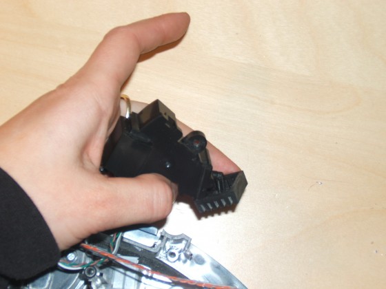
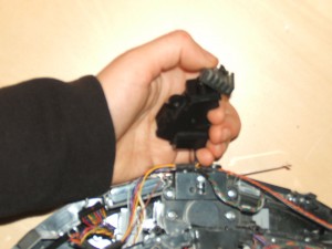
13.3.2 Remove the sensor and its housing from the robot’s frame.

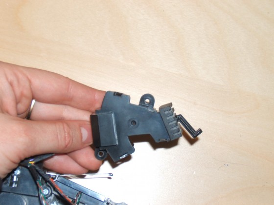
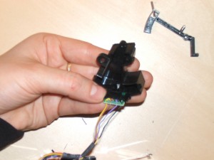
13.3.3 This is how the sensor looks like assembled.
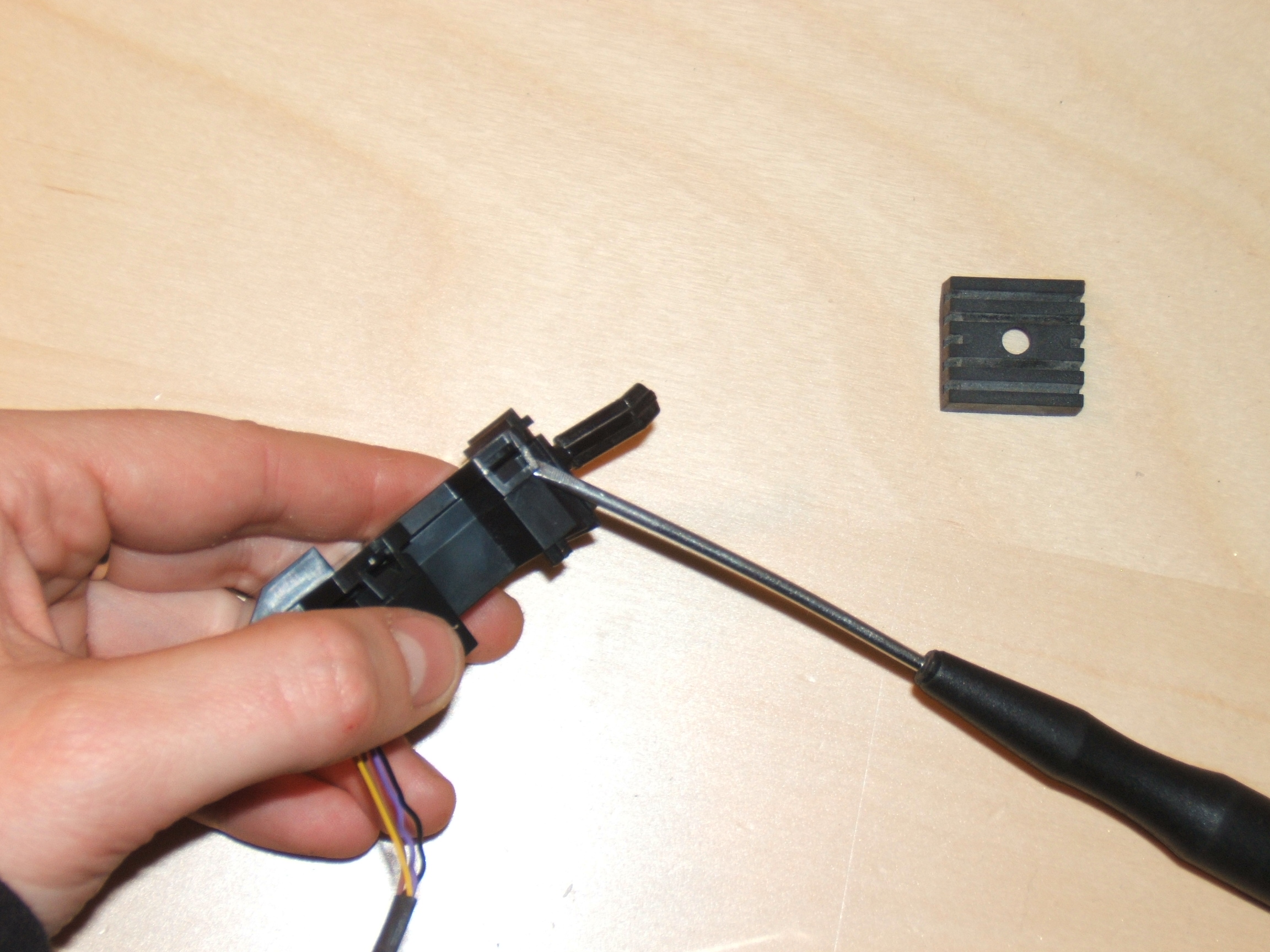
13.3.4 Remove the rubber gasket from the sensor lever.
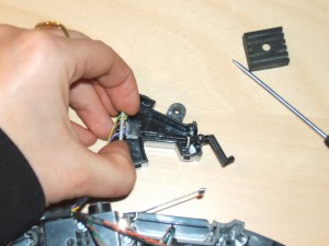
13.3.5 Remove the sensor housing cover. You may use a small flat screwdriver to flex the tabs holding the cover in place.

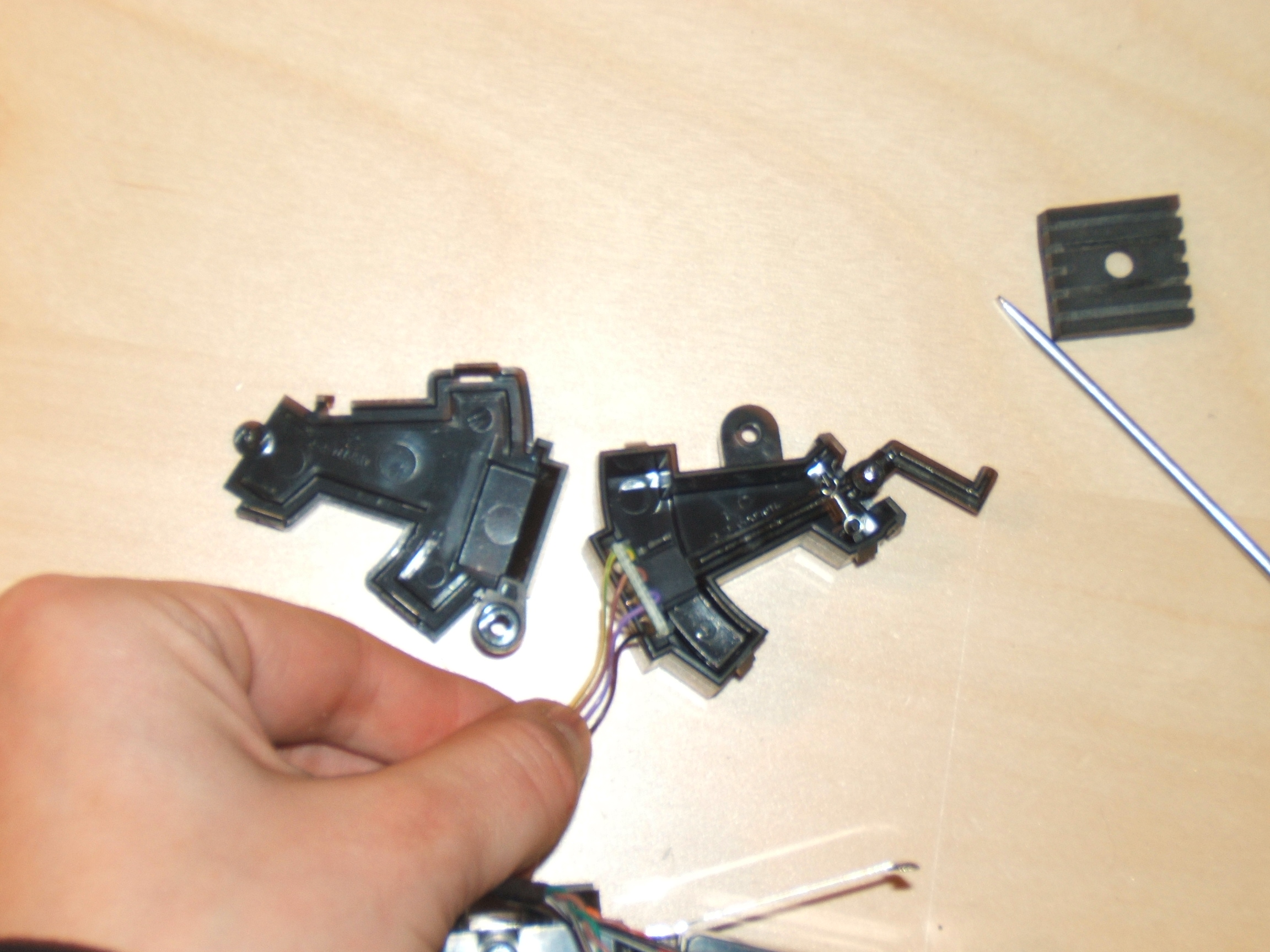
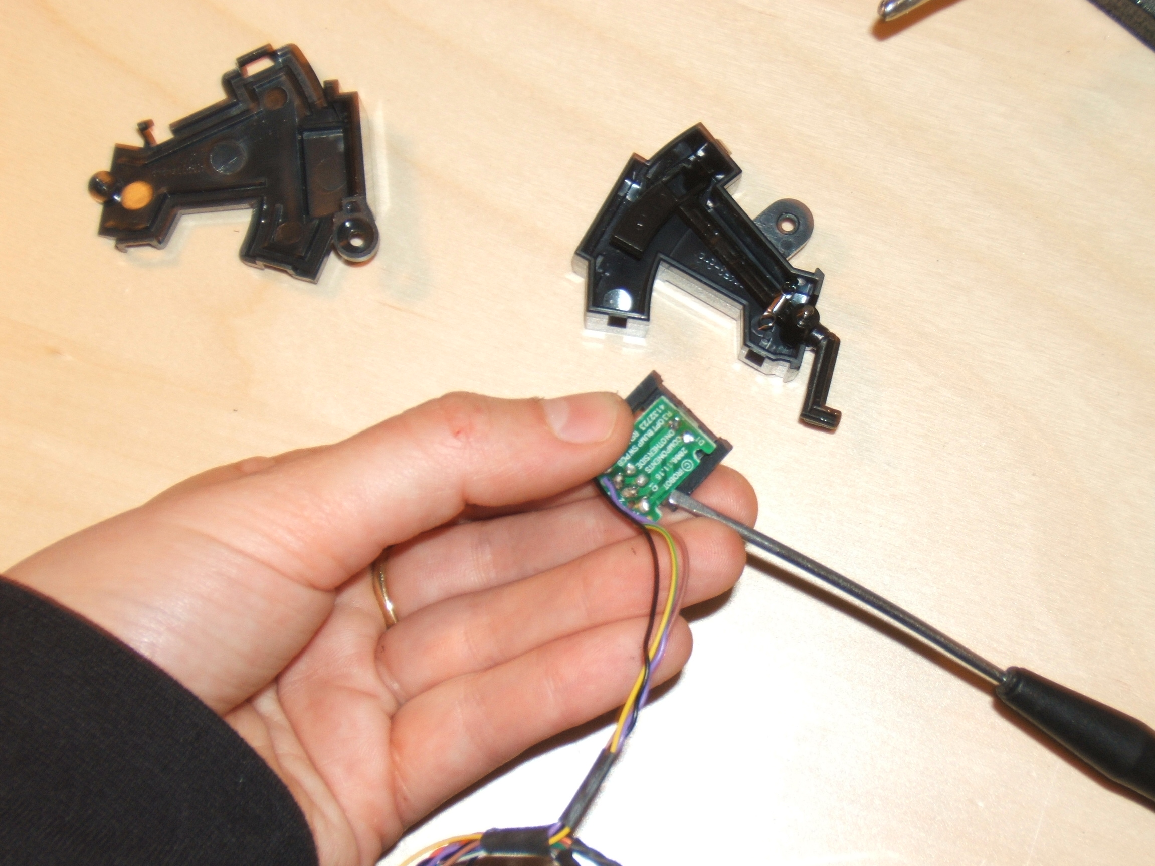
13.3.6 View of the inside of the sensor housing.

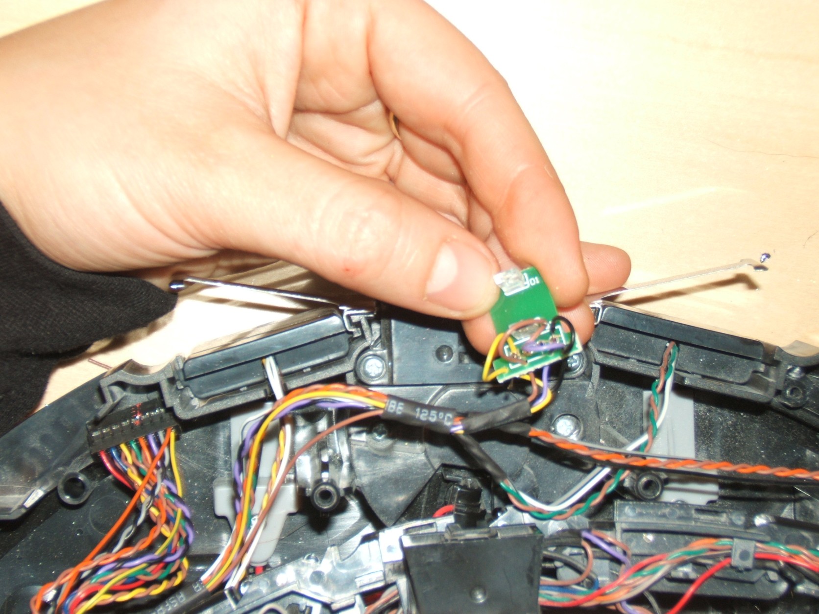
13.3.7 Pull out the sensor board from the housing base.
13.3.8 Take care not to lose the spring and the lever pin as these are very small parts.

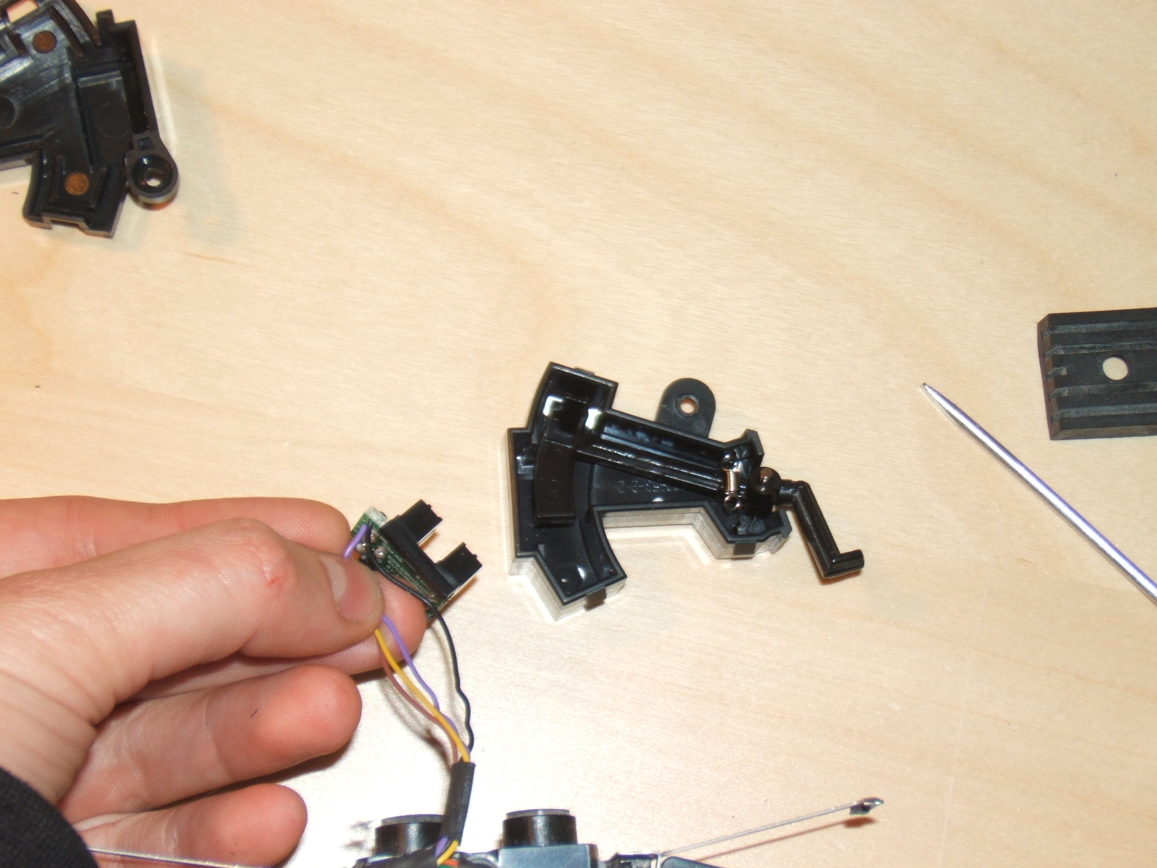
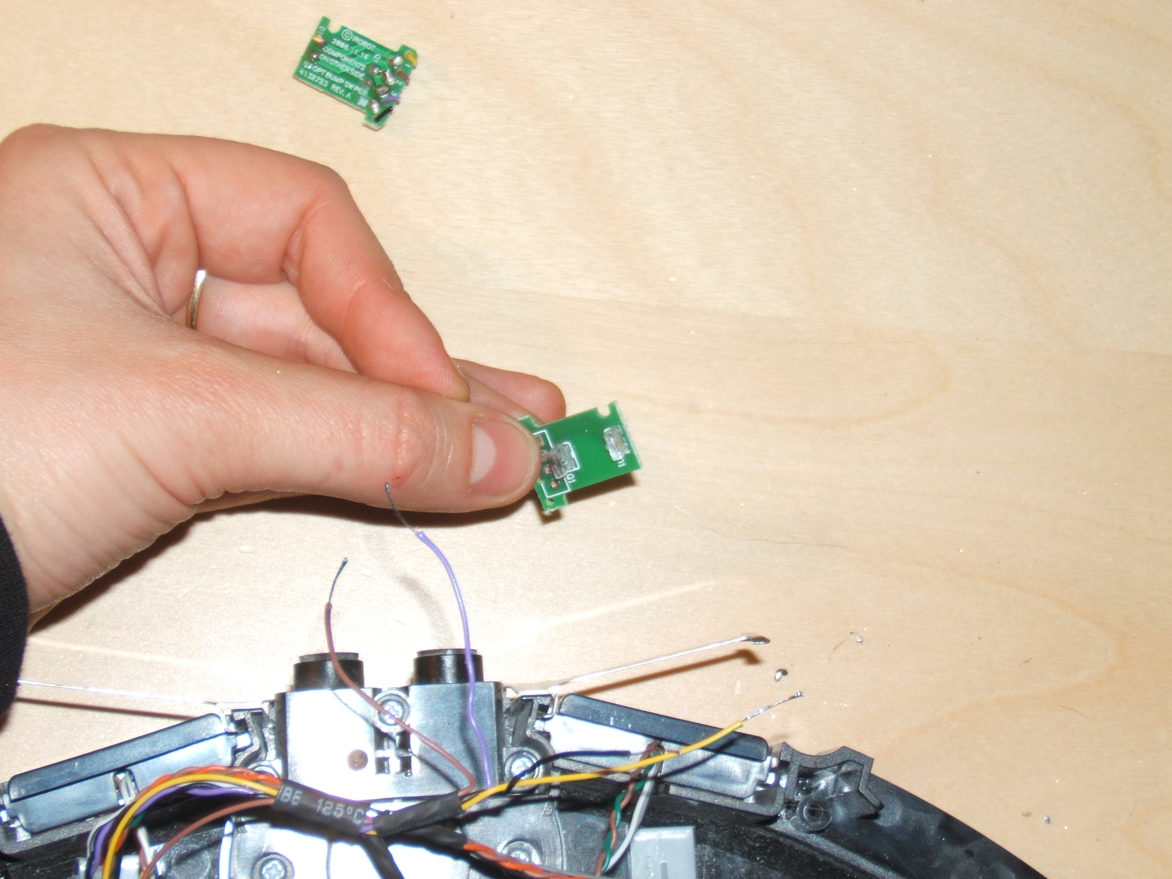
13.3.9 Remove the sensor board from its holder. You may use a small flat screwdriver in order to gently lift the circuit board on both sides.
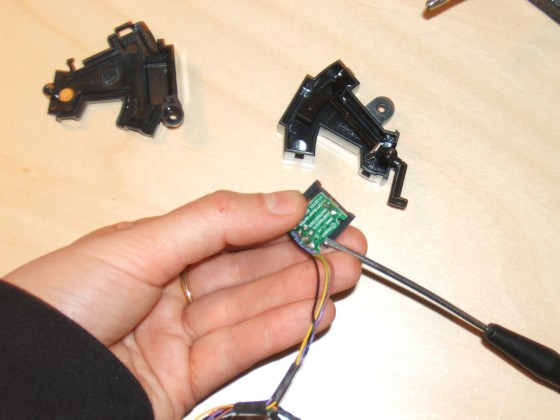
13.3.10 You are now ready to replace the sensor board.
13.4 Replacement of Sensor Board
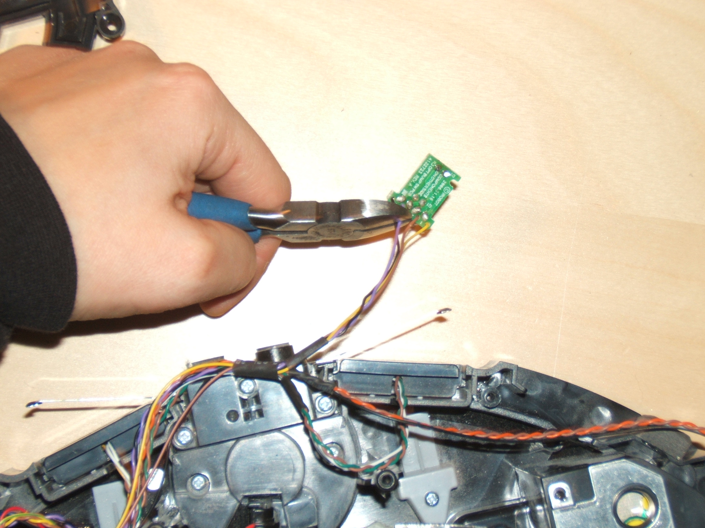
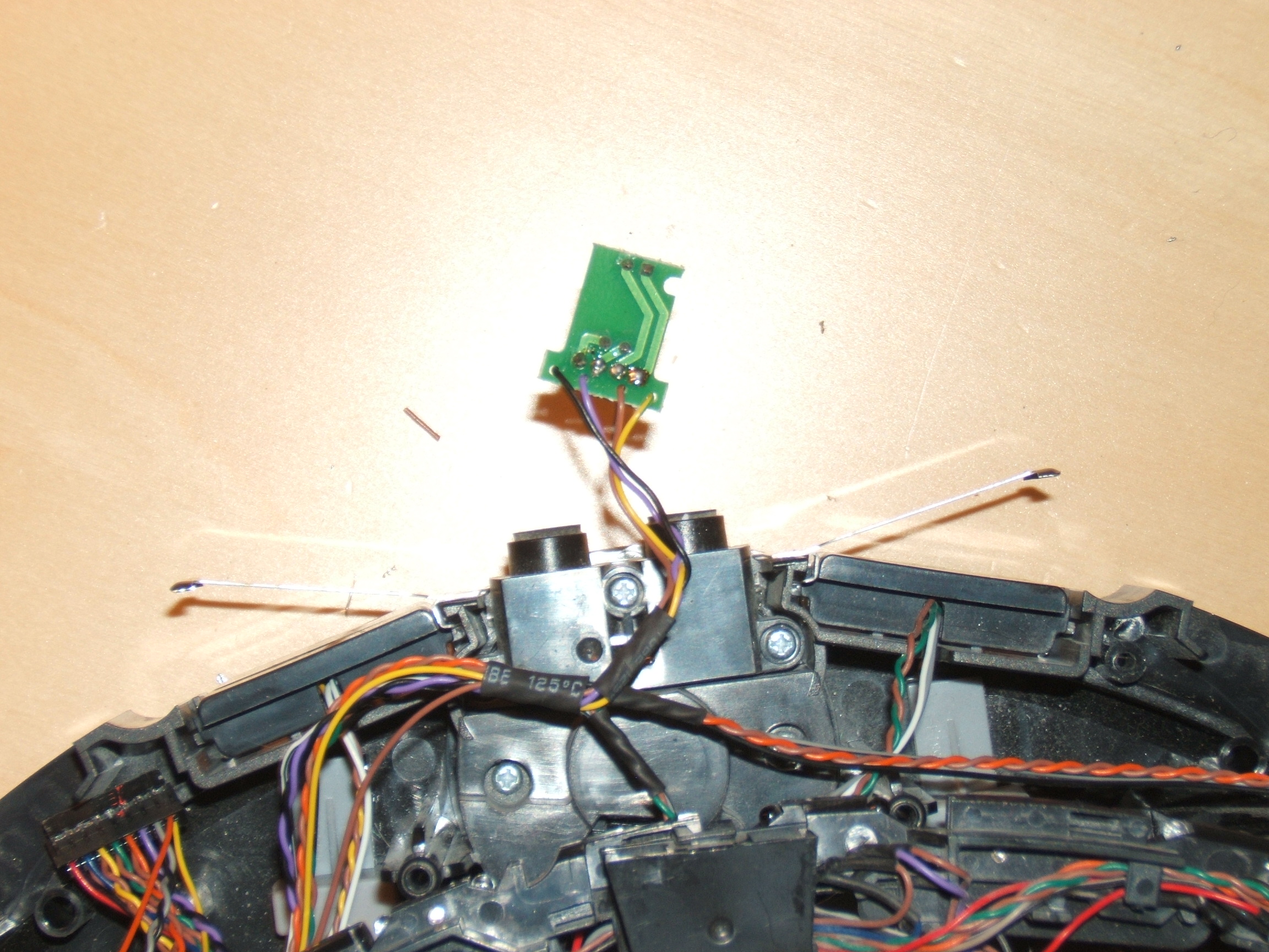
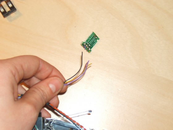
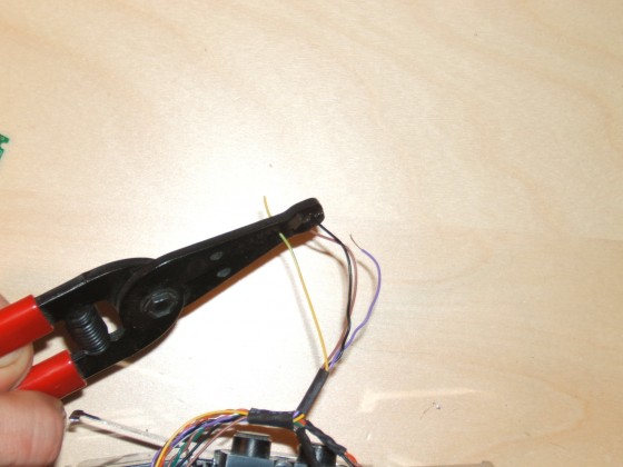
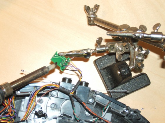
13.4.1 With small wirecutters, cut the four wires to the defective board. Leave small lengths of wire as a color reference.

13.4.2 You will then need to strip off the ends of each wire that will be connecting to the new sensor board.
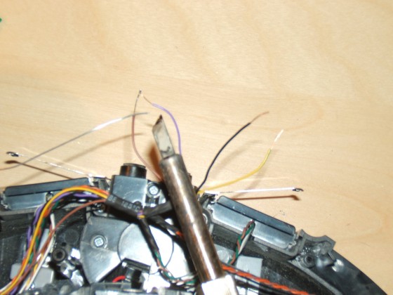
13.4.3 Although not mandatory, we suggest tinning the wire ends that have been stripped off. Doing this will make it easier to insert the wires into the holes found on the new sensor board.
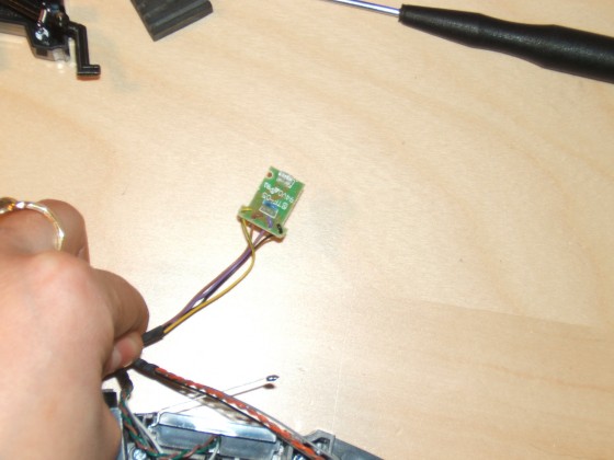
13.4.4 You can now unwrap your new sensor from its packaging.

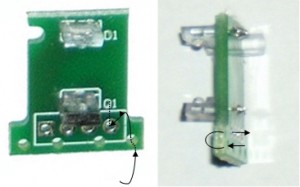
13.4.5 Next, you will need to insert the wires into their respective holes found on the end of the board. Right side up (looking at the LEDs) you will place the wires in the following order from left to right: yellow, brown, purple and black for the right sensor, and white, red, grey, and black for the left sensor. Note that in some cases the wires could be of a different color. In this case, please refer to the defective sensor that you have removed. You will then need to bend the wires for them to insert in the proper mounting holes. Note that the wires should be soldered from the back side of the board.

13.4.6 Refer to this picture for the insertion of the wires into the circuit board.
- Dotted lines are behind the circuit board.
- Solid lines are in front of the circuit board.
Wires must be soldered in the back of the sensor board.
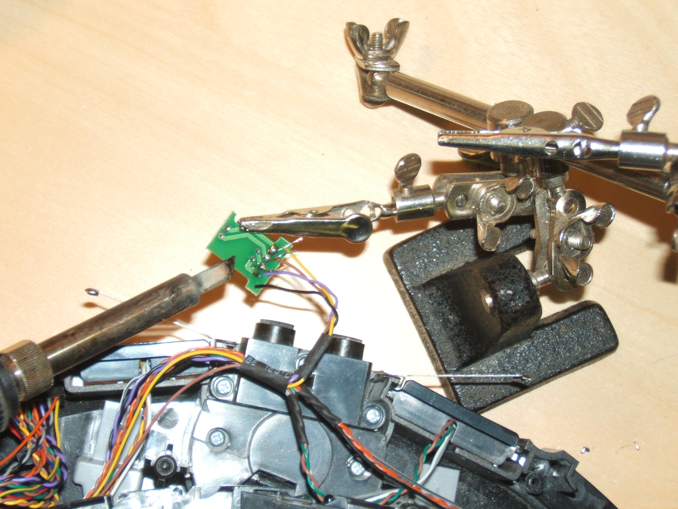
13.4.7 You may then flip the board over and solder the four wires onto the board.
13.4.8 Once the wires are properly soldered, you are ready to put the sensor and its housing back together.

13.5 Reassembly of Sensor
13.5.1 Insert the sensor board into its holder. There is a carved semi-circle indicating the correct way the board should be inserted.

13.5.2 You may then insert the sensor board and holder halfway into the housing base.
13.5.3 The reason that you only insert the board halfway is that you then need to insert the lever that will act as the barrier for the LEDs. There is only one way to insert the arm. It must insert between the two LEDs and over the pin found at the other end.

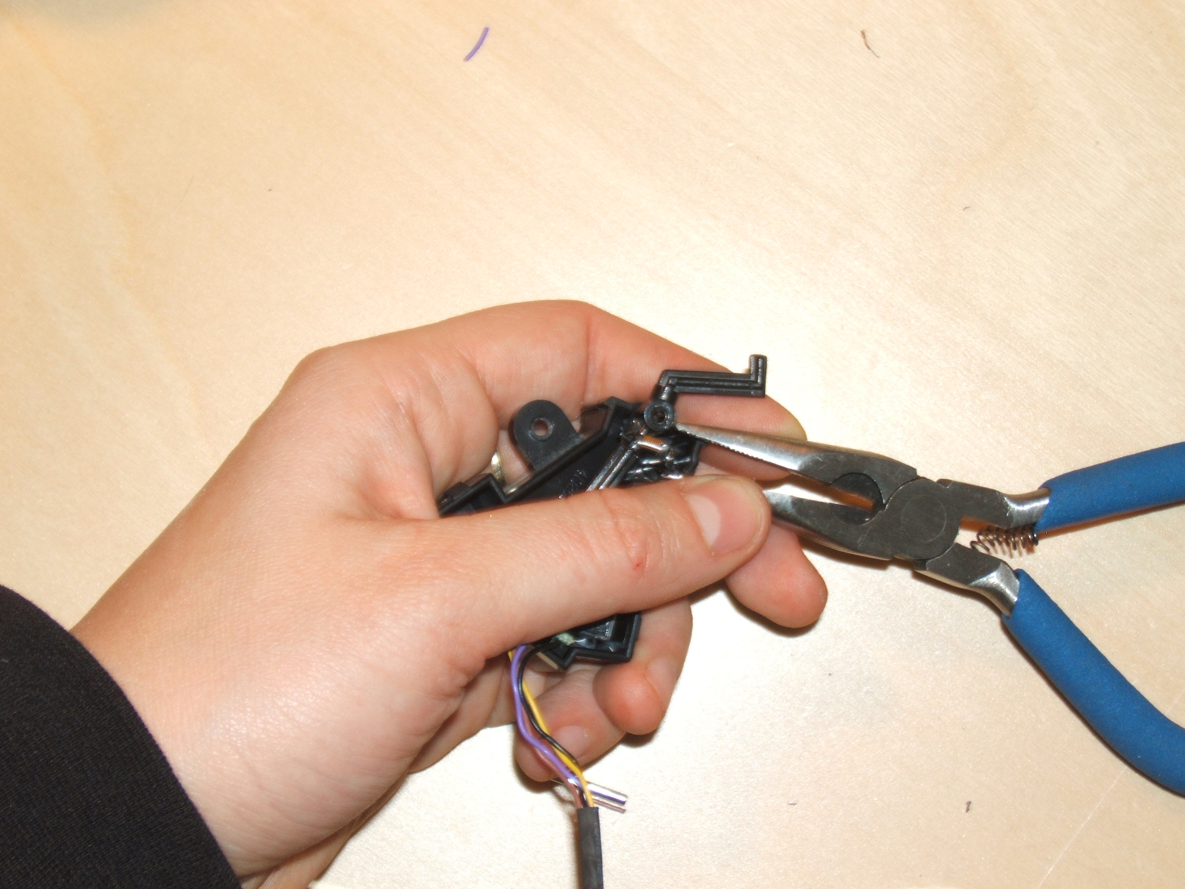
13.5.4 You will then need to install the spring that is needed for the lever to move. It is easier to install the spring on one side first (usually the side that has a small hook). You can then easily take a pair of long nose pliers to pull on the spring and insert it on the ring on the holder on the other side of the housing base.

13.5.5 You may then place the sensor housing cover back on. It should simply snap into place.

13.5.6 Next, you can place the rubber gasket back onto the lever. Take care to place it the correct way, as shown in the image. The arm will not move properly if it is placed the other way around.
13.5.7 Place the sensor back into the Roomba frame. Do not forget to screw the sensor housing back in place.
13.6 Reinstalling the Motherboard and Display
13.6.1 Reinstall the light-touch bumper removed previously.

13.6.2 Reinstall the motherboard, starting at the bottom. Line up the motherboard with the four bottom connections.
13.6.3 Reconnect the four connectors, as shown by the orange arrows.
13.6.4 Line up the board so that the four holes pictured are aligned with the four corresponding posts on the Roomba’s frame underneath. This will help you with the next step.

13.6.5 Stand the Roomba on end to make connecting the top of the motherboard easier.
13.6.6 Reconnect the five connections shown by the orange arrows. The connections can only go in one place each.
13.6.7 With all the connectors properly connected, push the motherboard down into place.
13.6.8 Place the five motherboard screws in place and tighten them down. Do not use an electric screwdriver as these threads are plastic and particularly delicate.

13.6.9 Place the transparent plastic insulator back over the motherboard.
13.6.10 Place the control panel on the motherboard, careful to line up the four screws with the four threaded posts underneath.

13.6.11 Tighten the control panel’s four screws in place.
13.6.12 Place the first layer of the control panel display as shown in the picture.
13.6.13 Put back the control panel display cover, making sure the orientation is correct.
13.6.14 Place the control panel display trim around the cover, making sure the screw hole is at the bottom.
13.6.15 You now have successfully replaced your Roomba’s bumper sensor.
For details on how to reassemble the Roomba’s frame, please see the
Roomba 500 Series Servicing and Repair Guide Chapter 3: How to Open Up Roomba.
For addition help contact the RobotShop Technical Team via our
Online Support Center.
Roomba replacement parts can be found at RobotShop.


 13 How to Change the IR Bumper Sensor Boards
13.1 Getting Access to the Bumper Sensors
Roomba replacement bumper sensor boards can be found at RobotShop.
Before we can change the bumper sensor IR sensor boards, we must first gain access to the bumper sensors themselves. This chapter will explain how to remove the motherboard and associated parts that cover the bumper sensors.
13.1.1 The Roomba will look like this as first.
13 How to Change the IR Bumper Sensor Boards
13.1 Getting Access to the Bumper Sensors
Roomba replacement bumper sensor boards can be found at RobotShop.
Before we can change the bumper sensor IR sensor boards, we must first gain access to the bumper sensors themselves. This chapter will explain how to remove the motherboard and associated parts that cover the bumper sensors.
13.1.1 The Roomba will look like this as first.

 13.1.4 Loosen the four screws holding the control panel in place.


 1. Sensor Housing Base
2. Sensor Board Holder
3. Sensor Board
4. Sensor Housing Cover
5. Gasket
6. Lever Pin
7. Spring
8. Lever
13.3 Disassembly of Sensors
Instructions are provided for the replacement of the right bumper sensor. Please note that the same instructions can be used for the replacement of the left bumper sensor also.
13.3.1 Unscrew the screws A and B.
1. Sensor Housing Base
2. Sensor Board Holder
3. Sensor Board
4. Sensor Housing Cover
5. Gasket
6. Lever Pin
7. Spring
8. Lever
13.3 Disassembly of Sensors
Instructions are provided for the replacement of the right bumper sensor. Please note that the same instructions can be used for the replacement of the left bumper sensor also.
13.3.1 Unscrew the screws A and B.