

Building an Infrared Remote Decoder


Craig Gardner shows you how to build an infrared remote decoder - control your robot with a TV remote!
Adding a form of remote control to your robot can be fun but radio can sometimes be over kill. Infrared such as used for your TV, VCR and other equipment is a simple way to add control to a project and can be used to control your robot or as a wireless keypad to enter parameters and you can get universal remotes for as little as $5.
 You will need the following parts for the receiver.
1 PIC12F675 or PIC12F629
1 PNA4612M
2 .1uf capacitors
2 390 ohm resistors
1 LED
The circuit is very straight forward and can be built point to point on perfboard or you can etch a board with the artwork provided. The pdf of the board has 4 boards side by side each board is very compact and it is easy to etch your own using the toner transfer method.
You will need the following parts for the receiver.
1 PIC12F675 or PIC12F629
1 PNA4612M
2 .1uf capacitors
2 390 ohm resistors
1 LED
The circuit is very straight forward and can be built point to point on perfboard or you can etch a board with the artwork provided. The pdf of the board has 4 boards side by side each board is very compact and it is easy to etch your own using the toner transfer method.
 Infrared remotes send out a stream of pulses of different lengths to indicate a start bit then data bits the decoder described decodes Sony IR remotes which are based on a pulse code signal coding which have a start bit of about 2200 us then 12 data bits the first 5 are the device data bits such as TV, VCR, etc. the next 7 are the command bits. A logic 0 is about 550 us and a logic 1 is 1100 us.
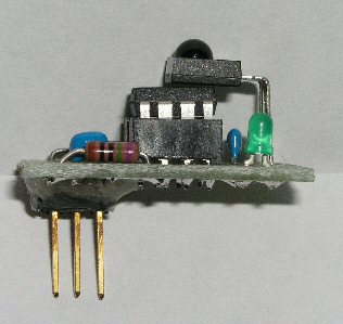
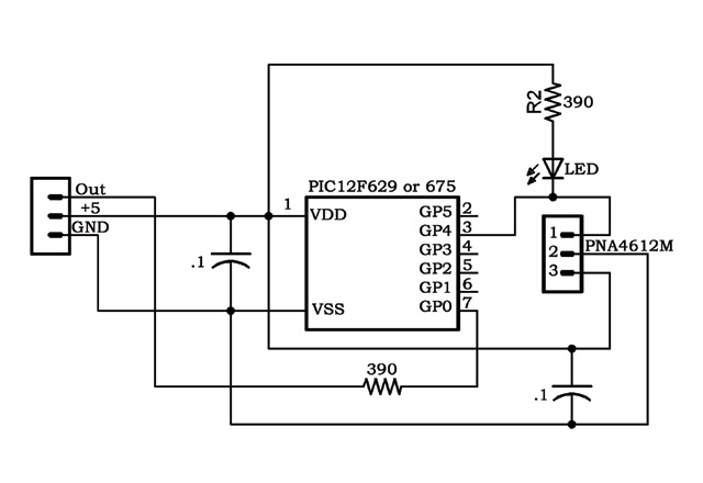
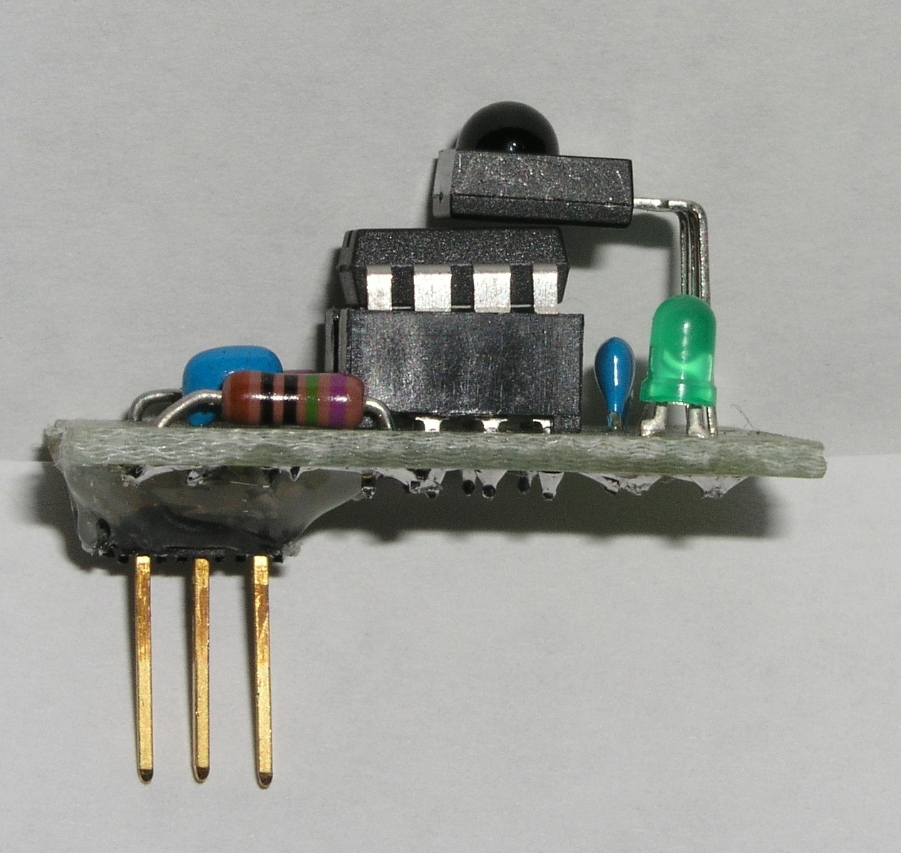
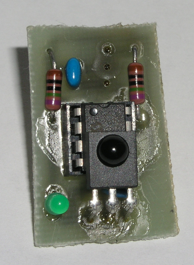
The circuit uses a Microchip PIC12F675 or PIC12F629 the main difference between the chips is that the PIC12F675 has 4 channels of 10 bit A/D. Pin 3 GPIO.4 of the PIC is connected to a PNA4612M module which sets the output pin low when it receives a 38khz modulated infrared signal there is also a resistor and LED connected from +5 to the output pin so you can see it flash on as the module receives data, these 2 parts can be left out if you want. There is a resistor on the serial output pin 7 GPIO.0 which is there to limit current as a precaution. The circuit only requires 3 pins to your microcontroller GND, +5 volts, serial out you can use your choice of connectors or just wires. When mounting the PNA4612M I leave the leads long and bend it over so that it points up making it easier to receive the IR signal. After soldering the connector on the bottom I use hot glue to add a little extra mechanical strength so the connector won't bend over easy.
Infrared remotes send out a stream of pulses of different lengths to indicate a start bit then data bits the decoder described decodes Sony IR remotes which are based on a pulse code signal coding which have a start bit of about 2200 us then 12 data bits the first 5 are the device data bits such as TV, VCR, etc. the next 7 are the command bits. A logic 0 is about 550 us and a logic 1 is 1100 us.
The circuit uses a Microchip PIC12F675 or PIC12F629 the main difference between the chips is that the PIC12F675 has 4 channels of 10 bit A/D. Pin 3 GPIO.4 of the PIC is connected to a PNA4612M module which sets the output pin low when it receives a 38khz modulated infrared signal there is also a resistor and LED connected from +5 to the output pin so you can see it flash on as the module receives data, these 2 parts can be left out if you want. There is a resistor on the serial output pin 7 GPIO.0 which is there to limit current as a precaution. The circuit only requires 3 pins to your microcontroller GND, +5 volts, serial out you can use your choice of connectors or just wires. When mounting the PNA4612M I leave the leads long and bend it over so that it points up making it easier to receive the IR signal. After soldering the connector on the bottom I use hot glue to add a little extra mechanical strength so the connector won't bend over easy.
 The program was written using ME Labs Pic Basic Pro and is small and straight forward. The program gets the 7 command bits and 1 device bit and sends it out serially at 9600 baud inverted then waits for the next command. A step by step of the program flow is:
Set fuse settings and control registers since we don't need A/D or Comparators we turn them off.
The program was written using ME Labs Pic Basic Pro and is small and straight forward. The program gets the 7 command bits and 1 device bit and sends it out serially at 9600 baud inverted then waits for the next command. A step by step of the program flow is:
Set fuse settings and control registers since we don't need A/D or Comparators we turn them off.

 Other Files
Silkscreen PDF
IRreceiver.bas
IRreceiver.hex
Data sheets
PNA4612M
Http://www.semicon.panasonic.co.jp/ds/eng/SHE00046AED.
pdf
PIC12F629 PIC12F675
Http://www.microchip.com/download/
lit/pline/picmicro/families/12f6xx/41190c.pdf
Microchip samples
Http://sample.microchip.com/Default.aspx?
Information on Sony IR remotes can be found at
Http://pasture.ecn.purdue.edu/~laird/electronics/Sony/
If you need parts or a PIC programmer Peter Anderson sells parts and programmers at reasonable prices he gets a A+++++
recommendation.
Http://www.phanderson.com/
H sells the PIC-PG2C for $12.95 it is a simple programmer that works ok but may not work with some laptops he also has better programmers as well as development boards.
Http://www.phanderson.com/ordering_1.html
Other Files
Silkscreen PDF
IRreceiver.bas
IRreceiver.hex
Data sheets
PNA4612M
Http://www.semicon.panasonic.co.jp/ds/eng/SHE00046AED.
pdf
PIC12F629 PIC12F675
Http://www.microchip.com/download/
lit/pline/picmicro/families/12f6xx/41190c.pdf
Microchip samples
Http://sample.microchip.com/Default.aspx?
Information on Sony IR remotes can be found at
Http://pasture.ecn.purdue.edu/~laird/electronics/Sony/
If you need parts or a PIC programmer Peter Anderson sells parts and programmers at reasonable prices he gets a A+++++
recommendation.
Http://www.phanderson.com/
H sells the PIC-PG2C for $12.95 it is a simple programmer that works ok but may not work with some laptops he also has better programmers as well as development boards.
Http://www.phanderson.com/ordering_1.html
 You will need the following parts for the receiver.
1 PIC12F675 or PIC12F629
1 PNA4612M
2 .1uf capacitors
2 390 ohm resistors
1 LED
The circuit is very straight forward and can be built point to point on perfboard or you can etch a board with the artwork provided. The pdf of the board has 4 boards side by side each board is very compact and it is easy to etch your own using the toner transfer method.
Infrared remotes send out a stream of pulses of different lengths to indicate a start bit then data bits the decoder described decodes Sony IR remotes which are based on a pulse code signal coding which have a start bit of about 2200 us then 12 data bits the first 5 are the device data bits such as TV, VCR, etc. the next 7 are the command bits. A logic 0 is about 550 us and a logic 1 is 1100 us.
The circuit uses a Microchip PIC12F675 or PIC12F629 the main difference between the chips is that the PIC12F675 has 4 channels of 10 bit A/D. Pin 3 GPIO.4 of the PIC is connected to a PNA4612M module which sets the output pin low when it receives a 38khz modulated infrared signal there is also a resistor and LED connected from +5 to the output pin so you can see it flash on as the module receives data, these 2 parts can be left out if you want. There is a resistor on the serial output pin 7 GPIO.0 which is there to limit current as a precaution. The circuit only requires 3 pins to your microcontroller GND, +5 volts, serial out you can use your choice of connectors or just wires. When mounting the PNA4612M I leave the leads long and bend it over so that it points up making it easier to receive the IR signal. After soldering the connector on the bottom I use hot glue to add a little extra mechanical strength so the connector won't bend over easy.
The program was written using ME Labs Pic Basic Pro and is small and straight forward. The program gets the 7 command bits and 1 device bit and sends it out serially at 9600 baud inverted then waits for the next command. A step by step of the program flow is:
Set fuse settings and control registers since we don't need A/D or Comparators we turn them off.
You will need the following parts for the receiver.
1 PIC12F675 or PIC12F629
1 PNA4612M
2 .1uf capacitors
2 390 ohm resistors
1 LED
The circuit is very straight forward and can be built point to point on perfboard or you can etch a board with the artwork provided. The pdf of the board has 4 boards side by side each board is very compact and it is easy to etch your own using the toner transfer method.
Infrared remotes send out a stream of pulses of different lengths to indicate a start bit then data bits the decoder described decodes Sony IR remotes which are based on a pulse code signal coding which have a start bit of about 2200 us then 12 data bits the first 5 are the device data bits such as TV, VCR, etc. the next 7 are the command bits. A logic 0 is about 550 us and a logic 1 is 1100 us.
The circuit uses a Microchip PIC12F675 or PIC12F629 the main difference between the chips is that the PIC12F675 has 4 channels of 10 bit A/D. Pin 3 GPIO.4 of the PIC is connected to a PNA4612M module which sets the output pin low when it receives a 38khz modulated infrared signal there is also a resistor and LED connected from +5 to the output pin so you can see it flash on as the module receives data, these 2 parts can be left out if you want. There is a resistor on the serial output pin 7 GPIO.0 which is there to limit current as a precaution. The circuit only requires 3 pins to your microcontroller GND, +5 volts, serial out you can use your choice of connectors or just wires. When mounting the PNA4612M I leave the leads long and bend it over so that it points up making it easier to receive the IR signal. After soldering the connector on the bottom I use hot glue to add a little extra mechanical strength so the connector won't bend over easy.
The program was written using ME Labs Pic Basic Pro and is small and straight forward. The program gets the 7 command bits and 1 device bit and sends it out serially at 9600 baud inverted then waits for the next command. A step by step of the program flow is:
Set fuse settings and control registers since we don't need A/D or Comparators we turn them off.
@ DEVICE INTRC_OSC, MCLR_off, PROTECT_OFF, WDT_OFF CMCON = 7 ' Comparators OFF ANSEL = 0 ' A/D OFF -- Port pins all digital TRISIO = %010000 ' All I/O but GPIO3 = outputs GPIO = %00000000 ' All 0 on boot Define OSCCAL_1K 1 ' Set OSCCAL for 1K device Next we define variables and clear them all to 0 IRpulse_length var word(13) xx var Byte Command Var Byte ClearThen using the pulsin command the program will measure the length of pulses and if the pulse is less than 2000us it tries again if no pulse is present the pulsin command will time out and give a result of 0.
Getstartbits: Pulsin GPIO.4,0,IRpulse_length(0) if IRpulse_length(0) < 200 then goto getstartbits EndifOnce a start bit is received the program begins measuring the next 12 pulses storing the values in the array Irpulse_length.
for xx=1 to 12 pulsin GPIO.4,0,IRpulse_length(xx) next xxNow the program has to check the pulse widths and determine if it is a logic 1 or a logic 0 if it is less than 1000us it is a 0 otherwise it is a 1.
displaybits: if IRpulse_length(1) < 100 then Command.bit0 = 0 Else Command.bit0 = 1 endif if IRpulse_length(2) < 100 then Command.bit1 = 0 Else Command.bit1 = 1 endif if IRpulse_length(3) < 100 then Command.bit2 = 0 Else Command.bit2 = 1 endif if IRpulse_length(4) < 100 then Command.bit3 = 0 Else Command.bit3 = 1 endif if IRpulse_length(5) < 100 then Command.bit4 = 0 Else Command.bit4 = 1 endif if IRpulse_length(6) < 100 then Command.bit5 = 0 Else Command.bit5 = 1 endif if IRpulse_length(7) < 100 then Command.bit6 = 0 Else Command.bit6 = 1 endif if IRpulse_length(8) < 100 then Command.bit7 = 0 Else Command.bit7 = 1 EndifThe program only gets 1 device bit this is bit 7 of the command byte and will be 0 if your remote is set for a VCR and a 1 if it is set for a TV. When set for VCR if you press the number 1 key it will send a 0 and will increment up from there sending a 9 when you press 0. The next part checks bit 7 and if it is a 0 then it adds 1 to the command this is so if you press the number one on the remote it the command will be one and it also checks for the command to be 10 if it is it changes the command to 0 so you can use the remote as an infrared numeric pad.
If Command.bit7 = 0 then 'Bit 7 is one of the device bits Command = Command + 1 Endif If Command = 10 then Command = 0 EndifNow that the command has been decoded the program sends it out serially at inverted 9600 baud then pauses for 100ms so if the remote sends the command twice it won't get the second and goes back nand waits for the next command.
SEROUT GPIO.0,2,[Command] pause 100 goto GetstartbitsA sample program for the Basic Atom to receive the commands and send them out the built in serial port to a terminal program as a decimal number is.
Temp var byte Main Serin 0,I9600,[Temp] Serout S_out,I9600,[Dec Temp,13] Goto MainAll of the parts needed except the PIC12F675 can be found at any good electronic store or even Radio Shack which has a limited selection of parts, they can even be scavenged from an old VCR. The PIC12F675 can be requested as a FREE sample from Microchip you can register as a student and they will send you your choice of 3 pieces of 1 part
 Other Files
Silkscreen PDF
IRreceiver.bas
IRreceiver.hex
Data sheets
PNA4612M
Http://www.semicon.panasonic.co.jp/ds/eng/SHE00046AED.
pdf
PIC12F629 PIC12F675
Http://www.microchip.com/download/
lit/pline/picmicro/families/12f6xx/41190c.pdf
Microchip samples
Http://sample.microchip.com/Default.aspx?
Information on Sony IR remotes can be found at
Http://pasture.ecn.purdue.edu/~laird/electronics/Sony/
If you need parts or a PIC programmer Peter Anderson sells parts and programmers at reasonable prices he gets a A+++++
recommendation.
Http://www.phanderson.com/
H sells the PIC-PG2C for $12.95 it is a simple programmer that works ok but may not work with some laptops he also has better programmers as well as development boards.
Http://www.phanderson.com/ordering_1.html
Other Files
Silkscreen PDF
IRreceiver.bas
IRreceiver.hex
Data sheets
PNA4612M
Http://www.semicon.panasonic.co.jp/ds/eng/SHE00046AED.
pdf
PIC12F629 PIC12F675
Http://www.microchip.com/download/
lit/pline/picmicro/families/12f6xx/41190c.pdf
Microchip samples
Http://sample.microchip.com/Default.aspx?
Information on Sony IR remotes can be found at
Http://pasture.ecn.purdue.edu/~laird/electronics/Sony/
If you need parts or a PIC programmer Peter Anderson sells parts and programmers at reasonable prices he gets a A+++++
recommendation.
Http://www.phanderson.com/
H sells the PIC-PG2C for $12.95 it is a simple programmer that works ok but may not work with some laptops he also has better programmers as well as development boards.
Http://www.phanderson.com/ordering_1.html
Thanks for helping to keep our community civil!
Notify staff privately
You flagged this as spam. Undo flag.Flag Post
It's Spam
This post is an advertisement, or vandalism. It is not useful or relevant to the current topic.
Report Reason
This post is an advertisement, or vandalism. It is not useful or relevant to the current topic.
You flagged this as spam. Undo flag.Flag Post
✅ Your Post Has Been Submitted Successfully!
Your post is currently under review by our moderation team. The review process usually takes up to 48 business hours.
You can track your post's status in the "My Content" section of your profile. Once approved, it will be published and visible to others.

Thank you for contributing to our community!