

Building An Infrared Proximity Detector

A short article on how to build a simple infrared proximity detector.
Adapted from the
Stamps In Class robotics
curriculum.
After setting up
your robot's motors and letting it run, one of the first things
you'll realize, is that most likely it will run straight into a wall.
How do get your robot to detect obstacles, you may wonder. Well, there are
a number of different solutions for this problem, such as radar, sonar
(sometimes SODAR in air), bump switches, and one of the most widely used
solutions, Infrared obstacle detection. This type of sensor is called a
proximity sensor, because it can only detect if an obstacle is within
or without a set range. If your application needs an actual distance
returned, then you probably should use sonar or DIRRS (digital
infrared rangefinding system). An infrared proximity detector (IRPD),
works by illuminating in front of the robot with infrared light, this
type of light is invisible to the human eye, but your home camcorder
can
see this type of light quite well. When the light is reflected by an obstacle
in front of the robot, your IR detectors will register that light, and, an
obstacle. Variables such as texture, surface, color , and reflectivity
affect reliability. The type of infrared light used is called near
infrared, and operates at 800 - 1000 nm, as opposed to the IR light
used in security systems or night vision goggles, which is called the
far infrared type of light, and operates from 2000 - 10,000 nm. The
type of detectors used in this type of IRPD
only allows a certain frequency of light to pass, usually from 35 to
40 kHz. Since there are very few sources of IR light at these frequencies
there is very little interference. In the system we will be building,
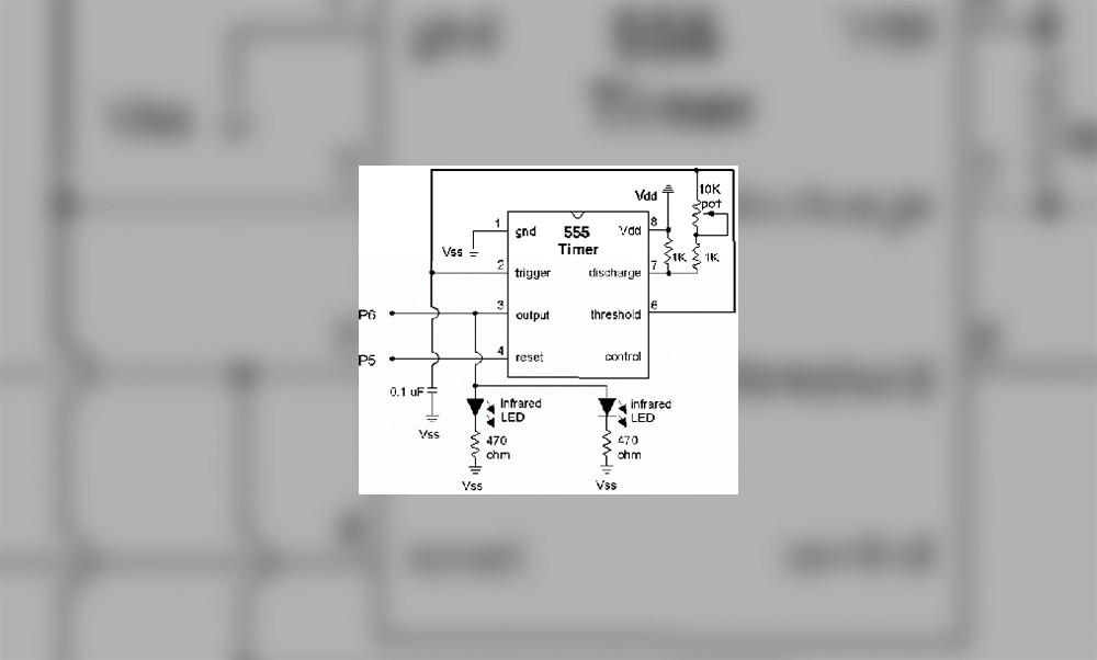
we will us a 555 timer to produce the desired frequency. There are
many other type of frequency generating circuits, but the 555 is the
easiest. This frequency can be tuned using a potentiometer. Below is a
parts list.
1 - breadboard for
prototyping (very highly recommended!)
1 - 555 timer
1 - 1-10k potentiometer (value is not imperative)
1 - 0.01 uF cap
2 - 1k resistors
2 - IR receivers (preferably Panasonic 4602 available a Digi-Key.
If you buy Radio Shack detectors don't expect it to work well at all)
2 - IR LEDs
2 - 470 ohm resistors
2 - 0.1 uF caps
This project involves two
parts, first, we set the 555 circuit to produce the desired frequency,
then, we set up the IR detectors, and LEDs, and write the
code. We will cover part one this month, and part
two next month.
The first step in building this circuit is to place all the
components on your bread board using the schematic below
Note: Unless your
detector requires a modulated frequency, i.e., off, on, off, on, hook the
VDD pin to the reset pin.
Next,
program your controller using the code below. If you are using something
other than a Basic Stamp, you should have some sort of display, or
oscilloscope so you can tune the circuit to the required frequency.
'Frequency count Basic Stamp code
frequency var word
high 5 'turn on oscillator unless vdd
is connected to the reset pin
start:
count 6,100,frequency
'count frequency on pin 6
debug dec5 frequency*10,cr
goto start
Once your processor has been programmed you then should
turn the potentiometer until the debug screen, o-scope, or LCD display shows
38,000 (or the correct frequency for your detectors). Once your
circuit is set to the correct frequency, then we can move on to the next
section of our project...
{mospagebreak}
Adapted from the
Stamps In Class robotics
curriculum.
Lets recap what we've done
so far. First, we created a 555 timer circuit to produce a 38-40khz pulse.
We did this so that the detectors would be able to recognize the infrared
light coming from our robots LEDs and no other type of IR light. After
setting up the circuit we then fine tuned it using a simple Basic Stamp
program. At this point in the process we need to put in the LEDs IR
detectors, and write some code to utilize our infrared proximity detection
circuit. Let's get started.
Infrared Detection
The first step is to assemble
all your components on your circuit board or bread board according to the
schematic below.
anything. You can do this by either using you home video cassette recorder
or using a IR an IR detector card from Radio Shack. Although using the
card is probably easier, it's a bit pricey at $5.00 US. Camcorders are
able to pick up the higher wavelength light than a human eye, so therefore
you can "see" the IR LEDs by looking through your viewfinder. If
you DON'T see any light from the LED's then you need to verify that your
circuit is receiving power, and that the output pin is outputting. Next
you need to wire up your detectors using the schematic below. The physical
setup of the detectors and IRLEDs are at a 45 degree angle. The picture
below gives a good representation, with detectors in yellow and IRLEDs in
red.
detector circuit

Got your detectors set up? Verify the pin
connections and fire up your stamp using the code below.
'Basic Stamp Code
'Basic Proximity Detection Part 2
INPUT 0
INPUT 9
start:
debug In0
debug In9,home
goto start
code running, try and put your hand down in front of you detector and LED.
Depending on what detector you have at which pin, on of the debug number
should change from 1 (high) to 0 (low), and remain that way as long as
your hand is in front of it. Now try the other detector, and then both at
the same time.
Once both of your detector and LED pairs are functioning correctly then
try out the code below.
| x var nib RIRdetect var nib LIRdetect var nib INPUT 0 INPUT 9 start: RIRdetect = 0 LIRdetect = 0 'check 10 times for x = 1 to 10 RIRdetect = LIRdetect = next if (RIRdetect <
if RIRdetect < if LIRdetect < goto start rdetection: debug goto start ldetection: debug goto start center: debug goto start |
Note: I have NOT
tested this code as of yet. It came all FROM MY HEAD. If it doesn't work
correctly check for errors. My IRPD circuit is disassembled at the
moment, and I haven't had time to put it back together.
This
is just some basic code that checks for a greater than 60% hit ratio.
Since an output low (0) signals a hit, we test for a value lower than 4.
You can put any code you want into the r and l detection and center
subroutines. Once you have it working congratulations! You now have a
working, albeit, simple obstacle detector.
Limitations
Unfortunately this is just a "simple" detector, and this
layout and design leaves much to be desired. I'd like to talk a little
bit about improvements, and other choices for better and more robust
detectors. First, one of the most cumbersome aspects of this
design is that it utilizes two detectors. This is an added cost and
creates a cluttered and bulky board. Changing this aspect is pretty much
impossible with this layout, which leads into the next problem, no
individual control of LEDs. In order to have just one detector in a IRPD
design, the user or controller must be able to turn on or off each of
the individual LEDs. If you know what LED is on when you detect
something, you can know which direction the hit comes from, with only
one detector. Third, by incorporating a potentiometer into the design
the circuit can be easily de-tuned by a bump or such. Although I'm not
sure, I think that a 160 ohm resistor in place of the pot will generated
a 38kHz pulse. Forth, just two LEDs just won't cut it for total obstacle
detection. Chair legs and such fit nice in-between the LEDs and
detectors without the least bit of trouble. A design which incorporated
a center detector would go a long ways in improving this design. Also,
one or two rear detectors would prevent your robot from backing up into
something.
Thanks for helping to keep our community civil!
This post is an advertisement, or vandalism. It is not useful or relevant to the current topic.
You flagged this as spam. Undo flag.Flag Post
Your post is currently under review by our moderation team. The review process usually takes up to 48 business hours.
You can track your post's status in the "My Content" section of your profile. Once approved, it will be published and visible to others.

Thank you for contributing to our community!