

Building A Maze Solving Robot - My Experiences - Part 2

Unfortunately I didn't get to much done in the way of coding. I was, however, able to get quite a few hardware advancements in place this month. These include:
Ok, last time we talked about my brand new (supposedly) maze solving
robot. I have to admit that it is hard to keep on track with just
making it a maze solver. There is so much more that I want to add! Oh
well, so little time.
Unfortunately I didn't get to much done in the way of coding. I was,
however, able to get quite a few hardware advancements in place this
month. These include:
1. Servo encoders
2. Omnidirectional caster wheel
3. Bumper switches
4. Mounted OOPic board above chassis.
Servo Encoders:
To find out more about this encoder, and how to add one to your robot click here.
It has long been my dream to be able to encode my robot's wheel
revolutions. Shortly after beginning this project it became evident
that encoders would be a must. I then embarked on a very long and
not-so-fun trip to find an easy and inexpensive way of adding them. I
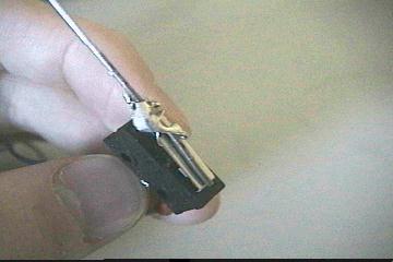
finally found it! The principal involves a photointerrupter creating a
pulse stream as holes in the main drive shaft pass by. Although this
arrangement only creates 6 pulses per wheel revolution it is acceptable
for my application. I brought the pins of the phototransistor and the
photodiode outside of the servo case, so that I could hook up wires to
them.
Now
I only have to connect up power (with current limiting resistor) to the
photodiode and use a voltage divider arrangement to read the pulse
stream into my OOPic. The code below will read in the pulse stream and
blink an LED every time a pulse is encountered.
oDIO1 encoder = New oDIO1;
oDIO1 led = New oDIO1;
oCounter counter = New oCounter;
oByte Lcount = New oByte;
sub void main(void) {
Setup;
encoder.direction = cvInput;
encoder.IOLine = 30;
led.IoLine = 31;
led.Direction = cvOutput;
Do {
if (Lcount > 6) {
led = 1;
Lcount = 0;
}
led = 0;
} While (1);
}
sub void Setup(void) {
counter.ClockIn1.link (encoder.value);
counter.Output.link (Lcount.value);
counter.Direction = cvPositive;
counter.Operate = cvTrue;
counter.Mode = cvCount;
counter.Tick = 0;
encoder.direction = cvInput;
encoder.IOLine = 30;
led.IoLine = 31;
led.Direction = cvOutput;
}
Sometime in the near future I hope to be able to get the other wheel outfitted with an encoder.
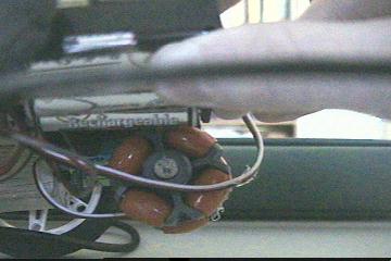
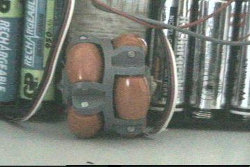
Omnidirection Castor Wheel:
Ok, I'm sure your asking the question, "what in the world is
an omnidirectional castor wheel?" Well, simply put, it is Ezekiels
"wheel within a wheel." Basically it is a wheel with smaller rollers
around the outside of it. In this case they saying "a picture is worth
a thousand words" is definitely the case!
The cute little wheel usually run at a whopping $13. But, I was able to
pick one up for $6.12. A local robot geek had bought $100 worth of them
to get the discount. If you up to paying full price you can click on
over to Acroname a pick one up.
The wheels actually work quite nicely. I've heard of people mounting
three around their 'bot, so it could move any direction without
turning! Since they are plastic there is not a huge amount of grip on
them. One thing you must pay close attention to when mounting them is
how level they are. You must make sure they are completely level so
they don't wobble. When on of the red rollers is in contact with a
surface the other side of the wheel should not be touching. This allows
it to move freely from side to side.
I mounted mine my taking a small dowel rod and drilling a hole through
its center. I then hot-glued a piece of music wire through the center
and brought the ends of the wire up to the bottom of the bot and
fastened it with hot-glue. Unfortunately when I glued the wheel at its
final height the 'bot was not completely level. Now he leans ever so
slightly forward. Normally this wouldn't be a problem, but it turns out
that my IRPD array is quite sensitive and picks up the floor quite a
bit.
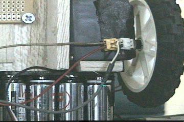
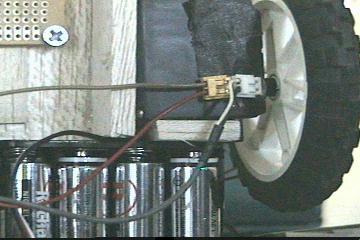
Bumper Switches:
After a few short minutes of running my 'bot I quickly
realized that front and back bumpers were a must! IRPD may be good, but
it ain't good enough! Thankfully I had a couple of Rat. Shack switches
in my junk box. I spent a long time trying to get the whisker attached
to the tongue of the switch. I was finally able to get the solder to
partially stick. I used a lot of small wire and solder to get it to
stay.
I wired up the switch to my OOPic, connecting the switch from 5v
through a resistor into a pin, but I was unable to get it to register
the switch. It then occurred to me that I needed to bring a wire to
ground. This makes the switch behave correctly. Now the connection is
Vcc through switch, and one wire goes to the I/O pin, and one goes
through a resistor to ground.
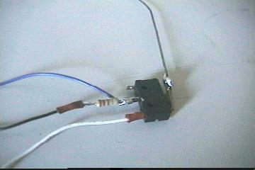
White is 5v, black is ground, and blue is the I/O line.
I mounted one on the front of the 'bot, and how to add one at the back
soon.
Below is the event driven code for detecting when the switch closes. It
simply turns on a LED, and turns it off when the switch closes.
oDIO1 front_bumper = New oDIO1;
oEvent bump = New oEvent;
oGate bump_gate = New oGate;
oDIO1 led = New oDIO1;
sub void main(void) {
Do {
led = 1;
} While (1);
}
sub void bump_code (void) {
led = 0;
}
sub void Setup(void) {
led.IoLine = 31;
led.Direction = cvOutput;
front_bumper.IoLine = 26;
front_bumper.direction = cvInput;
//You can't directly link a I/O line to the oEvent object. You must
//connect through a oGate or similar object
bump_gate.Input1.link(front_bumper);
bump_gate.Output.link(bump.Operate);
bump_gate.Operate = cvTrue;
}
Mounted OOPic Board Above Chassis:
Now this hardware modification was purely aesthetic. I bought some
of the Radio Shack PC board stand offs so that I could raise the OOPic
off the surface of the chassis.
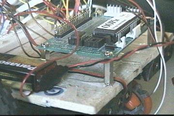
Unfortunately, the battery packs were mounted directly underneath the
board, so I was unable to screw the bottom of the standoffs onto the
chassis. I had to resort to more modern means - hot-glue. Hot-glue
works wonders, and it is now holding my OOPic board onto my chassis. If
I ever decided to convert this little 'bot to a fire-fighter I will
definitely need more room. If that happens I plan on using some larger
standoff and mounting a second 6x6in platform above to base.
Maybe next month I will have some working code! It getting pretty close to the deadline. I guess I should speed things up!
Continue Reading ...
Thanks for helping to keep our community civil!
This post is an advertisement, or vandalism. It is not useful or relevant to the current topic.
You flagged this as spam. Undo flag.Flag Post
Your post is currently under review by our moderation team. The review process usually takes up to 48 business hours.
You can track your post's status in the "My Content" section of your profile. Once approved, it will be published and visible to others.

Thank you for contributing to our community!