 Barobo Linkbot
's Linkbot all-in-one smart actuators allow anyone without any knowledge of robotics to create and "program" robots. Each actuator is packed with many features including:
•
Atmel AVR Microcontroller: Compatible with
Arduino so you can re-flash with your own firmware using the on-board bootloader
•
ZigBee-Capable Radio: Communicate wirelessly with an 802.15.4-compliant radio, create mesh networks, control and monitor remotely
•
Multi-Color (RGB) LED: Select from a full spectrum of colors
•
Buzzer: Play notes or complete tunes, give audio responses to inputs
•
3x Buttons: Easily control Linkbot modes and functions or write custom functions for button presses
•
Micro-USB Connector: Connect to a computer or charger with a standard Micro-USB cable
•
Rechargeable Lithium-Ion Battery: Run your Linkbot for over 3 hours for most applications before having to charge
•
Polycarbonate Housing: Super-durable, drop-tested from second-story building (not recommended) so it can handle your demanding projects
•
SnapConnector Mounting Surfaces: Quickly connect and remove wheels, connecting plates, grabbers, even multiple Linkbots; or connect your own accessories with standard screws
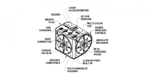 Linkbot Features
With so many features, it's hard to categorize it simply as a "smart actuator". The actuator comes in two different versions: the LinkBot-L which has two rotating surfaces set 90 degrees apart, and the LinkBo-I which has two independent rotating surfaces parallel to one another.
 Linkbot-L Modular Robot Actuator showing two rotating surfaces.
 Linkbot-I Modular Robot Actuator showing one fixed and one rotating surface.
Each of the rotating surfaces can be easily distinguished because of the black color, while the third fixed surface is white. With the right bracket, a simple LinkBot-L can be used as a pan and tilt system. Connect an idler wheel to the Linkbot-I and you have a 2WD rover. Connect a few of them together and you have a versatile multi degree of freedom robotic arm. We were very curious to see what was under the hood and with Barobo's support, disassembled a LinkBot-L.
The Barobo actuator disassembles into two main parts: the outer shell and an inner electronics / actuators module. The actuator disassembled here shows the L shaped actuator where there is one motor on the bottom, and another at 90 degrees. We strongly suggest not disassembling your own actuator as the external case is held together largely using strong adhesive; bending or flexing the parts too much may cause them to crack or break.
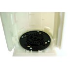 Linkbot Side 1 Back Linkbot Side 1 Back |
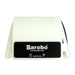 Linkbot Rear Linkbot Rear |
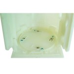 Linkbot Side 3 Back Linkbot Side 3 Back |
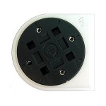 Linkbot Side 1 Linkbot Side 1 |
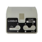 Linkbot Interface Linkbot Interface |
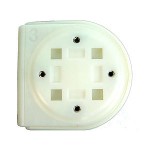 Linkbot Side 3 Linkbot Side 3 |
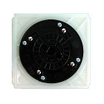 Linkbot Side 2 Back Linkbot Side 2 Back |
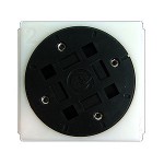 Linkbot Side 2 Linkbot Side 2 |
|
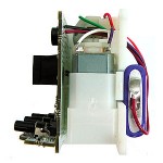
Once side #2 has been removed, the inner electronics essentially drop out. This inner part contains the "core" of the Linkbot, including the two DC gear motors, the PCB (microcontroller with motor controllers, sensors, etc), LiPo battery and wiring.
|
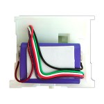 LinkBot Battery LinkBot Battery |
|
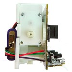 Linkbot Motor 2 Linkbot Motor 2 |
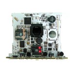 Linkbot PCB Linkbot PCB |
 Linkbot Motor 1 Linkbot Motor 1 |
|
 Linkbot Button Module Linkbot Button Module |
|
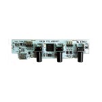
With the shell removed, we can take a better look at the electronics and how the Linkbot operates. There is one main PCB as well as a "daughter board". The daughter board extends the PCB at 90 degrees to make the three buttons accessible and incorporates the USB connector.
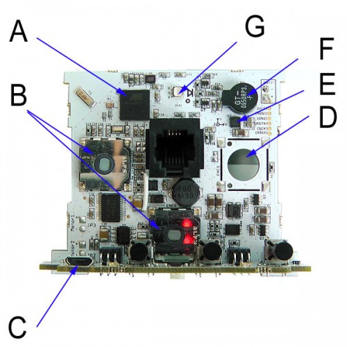 Linkbot PCB Features
A: ATMEL MEGA 128RFA1 microcontroller
B: Encoders (provide angular feedback)
C: USB port (for uploading new code)
D: Empty encoder slot (for -I type)
E: Accelerometer (can detect acceleration and gravity)
F: Buzzer (auditory feedback)
G: RGB LED (visual feedback)
One feature which seems to be missing is an On/Off switch, which means the actuator is always ON and should ideally be charged before each use. However, if you leave it on a shelf with none of the actuators moving, the LiPo battery should last for quite a while.
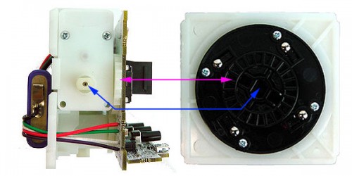 Linkbot Actuator Feedback
The Linkbot uses a pair of DC gear motors which on their own do not have any feedback. However as you can see in the image above, the DC motor rotates the black plastic disc (marked in blue) which has an integrated ring of gears. These gears mesh with a spur gear (marked in purple) which is connected to an encoder on the PCB. This approach is used for each motor. Therefore when you press the "record" button and move the actuators, the processor is reading the changes in the encoder values. When you press playback, it rotates the motor(s) in the right directions while reading and comparing encoder values.
We look forward to seeing what you do with your LinkbBts!

 Linkbot-L Modular Robot Actuator showing two rotating surfaces.
 Linkbot-I Modular Robot Actuator showing one fixed and one rotating surface.


