

Drive Motor Sizing Tutorial

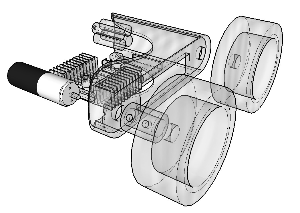
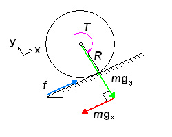
This tutorial is intended to complement RobotShop's Drive Motor Sizing Tool by providing you with a step by step explanation as to the calculations behind the dynamic tool. In the image below, half a mobile robot is shown. Although in this scenario only two out of the four wheels are driven, the equations below can be used for any number of passive and driven wheels, as well as for tank tracks. The equations are presented without units (units are presented with the drive motor selection tool).
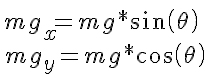
To calculate the required torque, power, current and battery pack required by a wheeled mobile robot, there are several principles that must be understood: concept of vectors; 2D Force balance; Power; Current and Voltage. If you do not understand these concepts, you are encouraged to research them prior to reading this tutorial. In order to roll on a horizontal surface, a wheeled robot’s motors must produce enough torque to overcome any imperfections in the surface or wheels, as well as friction in the motor itself. Therefore theoretically, a robot (small or large) does not require much torque to move purely horizontally. Obviously there will be more friction and resistance in a large robot than in a small robot, though it is still exponentially less than when a robot encounters an incline. In order for a robot to roll up an incline at a constant velocity (no acceleration or deceleration) it must produce enough torque to “counteract” the effect of gravity, which would otherwise cause it to roll down the incline. On an inclined surface (at an angle theta) however, only one component of its weight (mgx parallel to the surface) causes the robot to move downwards. The other component, mgy is balanced by the normal force the surface exerts on the wheels.
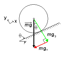
In order for the robot not to slide down the incline, there must be friction between the wheel and the surface. The motor in a heavy truck may be able to produce 250 horsepower and significant torque, but we have all seen (in person or in video) large trucks simply spinning their wheels as they fall backwards on an icy street. It is friction (f) that “produces” the torque.
The torque (T) required is:
![]()
To select the proper motor, we must consider the “worst case scenario”, where the robot is not only on an incline, but accelerating up it.
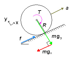
Note now that all forces (F) are along the x and y axes. We balance the forces in the x-direction:

Inserting the equation for torque above, and the equation for mgx, we obtain:

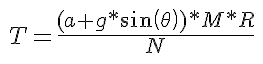
Rearrange the equation to isolate T:

This torque value represents the total torque required to accelerate the robot up an incline. However, this value must be divided by the total number (N) of drive wheels to obtain the torque needed for each drive motor. Note that we do not consider the total number of passive wheels as they have no effect on the torque required to move the object aside from adding weight.
The final point to consider is the efficiency (e) in the motor, gearing and wheel (slip).
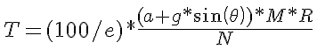
The value for efficiency here represents the total efficiency of the system and can be estimated as follows:
- Battery -> Motor Controller: 95% efficient
- Motor Controller -> Motors: 96% efficient
- Brushed DC motor: 92% efficient
- Spur gear (each stage): 93% each stage (estimate 5 stages?)
Each step reduces the total efficiency by their respective percentage, so the total efficiency in this example would be:
95% x 96% x 92% x 93% x 93% x 93% x 93% x 93% = 58%
0.95 x 0.96 x 0.92 x 0.93^5 = 0.58
In most cases you will find that using inexpensive parts decreases the efficiency of the system and even 58% total efficiency is rather high. The lost energy is transferred mostly to heat and noise.
Taking into consideration the efficiency of the system increases the torque required to compensates for inefficiencies. Total power (P) per motor can be calculated using the following relation:
![]()
T is known from above and the angular velocity (w) is specified by the builder. It is best to select the maximum angular velocity to be able to find the corresponding maximum power. Knowing the maximum power and the supply voltage (V) which the builder chooses, we can find an idea of the maximum current (I) requirements:
![]()
The two equations above are used to produce the following relation:
![]()
Finally, the capacity (c) of battery pack required can be estimated using the equation:
![]()
You may wonder why such a large value is needed. This is because when choosing a battery pack, the rated amp hours are not an accurate indicate of the maximum current the pack can produce for extended periods of time. Also, the total charge is rarely retained over time. This way you will ensure the battery pack you select will be capable of producing the current your motors require, for the time you require and with the inefficiencies inherent in recharging battery packs. Note: This is the battery required PER MOTOR. To obtain a total battery pack required for the robot, multiply this value by the number of drive motors.
Thanks for helping to keep our community civil!
This post is an advertisement, or vandalism. It is not useful or relevant to the current topic.
You flagged this as spam. Undo flag.Flag Post
Your post is currently under review by our moderation team. The review process usually takes up to 48 business hours.
You can track your post's status in the "My Content" section of your profile. Once approved, it will be published and visible to others.

Thank you for contributing to our community!