

Arduino-Powered Desktop Pal – Lesson 4: Adding “Stereo” Ultrasonic Vision and Passive Infrared Sensing

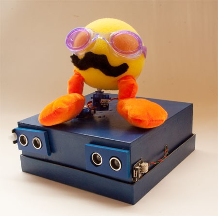
 Desktop Pal with "stereo" ultrasonic sensors and PIR detector
Getting the File Downloads
All of the example sketches are contained in a single zip file above. Download this file and extract the individual folders in it to your Arduino sketchbook.Important! You must also download and install several Arduino libraries, required by the sketches in this installment. These libraries are provided in Lesson 3, so if you’ve been following along in this series, you should already have them. This lesson does not require any additional libraries other than those provided for in Lesson 3.
Remember: When adding new libraries, you must exit the Arduino IDE if it is open. Once you have copied he library files to the Arduino sketchbook libraries folder, you may restart the Arduino IDE.
Adding More Parts to the Desktop Pal
We need a few more parts added to Desktop Pal in order to endow it with additional functionality. In this lesson you’ll add the following additional components:- Second HC-SR04 Ultrasonic Range Finder: Your Desktop Pal already has one of these ultrasonic sensors attached to it. In this installment you’ll add a second sensor to the other side of the Desktop Pal enclosure. To connect this sensor to your microcontroller, you will use another four of the jumper wires from the Jumper Wires Premium 6" F/F Pack of 20, which you should have left over from Lesson 1.
- Passive infrared (PIR) detector module: This module detects motion of objects. The output of this module is like a switch: when there’s motion, the switch is turned on. Desktop Pal uses this switch as a “doze” control – if no motion has been detected for the last minute, the Pal goes into a light sleep. This module comes with its own connection cable.
- Electronic Brick Buzzer: Since the Desktop Pal tucks its Arduino-compatible microcontroller inside an enclosure, there’s no way to use the various LEDs on the controller board to monitor status. The buzzer provides an audible version of the LED that’s hard-wired to pin 13 of the Arduino.
- Servo Extension Cable 150mm: Use this cable to connect the brick buzzer to the Itead Leonardo board.
Adding the Second Ultrasonic Sensor
If one ultrasonic sensor allows the Desktop Pal to detect objects around it, imagine what two ultrasonic sensors can do! By adding a second sensor, you can give the Pal a form of stereoscopic vision. Differences in the range values provided by the two sensors let the Pal determine if an object is to its left, right, or center.Tip: In my prototype Desktop Pal, I used an enclosure box measuring 8” by 8”. This provides a five inch separation of the two ultrasonic sensors (measured at their centers). That’s enough for a good stereoscopic spread. If your enclosure is smaller, you may want to think about moving it into a larger one, or else putting the two ultrasonic sensors on “side booms” to help spread them out.
- Make two large holes for the ultrasonic sensor in the upper left front of the enclosure. Use your ultrasonic sensor as a template for the hole spacing and size. For the prototype, I created the holes by pushing a hobby knife through the paper mache box, and then enlarged the hole by rotating the blade.
 Wiring diagram for the left ultrasonic sensor
- Use four of the 6” female-to-female jumper wires from your set of the Jumper Wires Premium 6" F/F Pack of 20, referenced in Lesson 1,. to connect the second ultrasound sensor to the Itead Leonardo, as indicated in the wiring diagram. Be sure to use the 3-pin headers for Pin 10 and Pin 11.
Warning: Be absolutely certain not to cross the connections to the sensor. Be especially sure you don’t mix the G and V pins on the 3-pin header, or else you could damage the sensor, and possibly your Itead Leonardo board! The G (for ground) and V (for V+) are the power connections, and mixing them up can lead to bad things.
- Position the ultrasonic sensor inside the enclosure so that its transceivers poke through the holes you previously cut. The 4-pin connector of the sensor should point toward you, to provide easy access to the wiring.
- Apply a very small dab of hot melt glue to one or both sides of the sensor, to keep in place.
- You may wish to cover up the mounting holes for the ultrasonic sensor using a plastic bezel, colored tape, or other decoration.
Adding the PIR Sensor
If you have an automatic light on your driveway or front porch, it most likely uses a passive infrared (PIR) sensor to detect motion. These sensors are now ubiquitous in both indoor and outdoor security. The Desktop Pal uses the same kind of sensor to detect when there’s motion around it, such as a human or animal passing by. The output of the sensor is just like a switch connected to the Arduino:- When there’s no motion detected, the value of the sensor is 0 (off)
- When motion is detected, the value of the sensor toggles to 1 (on)
Tip: The PIR sensor I’ve selected for the Desktop Pal project has its own blue LED, which glows whenever the sensor is activated (ON). You can use this LED to verify operation of the sensor.
PIR sensors are said to detect the heat given off by humans and other warm-bodied critters. That’s somewhat true, but not entirely accurate; understanding how they work can aid in predicting when and why the sensor may be activated. Inside the PIR module is a set of two infrared-sensitive detectors. These detectors are made to respond to infrared radiation emitted by or reflected from objects, living or not. While certain kinds of infrared light may be associated with “heat” (the sun, an infrared heat lamp), PIR sensors don’t actually measure this heat. They are sensitive to radiation in the infrared end of the electromagnetic spectrum. By comparing changes between the two sensors, the module can determine likely motion. If you stand perfectly still in front a PIR sensor, it will no longer “see” you no matter how hot you are, because you’ve not moving. Once you flex a muscle, that new movement is detected, and you’ve been found. Aiding the detection range is a (usually) white plastic lens that collects the infrared radiation from the desired field of view. Most PIR sensors are designed to have a detection “cone” of 70 to 120 degrees, sometimes even more. (The sensor selected for Desktop Pal has a sensing angle of 100 degrees.) While PIR sensors are very good at ignoring common light sources, they can be triggered by sudden glints of sunlight or incandescent light, curtains fluttering in the wind, even air currents from a heat register in the wall, floor, or ceiling. For best results, aim your Desktop Pal so its PIR sensor is away from anything that might wrongly influence its motion detection. Passive infrared detector module attached to side of the Desktop Pal
- Use hot melt glue to mount the sensor on the left side of the enclosure. The lens of the module should protrude beyond the front of the enclosure.
 detector module") Wiring diagram for the passive infrared (PIR) detector module
Wiring diagram for the passive infrared (PIR) detector module- Using the 3-wire cable that comes with the PIR module, connect the sensor to the Itead Leonardo board as shown. It must be connected to the 3-pin header for Pin 3. Be sure to orient the black wire to the ground (G) pin.
- Snap the other end of the included 3-wire cable to the sensor board. This connection is polarized, and can be plugged in only one way.
Mount and Wire the Electronic Brick Buzzer
It’s always handy to know what your Arduino is up to. Ordinarily, you can glance at its various LEDs to verify that it’s on and working. The LED connected to Pin 13 can serve as a status indicator, both during sketch uploading, and when running a sketch. While mounting some status LEDs to the outside of the Pal enclosure is an option, there’s another method that combines the verification of an LED, with audible feedback of a piezo sound element. The Electronic Brick Buzzer is a self-contained sound module that serves the same function of a status LED, but with the benefit of being able to hear it, even when it’s mounted inside the enclosure.- The module emits a tone when the pin it’s connected to is toggled LOW (0)
- The module is quiet when the pin is toggled HIGH (1)
Tip: Because the buzzer is “active LOW,” it will produce sound when the Pin 13 LED is off. This is the usual state of the LED when not programmed otherwise, and when no sketch is being uploaded. Because of this, the buzzer will always sound unless you add code to turn it off. More about this in a moment.
Note that some documentation for the Electronic Brick Buzzer reverses the function of the LOW and HIGH signals. In this module, the sound is indeed emitted when the pin goes LOW.
 Wiring diagram for the electronic brick buzzer module
- Use the 150mm servo extension cable to connect the electronic brick buzzer to the 3-pin header for Pin 13. Be sure to orient the black wire to the Ground (G) connection on the header, and to the ground (G or –) pin on the buzzer module.
 Electronic Brick Buzzer taped to the inside front of the Desktop Pal enclosure
- Use double-sided foam tape or hot melt glue to affix the module to the inside front of the Desktop Pal enclosure.
Tip: Be sure to keep ready access to the servo extension on Pin 13 of the Itead Leonardo, so you can disconnect the buzzer when you need to, like when developing sketches.
Testing the Electronic Brick Buzzer
As a first order of business, let’s test the operation of the buzzer, since it will sound unless we specifically write code to shut it up. So for this and all future sketches, specific code is added to control pin 13.- Be sure to first download all of the example sketches for this lesson to your Arduino sketchbook, and unpack them.
- Open the PalBuzzer.ino sketch in the Arduino IDE, compile it, and upload it to the Itead Leonardo.
Note: The code below is not commented in the interest of brevity. The actual .ino sketch file contains embedded comments for you to review.
void setup() {
pinMode (13, OUTPUT);
digitalWrite(13, HIGH);
}

void loop() {
digitalWrite(13, LOW);
delay(200);
digitalWrite(13, HIGH);
delay(2000);
}
The sketch begins by using the setup() function to make pin 13 an OUTPUT, and setting its value to HIGH. This stops the buzzer from making any output.
In the loop() function, pin 13 is toggled between LOW and HIGH. Tone is emitted for 200 milliseconds, followed by 2 seconds of silence.
Once tested, if you’d like to unset the tones, comment out the four lines in the loop() function, and re-upload the sketch. The buzzer will now only sound during sketch uploading, and once or twice briefly when the Itead Leonardo first powers up.
Tip: In addition to simple on/off tone, the buzzer can recreate simple musical notes by using pulse width modulation (PWM). I’ll cover this feature in an upcoming lesson.
Testing the Second Ultrasonic Sensor
Now to test the second HC-SR04 ultrasonic sensor that you added. For this test, I am assuming you’ve already read through Lesson 2 of this series, where you testing your Desktop Pal’s first ultrasonic sensor. In Lesson 2 you downloaded and installed the helper library for the HC-SR04 ultrasonic sensor. This is an important step, or neither of the ultrasonic sensors will function.- Open the PalUltrasonicTest2.ino sketch in the Arduino IDE.
- Compile the sketch and upload it to the Itead Leonardo.
- Open the Serial Monitor window by clicking the Serial Monitor icon (far right) in the Arduino IDE toolbar.
Tip: If all you see is a series of “0 cm” readings, or other readings that don’t change regardless of the distance between the sensor and your hand, the sensor may not be connected properly. Recheck your wiring.
This sketch is a modified version of the PalUltrasonicTest sketch you tried in Lesson 2, so I won’t go into additional detail here, except to note the lineUltrasonic ultrasonic(10,11);which sets up the sensor to use pins 10 and 11 for the trigger and echo connections to this sensor. For the right sensor, the sketch used pins 5 and 6.
Test Both Ultrasonic Sensors Together
With the operation of the left ultrasonic sensor verified, let’s develop a method for reading both of them, and keeping separate track of the distance values they produce.- Open the PalUltrasonicTestStereo.ino sketch in the Arduino IDE.
- Compile the sketch and upload it to the Itead Leonardo.
- Once the sketch is uploaded, open the Serial Monitor window. You should see a set of two numbers, separated by a comma. The first number is the distance, in centimeters, from the left sensor; the second number is the distance from the right sensor.
Ultrasonic ultrasonicR(5,6);
Ultrasonic ultrasonicL(10,11);
The sketch begins by creating two objects, one for each ultrasonic sensor. For ease of use, I’ve named the right sensor ultrasonicR, and the left sensor ultrasonicL. Clever, no?!
void loop() {
  int sonicValR = getUltrasonic(ultrasonicR);
  delay (40);
  int sonicValL = getUltrasonic(ultrasonicL);
  Serial.print(sonicValL);
  Serial.print(",");
  Serial.println(sonicValR);
  delay(1000);
}
The loop function repeatedly grabs values from both sensors, and then prints them in the Serial Monitor window. Take note of a few things in this code:
- The left and right sensors are fetched separately, and their values stored in a pair of variables for easy comparison. (This code will be further developed in the next lesson.)
- The 40 millisecond delay between reading the right and left sensors guarantees the maximum delay to allow for an echo. This makes sure the second sensor is not read before the first sensor has had its chance to return a valid signal.
- The loop is repeated once a second, using delay(1000).
int getUltrasonic(Ultrasonic sensor) {
  int total = 0;
  int sonicVal = 0;
  int counter = 0;
  while (counter < 3) {
    delay (38);
    sonicVal = sensor.Ranging(CM);
    if (sonicVal < 500) {
      total = total + sonicVal;
      counter++;
    }
  }
  return (total / 3);
}
The sketch packages the actual reading of the ultrasonic sensors in a user-defined function, getUltrasonic. The function first “passes in” a reference to the sensor object to use, either the right sensor, or the left sensor. By passing this value to the function, the one function can be used with any number of ultrasonic sensors connected to the Arduino.
This reference is in the form of:
( DataType parameter )where DataType defines the type of data being passed into the function, and parameter is a variable that’s used in the function to represents the ultrasonic sensor to read. The specific sensor to read is defined when the function is called from within the loop(). Example:
getUltrasonic(ultrasonicR)This line passes the ultrasonicR object to the getUltrasonic function – this is the sensor that’s read that time around. Then,
getUltrasonic(ultrasonicL)passes the ultrasonicL object to the function, and it’s the left sensor that gets now read. The main guts of the getUltrasonic function is a while loop that collects a total of three separate readings from the sensor. If the reading is less than 500, it’s used to calculate an average of three separate reads. The averaging – and tossing out any value over 500 – is meant to ignore any possible noise or glitches in the values retrieved from the sensor.
Testing the PIR Sensor
The passive infrared sensor is used to note when there’s movement in front of the Desktop Pal. If there’s no movement, maybe no one is in the room, so the Pal can take a quick catnap. If the sensor is subsequently triggered, it means there may be someone in the room to entertain, so the Pal wakes up.Important: For this test, I am assuming you’ve already read through Lesson 3 of this series, where you installed the Metro timer library described in that installment. This sketch will not work if the Metro library is missing.
- Open the PalPIRDoze.ino sketch in the Arduino IDE.
- Compile the sketch and upload it to the Itead Leonardo.
- Once the sketch is uploaded, open the Serial Monitor window. You should see a set of two numbers, separated by a colon (see the Figure). The first number is a timer counter, running from 1 to 11.
- 0 means false; Pal is awake and raring’ to go
- 1 means true; Pal has dozed off because there’s been no movement detected during a specific period of time
#include <Metro.h>
Metro dozeMetro = Metro(1000);
These lines add a reference to the Metro timer library, and create a new object (named dozeMetro) which has a one second interval. This interval causes the dozeMetro object to elapse once every second; it provides a nice way to keep track of time events without a lot of extra coding on our part. Recall from Lesson 2 that the Desktop Pal’s side switch is used with an Arduino interrupt, to make sure that any triggers of the switch are not missed because the code is busy doing something else. The same concept is used with the PIR sensor:
volatile int dozer = 0;
volatile boolean doze = false;
attachInterrupt(digitalPinToInterrupt(3), triggerPIR, RISING);The first two lines create global variables that are used later in an Arduino interrupt service routine (otherwise known as an ISR). The ISR is just a user-defined function that is registered ahead of time with the Arduino, so the board knows what to do when the interrupt occurs. In this code, when an interrupt occurs on pin 3, the processor must put everything else on hold, and immediately branch off to a function named triggerPIR. The RISING in the line of code specifies the pin change that causes the interrupt to occur. Valid choices here are HIGH and LOW, for when the pin goes to either HIGH or LOW, CHANGING for when there is any change in the pin, and RISING or FALLING, which trigger on the LOW/HIGH or HIGH/LOW transition, respectively.
Tip: The volatile keyword used when defining the dozer and doze variables forewarn the Arduino compiler that these values may be subject to change from outside the main execution of the processor (in this case, the ISR).
Using volatile instructs the compiler that these variables must always use the Arduino’s RAM memory, rather than one of its hardware registers (a kind of temporary holding tank). The values of the variables are thus guaranteed to be accurate at any time, regardless of how they are changed in the sketch.
The interrupt service routine for the PIR sensor is simple:void triggerPIR() {
dozer = 0;
doze = false;
}
When the interrupt occurs, the code resets both the dozer timer counter, and the doze flag variable.
Finally, inside the loop() function is a while loop that repeats as long as the doze flag is set to false, and only when the dozeMetro interval has transpired:
while (!doze && dozeMetro.check() == 1) {
  if (dozer++ >= 10) {
    doze = true;
  }
  if (digitalRead(3) == 1) {
    dozer = 0;
    doze = false;
  }
  Serial.print (dozer);
  Serial.print (":");
  Serial.println (doze);
  delay(5);
}
The code
dozeMetro.check() == 1executes the innards of the while loop only once every second, but without having to use a delay statement (the delay statement that’s there is just for testing purposes). When not dozing, the dozer counter is incremented by 1s, once a second. If dozer reaches 10, Pal dozes off until the PIR sensor turns it back off again. The line:
if (digitalRead(3) == 1)resets the dozer and doze variables as long as the PIR sensor continues to register motion.
Coming Up…
We covered quite a bit here. In the next lesson, you’ll discover how to fuse all of Desktop Pal’s sensors and sound output to make a truly reactive creature. Thanks to its twin ultrasonic rangefinder sensors and “stereo vision,” the Pal can be programmed to interact with objects nearby, seemingly following movement passing in front of it, and more.Thanks for helping to keep our community civil!
This post is an advertisement, or vandalism. It is not useful or relevant to the current topic.
You flagged this as spam. Undo flag.Flag Post
Your post is currently under review by our moderation team. The review process usually takes up to 48 business hours.
You can track your post's status in the "My Content" section of your profile. Once approved, it will be published and visible to others.

Thank you for contributing to our community!