

Arduino-Powered Deskbot Pal - Lesson 1: Assembly


It’s an easy-to-build and affordable animatronic emoji that sits on your desk!
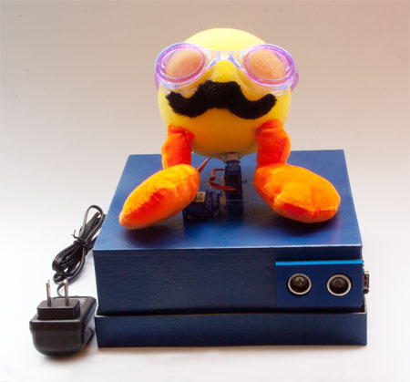 Finished Desktop Pal
What is Desktop Pal?
At its core, Desktop Pal is a box with a pair of small servos glued to the top. The servos are oriented in a simple pan and tilt mechanism, which rotates a foam ball “head.” The brains-in-the-box is an Arduino microcontroller; connected to it are a bevy of sensors and other accessories to make a fully reactive robot. Desktop Pal is different from many other robot building projects in that it requires no special construction tools, and absolutely no soldering! Sure, you can solder up stuff if you like, but the project is designed so you don’t have to touch a soldering iron. This makes it the perfect project for younger builders, or for those in school settings where soldering irons are often not allowed.What You’ll Learn
In this new series of blogs, I’ll show you how to build your own Desktop Pal. In this installment, you’ll learn what materials you need, and how to assemble your robot using just a hot melt glue gun and a hobby knife. In future articles, I’ll show you how to connect various sensors to make your Pal react to its environment. Your Pal will notice when someone has entered the room, stands in front of it, waves her hand, or even speaks! And in return, Desktop Pal will buzz, beep, make cheerful chirpy sounds, flash lights, and play your favorite music. So let’s get started!Rounding Up The Basic Parts
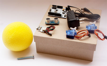 Main components of Desktop Pal
Tip: You can get all the electronic parts right here on RobotShop. Visit your neighborhood craft or hobby store for the enclosure box, foam ball, and decorations.
- Itead Leonardo Microcontroller, a 100% compatible Arduino board that has servo/sensor connections already on it. This terrific board makes it super easy to attach servos and sensors to your Arduino, without having to use a separate motor shield.
- Two 9 gram micro servos. I’m using the RB-Fit-03 motors, which I like because their wires are long enough to not require the use of separate servo extensions.
- Two HC-SR04 Ultrasonic Range Finder modules. These sensors allow the Desktop Pal to see objects in front of it. (The project uses two sensors, though only one is installed for now. You’ll add the second one later.)
- A Crash Sensor (Left), which is a spring-loaded leaf switch used for basic interaction with the Desktop Pal. For example, pressing the switch while your Pal is awake will put it to sleep, so it stops yakking at you. Press it again, and it wakes up.
- 7.5VDC 1 amp Wall Adapter Power Supply. Because the Desktop Pal is a stationary robot, you can use a convenient power adapter to provide its juice, rather than a set of batteries.
- A set of Jumper Wires Premium 6" F/F Pack of 20. These are jumper wires with female-to-female connectors already crimped on them. For this project you’ll only use four, so you’ll have some extra for next time..
- Enclosure box. My prototype used a 7” x 7” x 4” paper mache box, purchased at a local Michael’s craft store. If you can’t find exactly this type, just about any other similarly sized box will do
- 4” low density (soft) foam ball. The ball acts as your Pal’s head. It needs to be low mass to keep the weight to a minimum. Stuff needs to be pinned to it, so don’t go with a ball that you blow up with air. If you can’t find one exactly like the kind I used, you can use instead one of those white Styrofoam balls for flower and craft decorations.
- A 2” long by 1/4”-20 hex head bolt (get this at your local hardware store). The bolt serves as a stem for connecting your Pal’s head to its servo body.
- Various decorating stuff for personalizing your Pal. I found mine at the local dollar store, plus a couple side-trips to nearby resale outlets.
- Hot melt glue gun, either low or high temperature.
- Small (#00) Phillips screwdriver.
- Some 1” x 1” squares of double-sided foam tape.
- Hobby knife (careful: it’s sharp).
- Ruler, for measuring.
Preparing the Enclosure Box
The main electronics for the Deskbot Pal, including the Itead Leonardo board, go inside the enclosure. This means we need to poke some holes into the box for the wires and various sensors.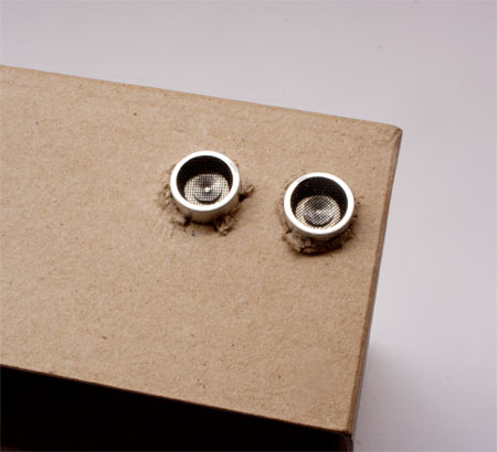 Making holes for the ultrasonic sensor
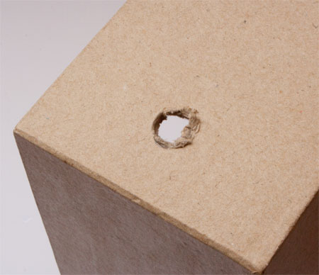 Cutting hole for power cord
Prepare the Pan & Tilt Servos
Two servos animate Deskbot Pal’s head, making it bob back and forth, and turn side side-to-side. You need a hot melt gun for these steps. You can use either a low temperature or high temperature gun, but remember that the glue oozing from a high temp gun is especially hot. Both kinds of glue guns can burn you, but melted glue from a high temperature gun can cause serious burns. By mounting two servos at 90 degrees from one another, one will act as a tilt motor, and the other will serve as a pan motor.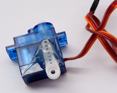 Mounting a horn on the pan servo
 Mounting horn on bolt
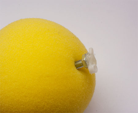 Bolt inserts into the foam ball
Note: If you’re using a high density Styrofoam ball, try to screw the bolt into the hole, rather than just pushing it in. Otherwise, the bolt may simply break through the foam, making a large (and useless!) hole.
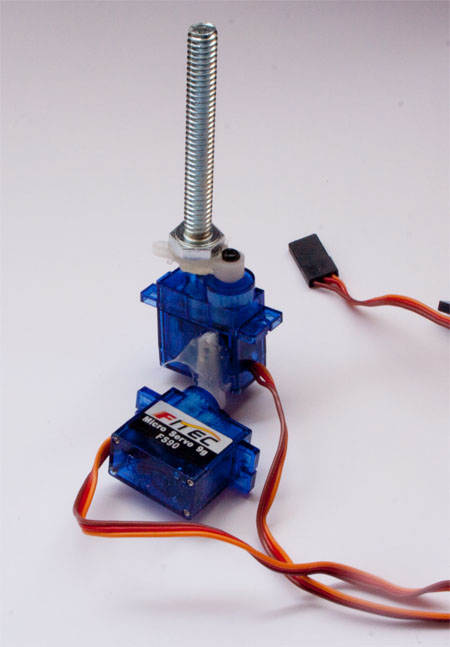 Assembled pan/tilt servo
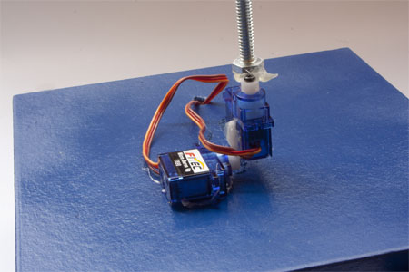 Pan/tilt servos glued to the enclosure
Tip: Remember to glue on the servos so that the pan motor, is over the center of the box. Don't glue the tilt motor onto the center, or else your Pal will sit on the box lopsided!
Wire the Pan and Tilt Servos
With the servos mounted to the enclosure: 1. Snake the wires from both servos into the box through the hole you made on the top. 2. Apply a 1” by 1” square of double-sided foam tape to the underside of the Itead Leonardo, and use it to stick the board into the approximate center inside the box. Position the long row of 3-pin headers near the hole on the top of the box. Of course, be sure not to cover up any holes. Electrical connection for the servos
Tip: Servo wires uses color coding. The brown (or black on some servos) wire is connected to the “G” pin of the 3-pin header. G means ground.
Mount and Wire the Ultrasonic Sensor
As with the servos, you’ll use a hot melt glue gun to mount the ultrasonic sensor into the enclosure. For this initial version of the Deskbot Pal, you’ll only wire up one ultrasonic sensor; in an upcoming installment, you’ll add a second one, to give your Pal stereo vision.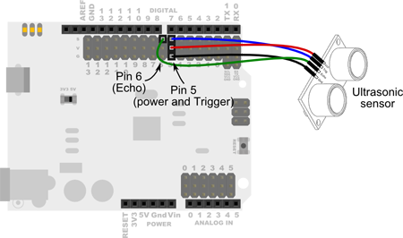 Electrical connection for ultrasound sensor
Warning: Be absolutely certain not to cross the connections to the sensor. Be especially sure you don’t mix the G and V pins on the 3-pin header, or else you could damage the sensor, and possibly your Itead Leonardo board! The G (for ground) and V (for V+) are the power connections, and mixing them up can lead to bad things.
2. Position the ultrasonic sensor inside the enclosure so that its transceivers poke through the holes you previously cut. The 4-pin connector of the sensor should point down, to provide easy access to the wiring. 3. Apply a very small dab of hot melt glue to one or both sides of the sensor, to keep in place. 4. You may wish to cover up the mounting holes for the ultrasonic sensor using a bezel or other decoration. For the prototype, I fashioned the bezel myself, but RobotShop provides an acrylic laser cut version for your convenience.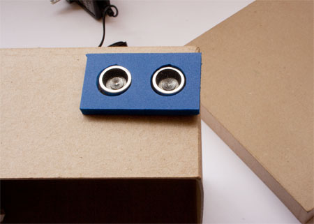 Bezel for ultrasound sensor
Mount and Wire the Side Switch
A switch mounted on the side of the Desktop Pal serves as a kind of mode setter. I’ll explain its full use in a future blog post. For now, let’s just get ‘er installed! 1. Lead the wire from the Crash Sensor switch through the hole you made on the side of the enclosure. 2. Cut a piece of double-sided foam tape to 1/2” by 1/2”, and apply one side to the flat underside portion of the switch. 3. Use the tape to affix the switch to the side of the box. The roller of the switch should be mounted so it just sticks out the front of the box.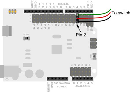 Switch electrical connection
Tip: The switch uses color coded wires. The black wire should go to the G (or ground) pin of the 3-pin header.
Insert Power Adapter Wire
Your Desktop Pal needs power, which comes from a small 7.5 volt wall adapter. 1. Insert the barrel end of the adapter through the hole you previously cut into the rear of the box. 2. Plug the barrel into the power jack on the side of the Itead Leonardo. 3. Making sure there is enough slack to work with, apply some hot melt glue to the wire as it comes into the rear of the box.Warning: Don’t plug in the power adapter quite yet.
Verify All Wiring
Before proceeding, take the time now to verify that everything is connected to where it should be.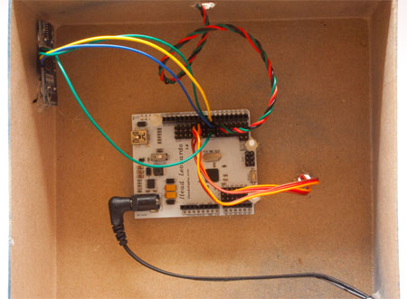 Internal wiring
- Pan and tilt servo connections
- Ultrasonic sensor connections
- Crash Sensor switch connection
- Power adapter
Tip: Now’s a good time to insert a programming cable into the Itead Leonardo. Since these cables are fairly inexpensive, consider just keeping it attached to the board. When not in use, coil up the cable, and tuck it inside the box.
Decorate and Install the Head Ball
Desktop Pal uses decorations of your choice, so this next part is completely up to you. For my prototype, I began by cutting off the legs of a stuffed animal, and pinning them – with safety pins – to the underside of the foam ball.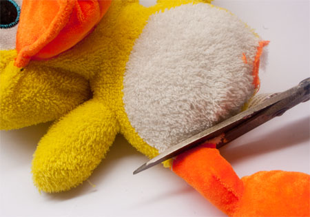 Use old toys for decorating
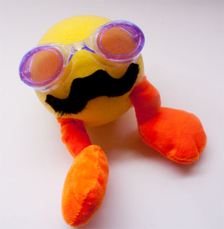 Desktop Pal head
Coming Up…
In the next installment, you’ll learn how to calibrate and test the servos, ultrasonic sensor, and switch, and make your Desktop Pal do rudimentary functions. Since this might be the first time you’ve used an Arduino microcontroller, I’ll cover how to set things up so you can begin programming with it. The Itead Leonardo is a 100% compatible Arduino board, but its setup is a little different from the typical Arduino.Thanks for helping to keep our community civil!
This post is an advertisement, or vandalism. It is not useful or relevant to the current topic.
You flagged this as spam. Undo flag.Flag Post
Your post is currently under review by our moderation team. The review process usually takes up to 48 business hours.
You can track your post's status in the "My Content" section of your profile. Once approved, it will be published and visible to others.

Thank you for contributing to our community!