

Adding a Shaft Encoder Directly Into A Servo

Here's a nifty hack to add a shaft encoder directly into a servo box.
Parts:
1. Servo -
Preferrably a Futaba or Tower Systems
2. Drill
3. Photointerrupter
- Rat. Shack #276-142 (NOT the package with the diode and transistor
separate),
or any standard 'U' shaped photointerrupter - Available in
most printers, VCRs, etc.
4. Hot glue
5.
Potentiometer
Background:
For most of the time
that I've been doing amateur robotics I've always wanted to have some
kind of feedback from my motors. Such set up would allow for dead
reconing and accurate turning and other manuvers without having to worry
to much about in-code timing or battery voltage. Unfortunately I've
never been able to figure out an effective and cheap way of setting up
such encoders.
A few months ago I started a science fair project
about using a maze solving robot. After a few days of planning it became
apparent that I would need wheel encoders for one of the robot's maze
solving algoritms. I briefly considered putting an interrupter across
the spokes of the wheels. I soon ditched that idea because it was
unreliable.
Soon after I realized my need, I saw a brief
show-and-tell at the Triangle Amateur Robotics club. Ken Boone showed
how he was going to add a built-in encoder to his micro servo. He
planned on drilling holes through the metal gears, then positioning a
photointerrupter across the gear to count the holes. I thought this was
rather innovative, but didn't consider the idea feasible for my
application.
A month or so after that I picked up a copy of Karl
Lunt's Build Your Own Robot from the local library. We went camping that
weekend, and most of my time was spent devouring the book. In it Karl
describes how he added a built-in encoder to his servo, by setting up a
photoreflector on the bottom most gear of the servo. Karl's idea sounded
more reasonable to me, because I thought that I would be able to change
out the shaft gear after the modification was done. By being able to
change the shaft gear I could convert the modified servo back to a
regular servo at a moments notice. Ken's idea sandwitched the shaft gear
between the diode and transistor, thereby trapping the gear. It was only
after I started the modification that I realized that Karl's idea would
do the same. Karl's idea generated about 140 pulses per revolution,
where Ken's only generated 6 per revolution.
When I got home I
quickly dismantled my servo and began to add an encoder ....
Modification #1 - The Frustration

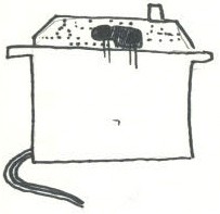
Karl added an encoder to his servo by first drilling a hole
into the case above the bottom most gear of the servo. Karl was using on
of the standard Futaba servos. Fortunately my Futaba 3003s were exactly
the same. The position of the hole was critical in the design. Karl
using a Semens IR photodiode/phototransistor built-in pair. This allowed
for a very small package. But, I didn't have that luxery. My mission
then was to find some good IR photodiodes and photo-transistors.
Fortunatly the search was short lived.
Back in the early days of
my robotics endevors I nievely bought 2 photointerrupters from Radio
Shack. I had held the idea that they could be used in an IRPD setup.
After learning of my mistake I had tossed the diodes and transistors
into my 'junk box.' Amazingly enough the diodes and transistors were
very small and perfect for my application. I drilled holes into the side
of my servo case until I was able to position the diode/transistor pair
above the bottom most gear. This is the gear that directly connect to
the small gear on the motor. It is large, flat, and has a whole bunch of
teeth.
I inserted the photodiode between the
shaft gear and the bottom gear, and positioned the phototransistor
directly above the bottom gear and below the top-middle gear. That way
the infrared light would bounce off the bottom gear and hit the
transistor.

I then took a 'Sharpie' marker and marked
1/4 to 1/3 of the bottom gear black.
I
made sure that the mark was as dark as possible. The idea was to have
the dark part absorbe most of the IR light, thereby preventing it from
reaching the transistor, thereby causing a large change in the
phototransistor's resistance. Good idea in theory but hard to implement.
After much trial and error I was able to get the phototransistor
to generate about a 50k resistance differenace between light and dark.
At that point it was rather late at night and I decided to go to bed. I
woke up that morning, and in my excitement I decided to hook it up again
and test it. Being overly eager I bypassed the current limiting resistor
on the diode and ... *pop* it was dead.
That normally wouldn't
have been so bad, except for the fact that the only other IR photodiode
I had, that was near the other's size, was just slightly too big to fit
between the bottom gear and the shaft gear. Oh well, I just decided I'd
move it up beside the phototransistor. 
I
tired and tried with this setup to get an acceptable resistance
difference, but alas and alack it wasn't going to happen. At this moment
of desperation I decided to take my Dremel tool and shave down the
surface of the diode, so it would fit where the othe one had. Even after
all of that I was still unable to get the desired change in resistance.
It was time for another idea ....
Modification #2 -
Finally!
To prevent the risk of premature baldness I decided
to try out Ken's modification idea. Actually, as I later found out, his
idea is a bit different. See the note at the end of this article.
Thankfully this worked much better. Below are the steps describing the
modification:
1. Remove the main/shaft gear from the gear train.
Around the perimeter of the gear, inside the line of teeth, you should
be able to make out 6 small circualr formations, that were created when
the gear was molded. This 6 circles make perfect outlines for drilling
holes. Find a good bit for the job and put 6 holes though the
gear.

2.
Replace the gear back in the housing and drill a hole for the diode and
transistor above and below the gear.

3. If you need more room you can shave the gear down a bit. Most
gears have a ridge around the outside that can be shaved down to make
more room. Place the photodiode and transistor above and below the gear
so that they face each other. Hot glue them in place and make sure that
they don't hamper the movement of the gear.
4. Put a resistor in
series with the the photodiode and power it up. Measure the resistance
of the phototransistor as you turn the shaft. Make sure that your have
the negative lead of your multimeter hooked up to the negative lead of
the transistor and the same for positive. Reversing the leads causes the
resistance to be very high. You should be able to get a sizeable
resistance difference. Usually above 50k ohm. If the resistance doesn't
change that much you can try adding foil backing to the gear then puch
holes through it.
5. Hook up the transistor to the schematic
below.

6. Now, turn the shaft till you reach
highest reistance. This means that it is not above the hole. Measure the
resistance across the transistor and find a potentiometer that is about
twice that value. Connect up the pots middle pin to Vin and one of the
wipers the to the transistor '+'. Measure the voltage across 'Vin' and
the pot/transistor connection. Turn the pot till the voltage is greater
than 2.7 or so volts. Now turn the servo shaft till the diode/transistor
pair is over a hole. The voltage at this point should read below 1.5v.
Measure the resistance of the pot and insert a similar value in its
plce. If you prefer to do this process by manual calculations use this
formula to figure out the resistor value:
Vout = Vin (R2
(R1 + R2))
In this case Vin is 5v. R2 is equal to the
resitance of the transistor and R1 is what you are trying to figure out.
You will want the Vout to swing from at least 1.5v to 2.7v. You should
probably check the specification of your chip to make sure that this
voltage swing will generate a pulse.
This is a note I received
from Ken. He's clarifying his idea a bit. It seems that I got it a bit
wrong.
My conversion uses the same bottom gear you started
with. It has 8 holes through it and aluminum foil on the bottom to
completely block the IR. There is around 320 pulses per revolution of
the output gear. The detector in below the gear inside the bottom case
and there is a ground down IR LED suspended above the gear. I get a sine
wave output and I use [a custom] circuit for line detection... My goal
is to do speed control on each drive servo so I can accurately go
straight and accurately do several different sweep turns with the fire
fighting robot. I also want to count the pulses to accurately rotate the
robot and determine how far it has gone.
Well, there you
have it! A nice compact encoder inside your servo. It's just wating to
be hooked up to your Stamp's PULSIN command or your OOPic's oCounter
object.
Update - Modification #3 - Hopefully the
last!
Well, after hours and hours of agonizing work I finally
just gave up and decide to switch gears (pun intended). I finnally
realized the obvious truth - 6 counts per wheel just won't work! As per
Ken's hack I decide to move the photointerrupter to the bottom gear. I
drilled 4 holes into it. Be careful not to crack the gear - I speak from
experience. And drilled out the top of the bottom part of the case. And
placed a red LED (my IR went dead) at the top and put a phototransistor
in the bottom. This gives me about 180 counts per revolution. I put
black electrical tape and black perminant marker to block the light
going throug the gear.
Thanks for helping to keep our community civil!
This post is an advertisement, or vandalism. It is not useful or relevant to the current topic.
You flagged this as spam. Undo flag.Flag Post
Your post is currently under review by our moderation team. The review process usually takes up to 48 business hours.
You can track your post's status in the "My Content" section of your profile. Once approved, it will be published and visible to others.

Thank you for contributing to our community!