

Programming DAQs using FlowBotics Studio & FlowStone


 In this tutorial we are going to cover Data Acquisition boards (or DAQ’s as they are better known) and how to program them using FlowBotics Studio which uses the FlowStone graphical programming language inside.
Signal Types and Levels:
The signal types for DAQ boards usually come down to analogue or digital, but in order to get your data processed correctly there is usually some form of signal conditioning necessary and this is usually hidden deep in a data sheet somewhere. For Example: A digital input: 0 or 1 but what signal level represents a '0' or a '1' and what is the maximum voltage? If the voltage goes over will it fry the board etc.So here is a rough guide to signal conditioning for DAQ’s:Digital Inputs:
Inside FlowBotics Studio, digital inputs are represented as "Bool" (Boolean ie. true or false) and on the DAQ board this will be a DC voltage, usually referred to as "TTL" or "CMOS" together with a max voltage figure (ex. 5V TTL). TTL is usually 5V and CMOS is usually 3.3V, however this is not always the case so you will need to check the data sheets; it could be 3.3V, 5V, 12V, or 24V for either! So let’s say you have a simple switch, switching a signal from a 12V battery, and the input is 5V TTL. Usually there is an absolute max voltage, say 5.5V for a 5V setup, which, if exceeded, will damage the board. Also, the OFF state is usually around 50% of the ON state, so in this case anything < 2.5V will be read as a 0 and anything >2.5V will be read as a 1, again this can vary! It’s pretty clear that if we connected the 12V signal into a 5V board, there would be smoke! This is where signal conditioning comes in; we need to drop our 12V signal to 5V, but how? The solution is to use a "Potential / Voltage Divider". Essentially this involves two external resistors connected in series where the 12V signal connected to one end, the 5V signal is tapped from the junction, the other end is then connected to ground. This simple circuit works perfectly with DAQ devices as the current required by the TTL or CMOS inputs is so low it becomes negligible in the math. Using Ohms law you can calculate the resistor values as follows:Vout = R2 x Vin
R1+R2
So in our example for ease of math we could use a total resistance of 12Kohms, R1 = 7K and R2 = 5KVout = 5000 x 12 = 5.00 V
12000
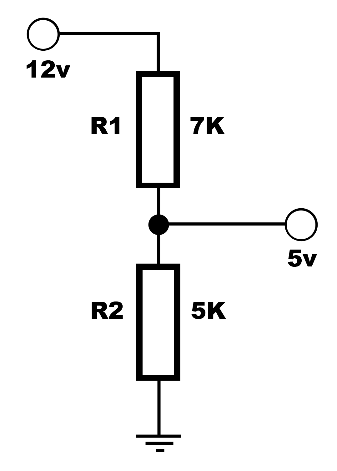 In reality the resistor values might be slightly different as they come in odd values like 4.7K and 7.2K, which is ok as long as the absolute max voltage isn’t exceeded:
Vout = 4700 x 12 = 4.73 V
11900
Analogue Inputs:
Analogue signals are usually fed into a device called an "Analogue to Digital Converter" (or A/D for short). This device converts a varying voltage into a number which can be used inside FlowBotics. A/D converters suffer from the same voltage restrictions as the digital inputs and to compensate for this, they usually provide a stabilized reference voltage to help with the signal conditioning. Again a potential divider circuit can be used to drop a higher voltage to the reference voltage. Frequently A/D converters use a reference like 3.3V so you will need to check the data sheet to see what it is for any given board. There are also other considerations when providing signal conditioning for A/D converters; there is the "Dynamic Range" (what it the biggest number that can be represented), is it "polar" or "bi-polar" (is it just positive signals (0-3.3V) or positive and negative (+3.3V to -3.3V)), and finally the sampling rate (what is the maximum frequency your can read; 1hz, 100hz, 1Khz etc.?).Reference Voltage:
This is usually a stabilized and very accurate voltage to be used as the A/D reference. This is usually the maximum voltage the A/D can read.Dynamic Range:
Dynamic Range is the difference between the largest and smallest signals. Usually described in "Bits" (8-bit, 10-bit, 16-bit, 24-bit etc.), this is the maximum number / limit of the signal resolution. You can calculate the actual maximum number using 2 to the power of the bits (2^b where b= bits). For example 8-bit resolution would be 2^8 = 256, 10-bit would be 2^10 = 1024, 16-bit would be 2^16 = 65536 and so on. You can see that the dynamic range is very important if you want a lot of resolution. To illustrate this imagine a vibration sensor on the Space Shuttle; when it launches, the vibration will be huge, but in Space everything is calm. Let’s say Launch = 90% of the full signal and in Space the signals are only 1%. So if you want to detect any minor vibrations in space you will need a large Dynamic Range to read both large and small signals. Say you used an 8 bit A/D converter, that would give you only 256 values between the largest and smallest signal, so in space the reading would be only be a maximum of around 3 values - very bad resolution! If we then used a 16-bit A/D (65536 values) this would give you 655 possible values at the low end to read the signals. Now imagine a 24 bit converter (1677216 values) the low end signal would have 167,000 values!Sampling Rate:
Sampling rate; this is how many times a second the signals are read and this dictates the maximum frequency of an input signal.This is defined by the "Nyquist Rate" and states that the minimum sampling rate must be 2x the required bandwidth. Or the other way round the maximum frequency you can read is ½ the sampling rate. If you want to read an analogue signal at 1000Hz you will need to sample at a minimum of 2000Hz in a digital system. Another good example is CD music, the sampling rate is 44.1Khz so the maximum audio frequency is 22050Hz.Anti-Aliasing:
"Aliasing" is an erroneous reading produced by the A/D by sending signals of too high a frequency to an A/D converter, basically above the Nyquist Rate. This is similar to looking at the propeller of a plane spinning, at some speeds the propeller appears to be stationary or moving slowly when in fact it is spinning really fast. In our case of an A/D converter imagine sampling at 1000Hz and then connecting a sine wave signal at 2000Hz, depending on the phase of the signal you could read all zeros or all ones or if it drifts slightly you could see a low frequency wave. The long and short of it is that if your analogue signals can go higher in frequency than the sampling rate then you should add an anti-aliasing filter to limit the bandwidth!Timer Inputs:
Timer inputs are used for accurate timing when the signals used are too fast for the PC. A timer will typically have a start and a stop trigger and the timing will be done on the DAQ board itself. Once captured only the result is passed into FlowBotics allowing very accurate timing with little overhead on the PC.Outputs:
The outputs of a DAQ board are also sensitive to how they are connected, the main issue being the load current. All outputs have a max load current value, and if exceeded, you can fry the board so care is necessary.- CMOS outputs: usually very low current and used to connect to other CMOS devices say < 1mA
- TTL output: can also be connected to other TTL devices but can sometimes deliver a little more current say 10mA (usually enough for an LED)
- Buffered outputs: usually buffered to deliver much higher currents, often enough for a relay say 100mA+
- Relay outputs: already buffered and have a relay connected to isolate the output altogether, again relays have max ratings so take care.
Digital Outputs:
The usually go from 0V to the supply voltage (say 5V) and are controlled via a BOOL output inside FlowBotics.PWM Outputs:
PWM (pulse width modulation) outputs are pulses of signal where the value is the width of the pulse. This is in fact how servos and motor controllers work. In the case of a DAQ, it is usually used for some form of motor controller where PWM is required to control the speed. In FlowBotics, a single number representing the pulse width is output and the DAQ board does the rest making it far more accurate and less load on the PC.Analogue Outputs:
Analogue outputs come from a digital to analogue converter (or D/A) and deliver an analogue voltage from a "Float" (type of variable) input inside the software. As before, there is usually a reference voltage output to give you the maximum voltage of the D/A.Programming DAQ’s:
So we now have an idea how to condition the signals correctly for our DAQ, now let’s look at the programming inside FlowBotics Studio. The benefit of using a language like FlowBotics is that you can use your PC to display the values of the inputs live and also make fast decisions based on the signals and feed them back to the outputs or record them to disk etc. You can even add a fully custom user interface (GUI) and make a .exe (executable file) out of your program to sell or distribute it.FlowBoard DAQ:
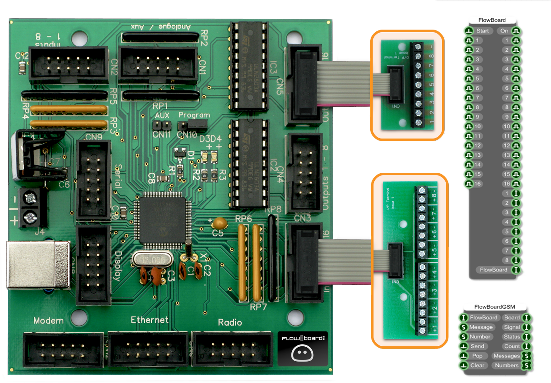 The FlowBoard DAQ is available from DSPRobotics and is a universal DAQ board with 16 Digital ins, 16 Digital Outs, and 8 Analogue (10 bit) ins, plus optional cell phone SMS sending and receiving! The great thing about this DAQ is that you can add optional boards to provide most of the signal conditioning, like an external 8 channel relay board, an LED board, or an Opto Isolated input board. There is a pre-programmed module inside FlowBotics Studioso it’s plug and play.
Phidgets 8/8/8:
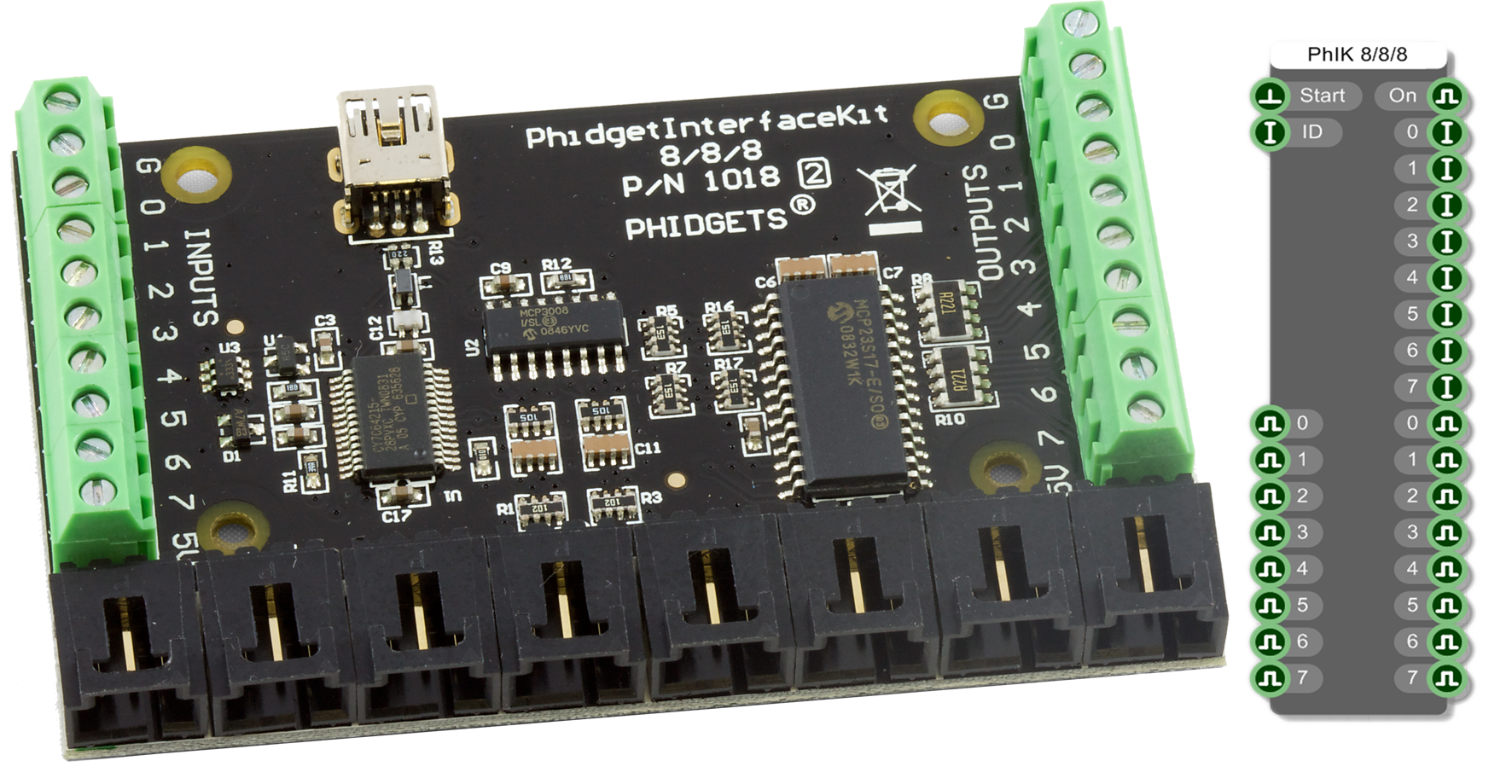 There are several Phidgets DAQ’s to choose from that are supported inside FlowBotics Studio, the 8/8/8 is one of the most popular with 8 analogue (10 bit) ins, 8 digital ins and 8 digital outs. Another great thing about the Phidgets line is the amount of external pre-wired sensors you can connect directly to the board with confidence that the signal conditioning is already done! Inside FlowBotics Studio there is a pre-made module so there is no programming necessary, you can even specify an IP address if you are using this over a network on another PC!
Measurement Computing 1208-FS & MC-1608-FS:
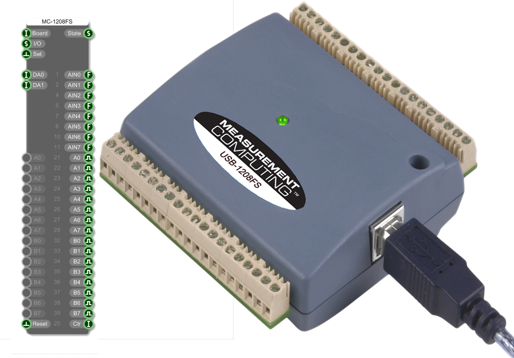 Measurement Computing make several hi-quality DAQ devices and currently the 1208-FS & 1608-FS are supported in FlowBotics Studio. These differ slightly compared to other DAQ’s as the IO configuration is programmable. Both boards have 16 configurable digital I/O pins, counters/timers, 8 analog inputs and some analogue outputs the main difference between the 1208 & 1608 is the dynamic range 12-bit or 16-bit. To program the I/O configuration you need to supply a string to the I/O input of the component. This should be a comma separated list of any combination of the following:
- SE - single ended analog inputs
- D - differential analog inputs
- AI - set bank A of digital I/O to be inputs
- BI - set bank B of digital I/O to be inputs
- AO - set bank A of digital I/O to be outputs
- BO - set bank B of digital I/O to be outputs
- Etc.
LabJack U3 HV & LV:
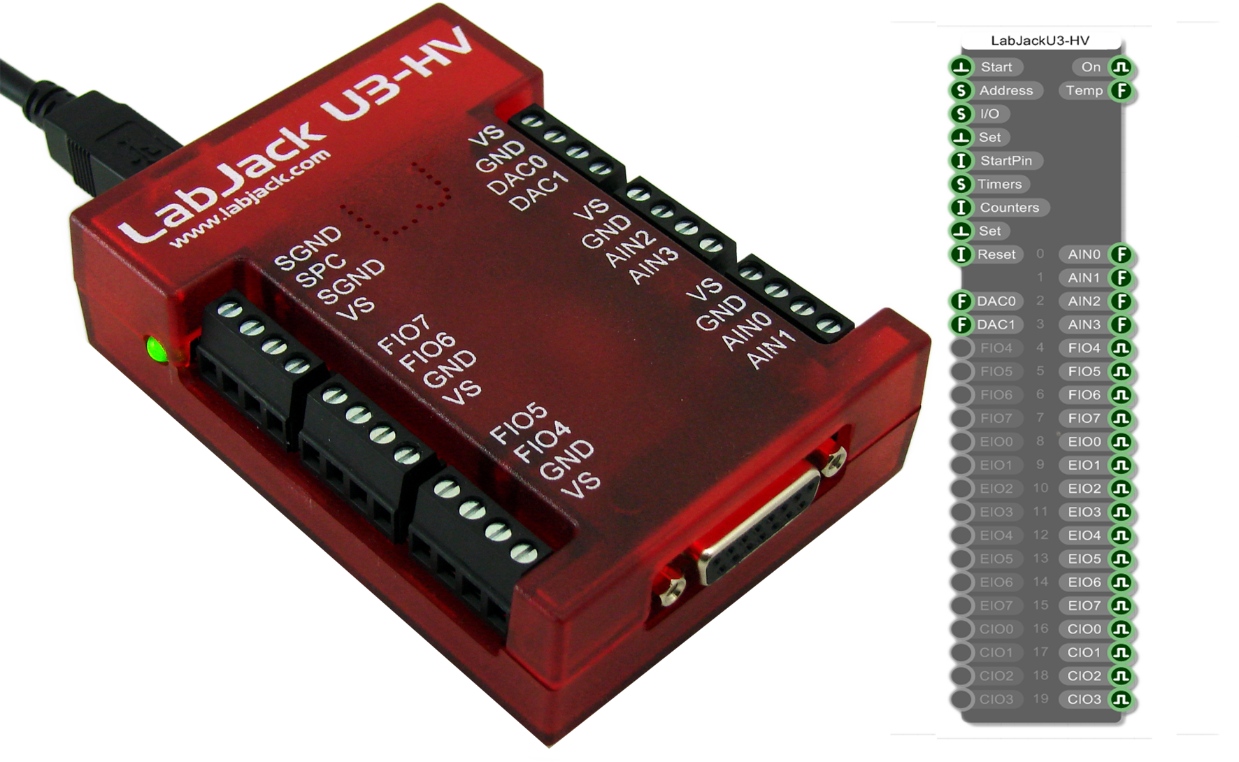 The LabJack U3 is a very versatile DAQ device that is also programmable. This DAQ has 16 flexible I/O pins and 4 fixed analog inputs, these are again programmed through a control string. To set the I/O you need to supply a comma separated string or a new line separated list of strings in a Text component to the I/O input. Each entry defines the format for a particular I/O pin. The entry starts with two characters to determine the type and direction: "DI", "DO" or "AI" for digital in, out and analog in respectively. In the case of analog it defaults to single ended but you can set the negative channel with a minus symbol followed by "SE","SP","VR" (single ended, special (0-3.6v or -10/+20v), internal voltage ref) or the number of the pin you want to have as the negative channel.
Starting Point Systems uChameleon:
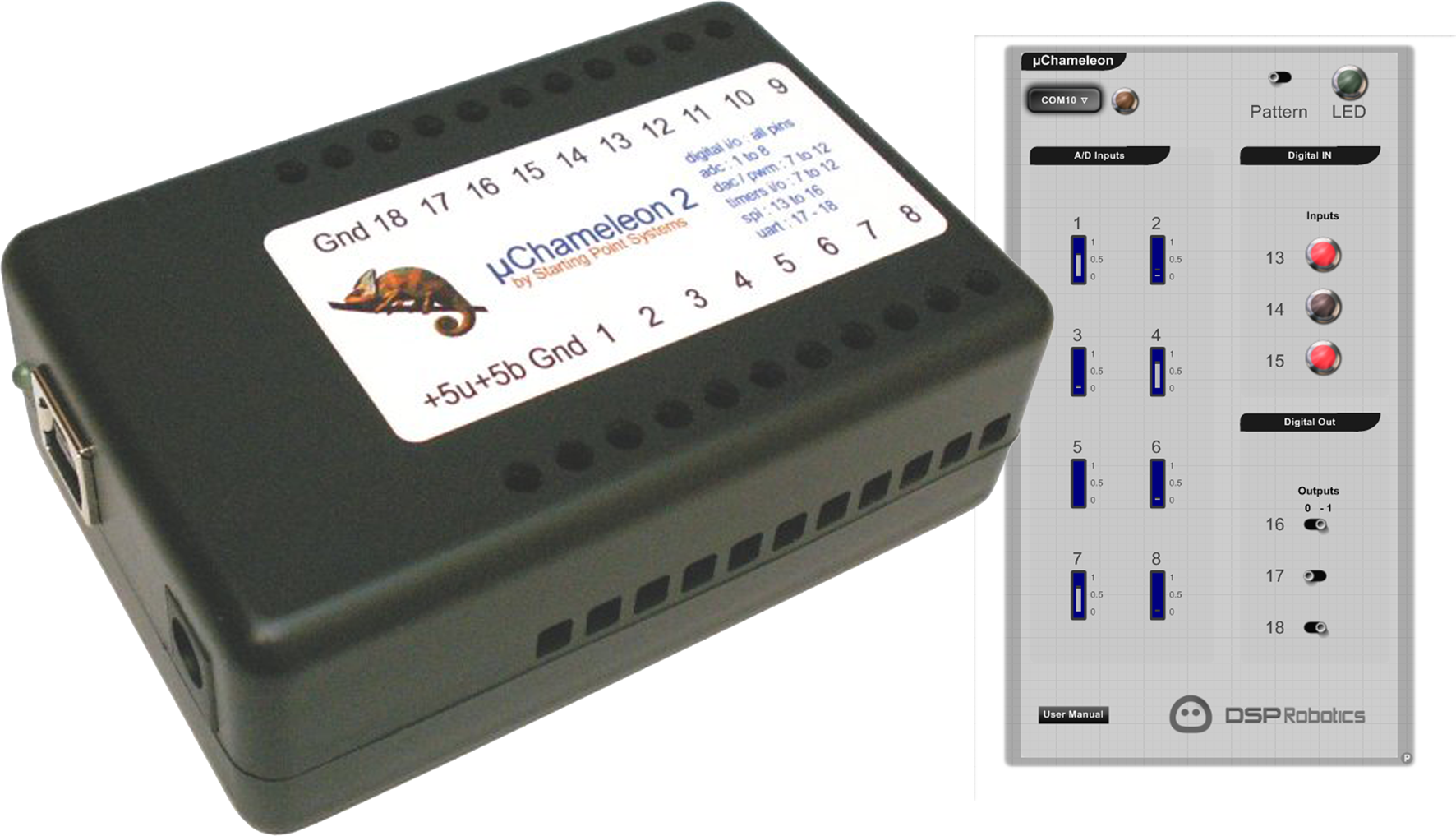 The uChameleon is what it says a bit of a chameleon as it can also be configured to your needs. This DAQ has18 general purpose I/O's, 8 Analog inputs, 4 Analog outputs, 4 Timer channels, 1 SPI 3-wire serial port, 1 UART serial port.The configuration is software programmable and is programmed through a virtual com port in FlowBotics. We have made a little test application that you can play with to see how to set it up and get the data in and out.
These are just a few examples of some DAQ devices that work with FlowBotics Studio. There are many more DAQs available from RobotShop.
More information on FlowBotics Studio can be found here: www.FlowBotics.com
The uChameleon is what it says a bit of a chameleon as it can also be configured to your needs. This DAQ has18 general purpose I/O's, 8 Analog inputs, 4 Analog outputs, 4 Timer channels, 1 SPI 3-wire serial port, 1 UART serial port.The configuration is software programmable and is programmed through a virtual com port in FlowBotics. We have made a little test application that you can play with to see how to set it up and get the data in and out.
These are just a few examples of some DAQ devices that work with FlowBotics Studio. There are many more DAQs available from RobotShop.
More information on FlowBotics Studio can be found here: www.FlowBotics.com
Thanks for helping to keep our community civil!
Notify staff privately
You flagged this as spam. Undo flag.Flag Post
It's Spam
This post is an advertisement, or vandalism. It is not useful or relevant to the current topic.
Report Reason
This post is an advertisement, or vandalism. It is not useful or relevant to the current topic.
You flagged this as spam. Undo flag.Flag Post
✅ Your Post Has Been Submitted Successfully!
Your post is currently under review by our moderation team. The review process usually takes up to 48 business hours.
You can track your post's status in the "My Content" section of your profile. Once approved, it will be published and visible to others.

Thank you for contributing to our community!