Operational amplifiers, also known as op-amps, are basically voltage-amplifying devices designed to be used with components like capacitors and resistors between their input and output terminals. Feedback components like these are used to determine the operation of the amplifier.
Op-amps are linear devices that are ideal for amplification and are used often in signal conditioning, filtering, or other mathematical operations (addition, subtraction, integration, and differentiation), giving it the name “Operational Amplifier”.
They are also quite affordable, with most general-purpose amplifiers selling for under a dollar a piece. Modern designs have been engineered with durability in mind as well. Several op-amps are manufactured in a way that can sustain direct short circuits without damage.
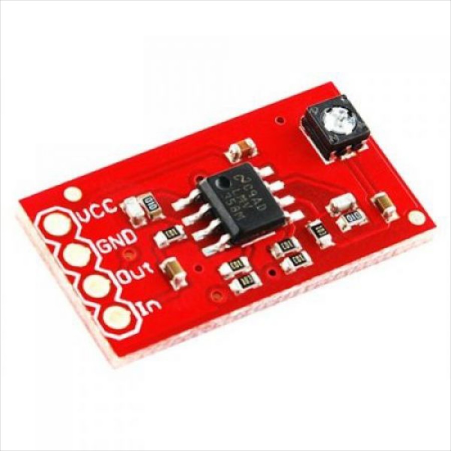
Source: RobotShop
Hearing aids are a perfect application of amplifiers. They use a microphone to pick up sounds from the external environment, which then get turned into an electrical signal. Inside this hearing aid, there’s an amplifier that takes that signal, boosts it up to make it louder, and sends it to a speaker resting inside your ear canal.
This entire process of taking an input signal, amplifying it, and sending it onward as an output signal is the essence of amplifier circuits. The boost that an amplifier produces for a given signal is the gain ( A ). This is simply the difference in voltage between an input signal and an output signal. For example, if you start with 1 V at your input, and get 5 V at your output, then you have a gain of 5.
What Makes an Op-Amp Special?
While all amplifiers might have the same general purpose, when you need an ideal amplifier then you’d want to use an op-amp. Within analog electronics, nothing comes close to matching the ideal performance of an amplifier with amplification characteristics like:
- High gain: One of the most well-known features of op-amps is their very high gain, which can range from 10,000 to 100,000!
- High input impedance: Another key attribute is a high impedance, and the op-amps in production these days come with input impedances that are almost infinite, measuring in at 0.25 MΩ or even hundreds of millions of ohms.
- Low output impedance: In a perfect amplifier, you’ll get zero output impedance, and an op-amp is the only physical component that comes close to achieving this. You’ll find most IC-based op-amps having an output impedance of less than a hundredth of an ohm.
- Limited bandwidth: Op-amps also have a limited bandwidth, which can work in your favor. Many op-amp ICs used for audio applications only experience their complete gain over a small bandwidth. But in other circuits, you’ll be wanting to reduce that gain, which is where a limited bandwidth comes in handy.
Op-amp Connections
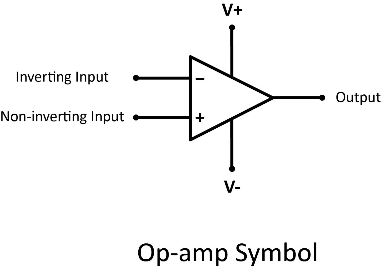
Regardless of its particular purpose, an op-amp always aims to deliver an output voltage raising or lowering input voltages until they are equal. But how does it make that happen? Let’s take a look at a typical op-amp schematic symbol to explain how it works.
Input Signals
An operational amplifier is basically a three-terminal device that consists of two input signals, an inverting input marked with a negative (-) symbol, and a non-inverting input indicated with a positive (+) symbol. When you have a signal on your inverting input, then you’ll get an amplified output that is the inverse, or the opposite of this signal. So, if a positive signal goes in, then your output will be negative. The non-inverting input works the opposite way. If you send a positive signal into a non-inverting input, then you’ll get an output that matches the input signal, just amplified.
Output Signal
On the other side of the schematic symbol for this op-amp is the output. This output takes the difference between both your inverting and non-inverting input signals to produce an amplified output signal until the input voltages are equal. This is why an op-amp is commonly referred to as a differential amplifier because it provides an output result based on the difference between the two input signals.
Power Signals
You also need to power your device. At the top and bottom of the op-amp symbol, you have a V+ and V-, which denote the positive and negative sides of a DC power connection. These power supply rails often won’t be shown in circuit diagrams since it’s assumed that they will always be connected. Whether you see them or not, you’ll find op-amps connected to a + (5 to 15) V and - (5 to 15) V power rail, all based on the specifications of the op-amp chip you plan to use.
Open-loop
In the open loop op-amp circuit, the non-inverting input is connected to ground, and an input signal is placed on the inverting input. In this arrangement, the voltage to be amplified is the same as the voltage of the inverting input.
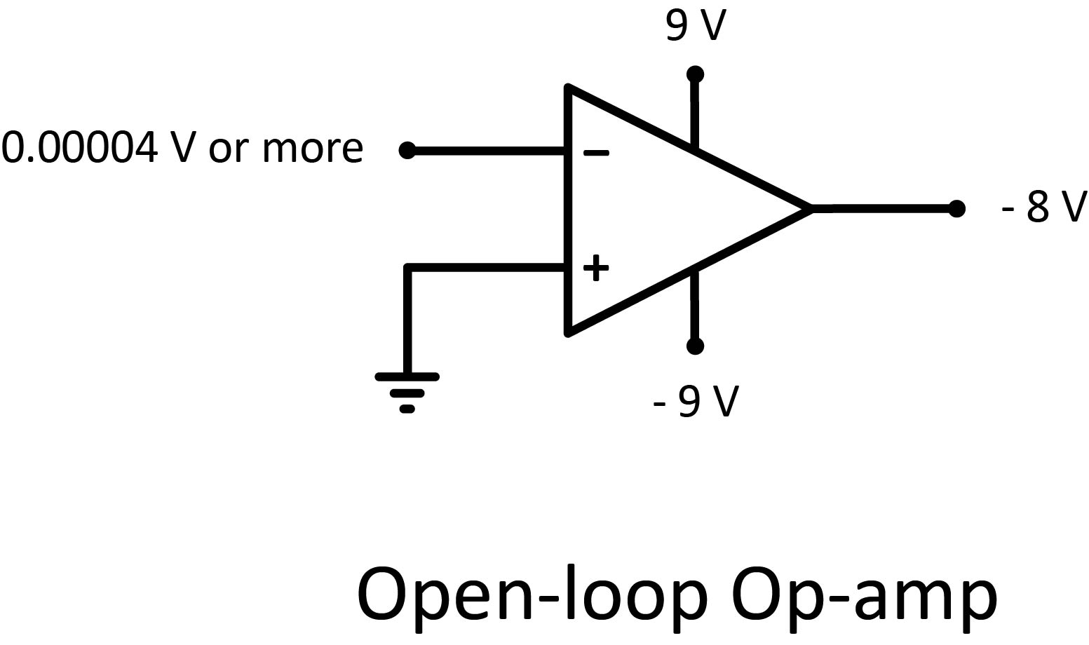
The voltage gain in an open loop op-amp circuit is extraordinarily high — on the order of tens or even hundreds of thousands.
Suppose that you’re using an op amp whose open loop voltage gain is 200,000 and that the power supply is 9 V. In that case, an input voltage of +0.000025 V will result in an output voltage of +5 V. An input voltage of +0.00004 V will give you an output voltage of 8 V.
The output voltage can never exceed the power supply voltage. In fact, the maximum output voltage is usually about 1 V less than the power supply voltage. So, if you’re using a pair of 9 V batteries to provide a 9 V power supply, the maximum output voltage is 8 V.
As a result, the most that an open loop op-amp circuit with an open loop gain of 200,000 can reliably amplify is 0.00004 V. If the input voltage difference is any larger than 0.00004 V, the op-amp is said to be saturated, and the output voltage will go to the maximum.
No matter how much money you invested in a top-quality voltmeter, it isn’t sensitive enough to measure voltages that small. So, for all practical purposes, 0.00004 V is the same as 0 V.
As a result, one of the basic features of an open loop op-amp circuit is that if the input voltage difference is anything other than zero, the op-amp will be saturated, and the output voltage will be the same at its maximum. So if the maximum output voltage is 8 V and the input is a sine wave, the output will be one of only three voltages: +8 V, 0 V, or –8 V.
Closed-loop
Open loop op-amp circuits aren’t very useful as electronic amplifiers because they’re so easily saturated. To make an op-amp useful as an amplifier, you must use it in a feedback circuit, which reduces the gain to a more manageable amount so that input voltages can be amplified reliably.
You’re likely already familiar with the concept of feedback. You’ve probably sat in an auditorium listening to someone talk into a microphone when suddenly a piercing screech came out of the speakers. That screech was feedback. In that case, the microphone picked up some of the output from the speakers and sent it back through the amplifier again. The result was an annoying high-pitched squeal.
Not all feedback is bad, though. In an op-amp amplifier circuit, feedback is used to reduce the enormous open-loop amplification gain to a more manageable gain. If the output of an op-amp is fed back to its inverting input and a voltage signal is applied to the non-inverting input, we would find that the output voltage of the op-amp closely follows that input voltage.
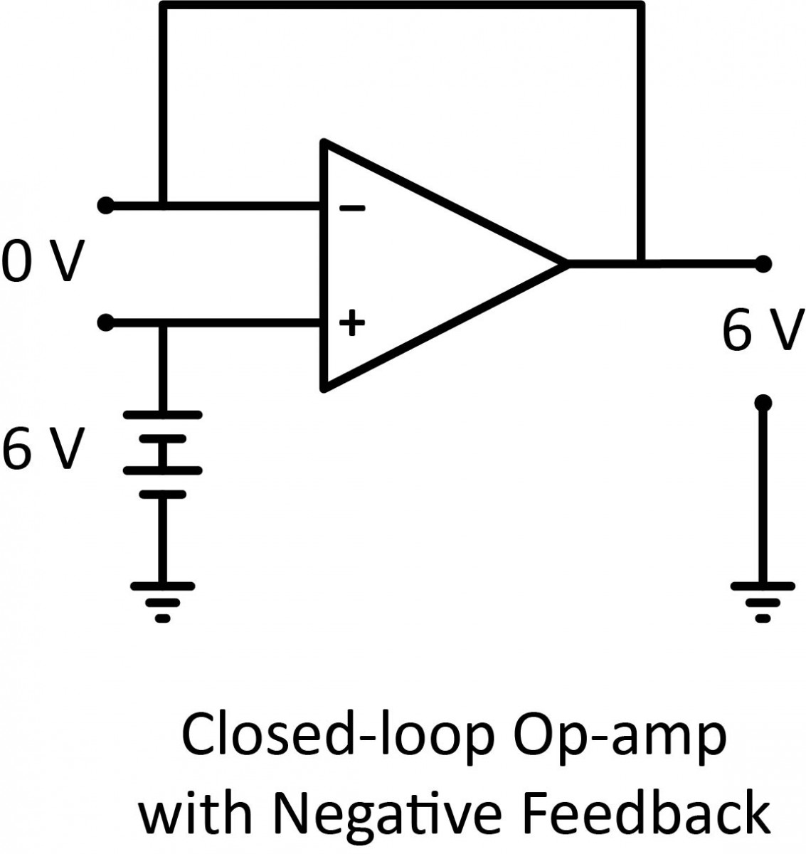
As the input voltage increases, the output voltage will increase in accordance with the differential gain. However, as the output voltage increases, that output voltage is fed back to the inverting input, thereby acting to decrease the voltage difference between inputs, which acts to bring the output down. What will happen for any given voltage input is that the op-amp will output a voltage very nearly equal to the input voltage, but just low enough so that there’s enough voltage difference left between the input voltage and the inverting input to be amplified to generate the output voltage.
The circuit will quickly reach a point of stability, where the output voltage is just the right amount to maintain the right amount of difference, which in turn produces the right amount of output voltage. Taking the op-amp’s output voltage and coupling it to the inverting input is a technique known as negative feedback, and it is the key to having a self-stabilizing system. This stability gives the op-amp the capacity to work in its linear (active) mode, as opposed to merely being fully saturated. Resistors are usually used to reduce the voltage that is fed back to the input.
One great advantage to using an op-amp with negative feedback is that the actual voltage gain of the op-amp doesn’t matter, as long as it is very large.
Op-amp gains, therefore, do not have to be precisely set by the factory in order for the circuit designer to build an amplifier circuit with precise gain. Negative feedback makes the system self-correcting. The above circuit as a whole will simply follow the input voltage with a stable gain of 1.
Op-amps have an extremely high gain that you won’t be able to change. This is why you’ll be adding feedback into your op-amp circuit with the addition of resistors, capacitors, or inductors to control the gain and get different results from your circuit. This addition of feedback loops also allows you to easily create variations on an op-amp circuit to get some widely different results. Here are the most common circuits you’ll be building when you first start out:
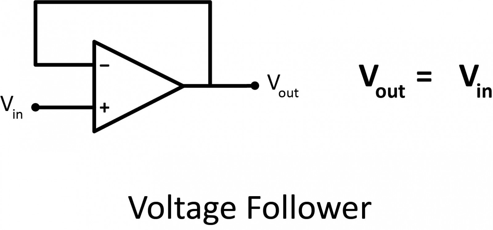
Voltage Follower
The most basic circuit is the voltage buffer, as it does not require any external components. As the voltage output is equal to the voltage input, students might become puzzled and wonder whether this kind of circuit has any practical application.
This circuit allows for the creation of a very high-impedance input and low-impedance output. This is useful to interface logic levels between two components or when a power supply is based on a voltage divider.
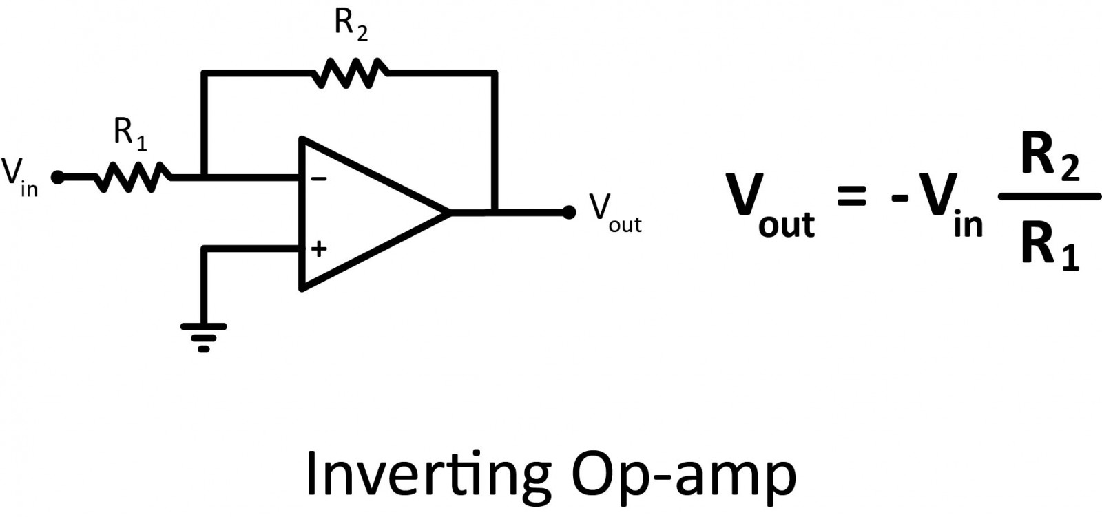
Inverting Op-amp
In this configuration, the output is fed back to the negative or inverting input through a resistor (R2). The input signal is applied to this inverting pin through a resistor (R1). The positive pin is connected to ground.
This configuration allows for the production of an output signal that is the opposite of the input signal.
Due to the negative sign, the output and input signals are out of phase. If both signals must be in phase, a non-inverting amplifier is used.
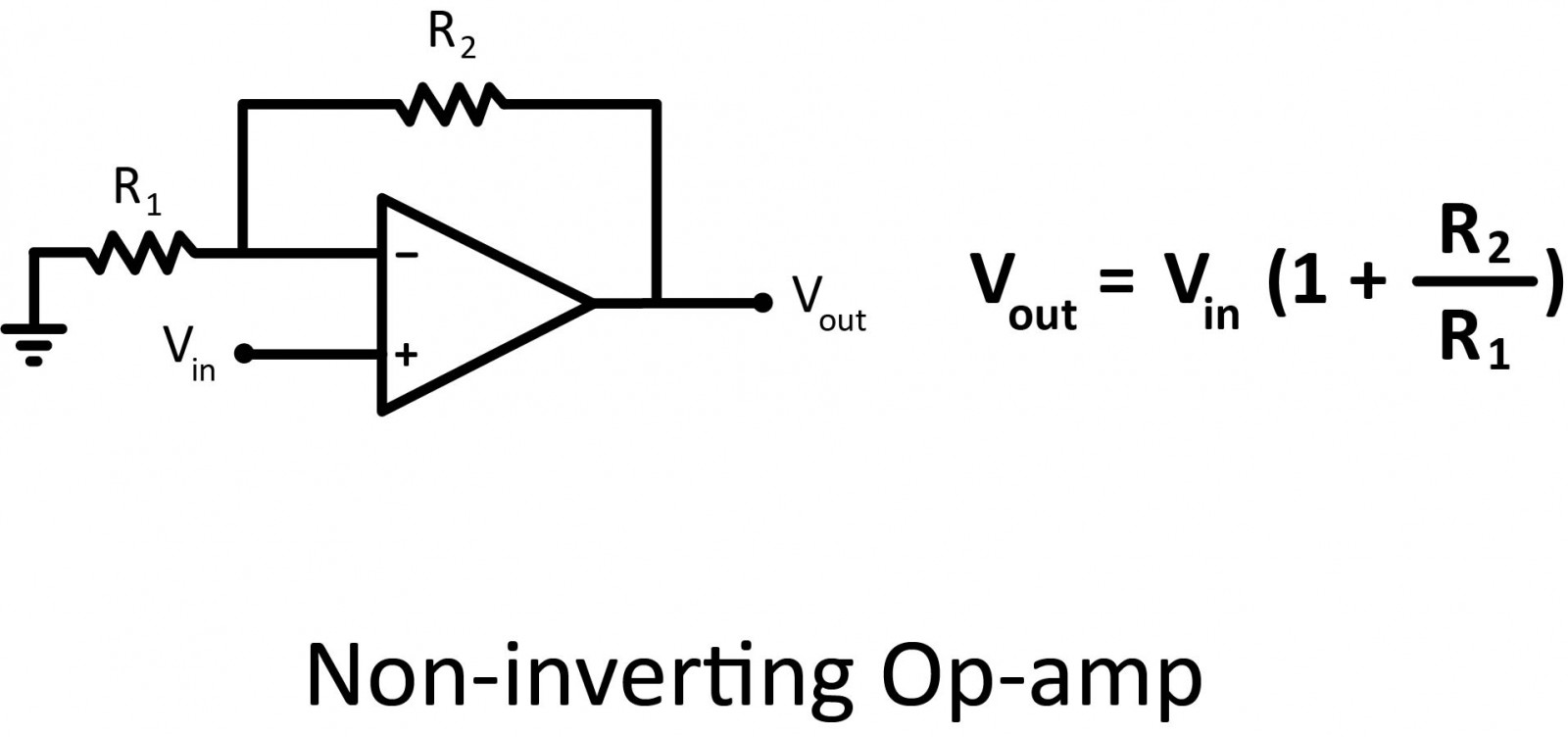
Non-inverting Op Amp
This configuration is very similar to the inverting operational amplifier. For the non-inverting one, the input voltage is directly applied to the non-inverting pin and the end of the feedback loop is connected to ground.
These configurations allow for the amplification of one signal. It’s possible to amplify several signals by using summing amplifiers.
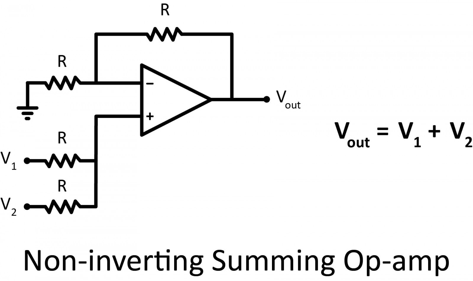
Non-inverting Summing Amplifier
To add 2 voltages, only 2 resistors can be added on the positive pin to the non-inverting operational amplifier circuit.
It is worth noticing that adding several voltages is not a very flexible solution. Indeed, if a third voltage is added with exactly the same resistances, the formula would be V out = 2/3 (V1 + V2 + V3).
So, the resistors would need to be changed to get V out = V1 + V2 + V3, or an alternative solution is to use an inverting summing amplifier.
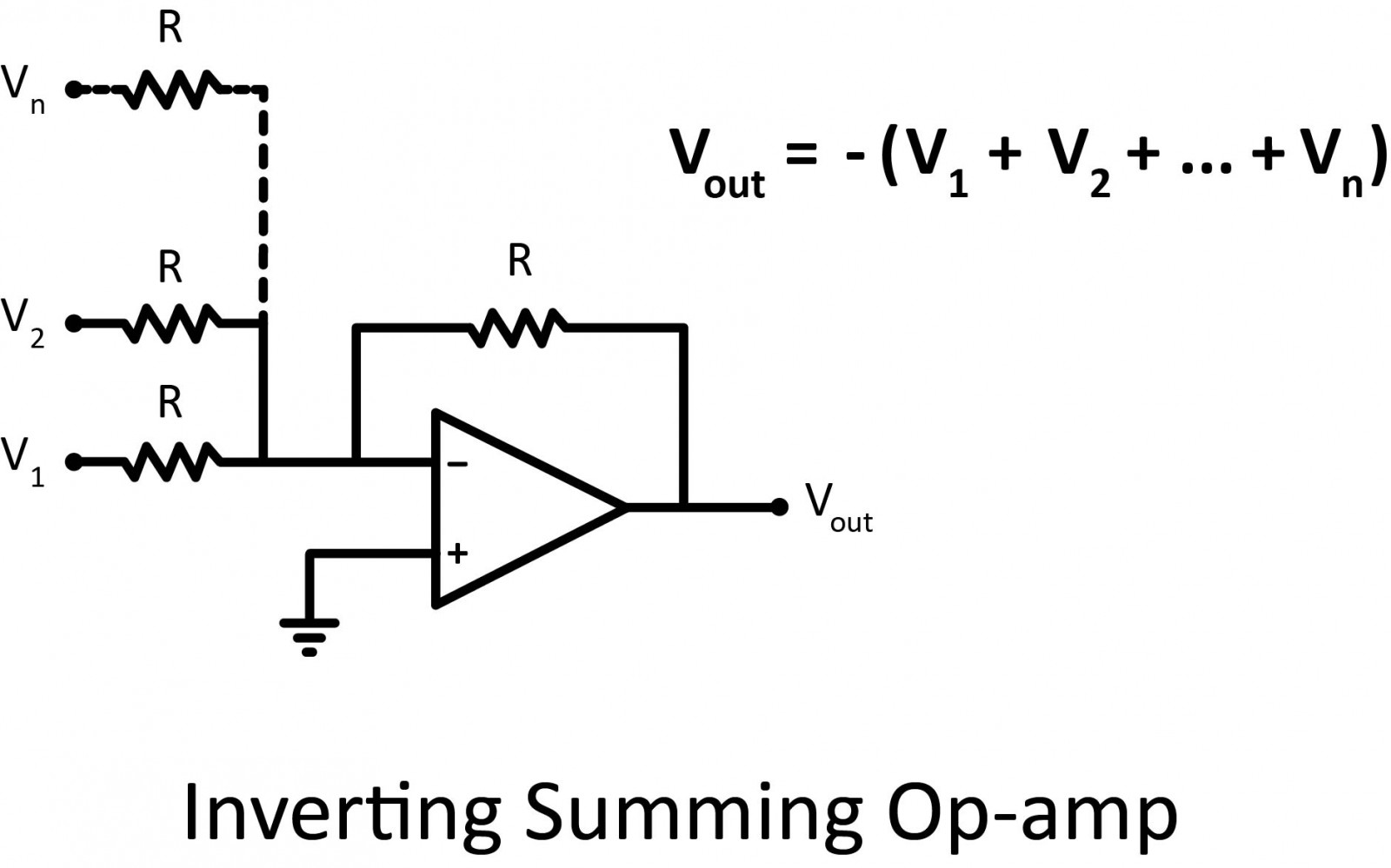
Inverting Summing Amplifier
By adding resistors in parallel on the inverting input pin of the inverting operational amplifier circuit, all the voltages are summed.
Unlike the non-inverting summing amplifier, any number of voltages can be added without changing resistor values.
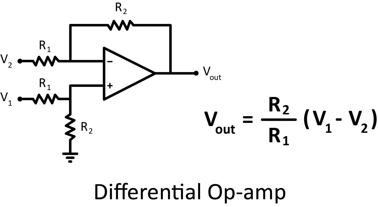
Differential Amplifier
The inverting operational amplifier amplified a voltage that was applied on the inverting pin, and the output voltage was out of phase. The non-inverting pin was connected to the ground in this configuration.
If the above circuit is modified by applying a voltage through a voltage divider on the non-inverting input, we end up with a differential amplifier as shown below amplifying the voltage difference between the two inputs.
An amplifier is useful not just because it lets you add, subtract, or compare voltages. Many circuits allow you to modify signals. Let’s see the most basic ones.
Integrator Op-amp
A square wave is very easy to generate, by just toggling an IO pin of a microcontroller for example. If a circuit needs a triangle waveform, a good way to do it is just by integrating the square wave signal. By placing a capacitor on the inverting feedback path, and a resistor on the inverting input pin as shown below, the input signal will be integrated.
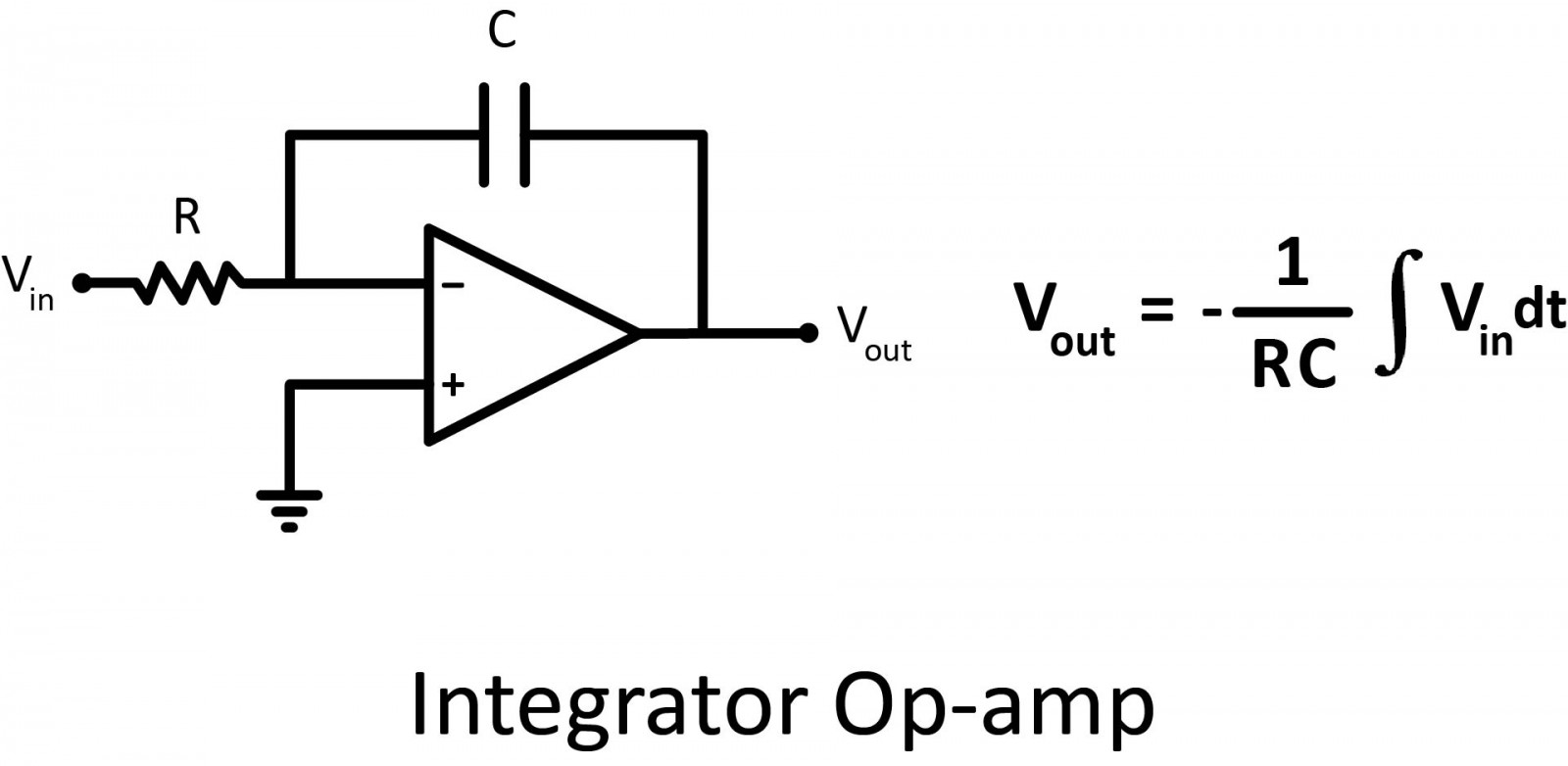
Note that a resistor is sometimes connected in parallel to the capacitor to avoid saturation issues. Because if the input signal was a very low-frequency sine wave, the capacitor would act like an open circuit and would block the feedback voltage. The amplifier would then act like a normal open-loop amplifier that has a very high open-loop gain, and the amplifier would be saturated. Thanks to a resistor in parallel to the capacitor, the circuit behaves like an inverting amplifier with a low frequency, and saturation is avoided.
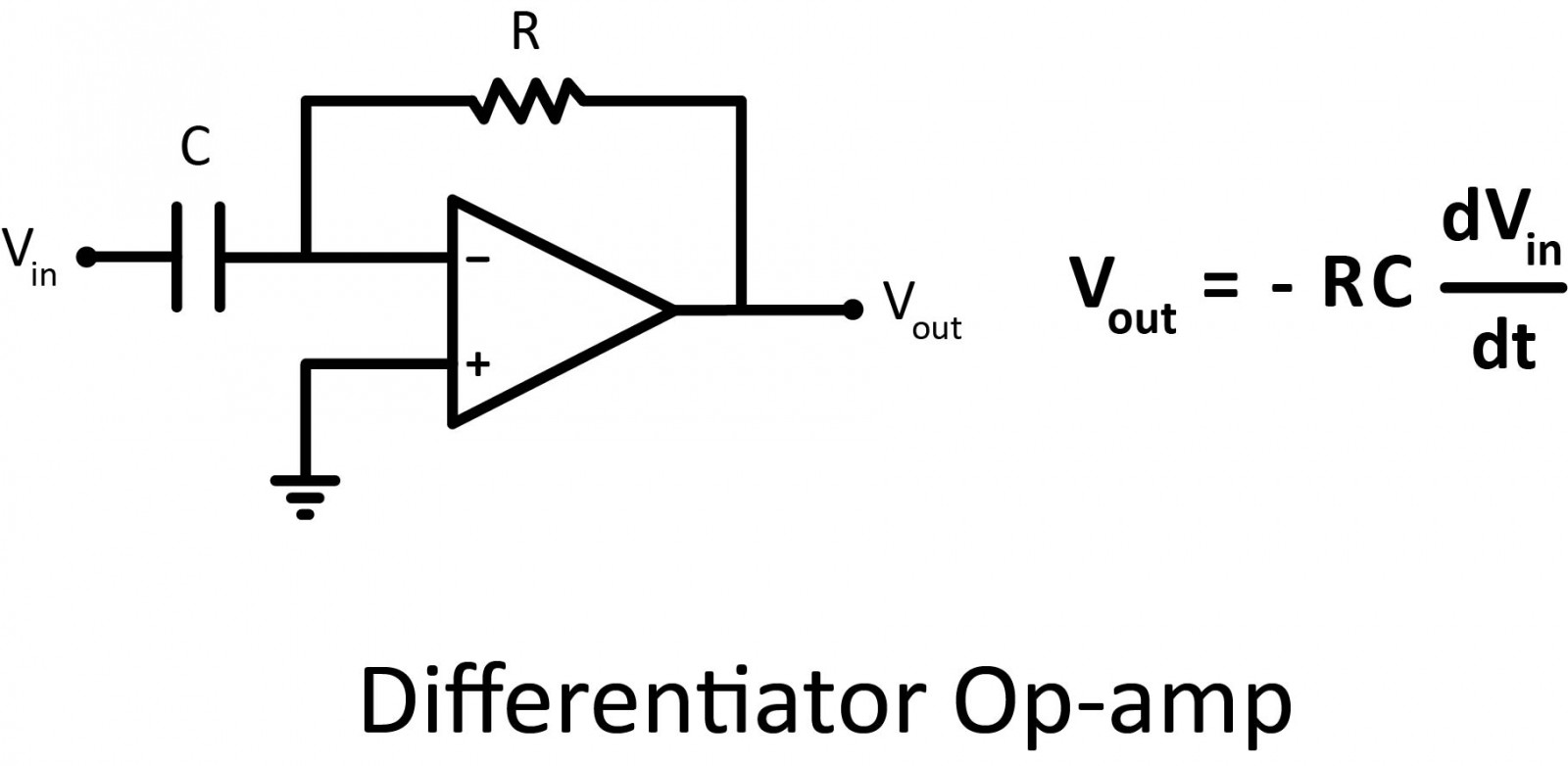
Differentiator Op Amp
The differentiator works similarly to the integrator by swapping the capacitor and the resistor.
There you have it, everything you might need to know about operational amplifiers as an electronics design beginner! This IC is the component of choice when you need a high-performance amplifier that provides high gain, high input impedance, and low output impedance. And by being able to swap out the various feedback components like resistors, capacitors, and inductors, you can fit together a ton of different variations to produce your own circuit. I’ll leave you with this great 3D illustration video of the op-amp.


