


Starting up
The resistor acts like a dam in a river in the sense that it slows the “flow” of electricity in a circuit. You can determine the value of through-hole resistors in Ohms (Ω) with their color codes or with numerical values in the case of surface mount resistors. 1 volt applied to a 1Ω resistor will limit the current to 1 amp. A resistor's value is directly proportional to the quantity of electricity it "blocks". A 1Ω will let 2 times more electricity pass than a 2Ω resistor. When designing circuit boards the resistor can be defined by these 2 symbols:
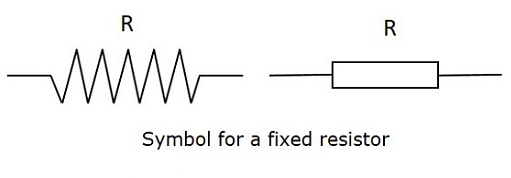
Source: ResistorGuide
"R", in this case, would be replaced by the value of the resistor. Because it can be hard to read big values like 3000000000 (3 billion), we add prefixes to the ohm symbol to represent thousand, million, billion, etc... 3 billion ohms would become 3 giga ohm or 3GΩ. Here are the prefixes for the most common values:
- Giga = 10^9 = G
- Mega = 10^6 = M
- Kilo = 10^3 = k
- Mili = 10^-3 = m
- micro = 10^-6 = μ
- nano = 10^-9 = n
The Ohm law specifies that the voltage across a resistor is equal to the current going through it multiplied by the value of the resistor
(Voltage = Resistance x Current or V=R*I)
When you connect resistors to each other, they are in series. They share the same current and will have the same voltage across them if they share the same value.
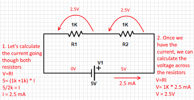
If we were to probe both ends of one of the resistors in the example above with a voltmeter, it would display 2.5V. This means that the resistor slows the electrons enough to reduce the potential energy by 2.5V. In this case, I would refer to "voltage" as the electric potential difference.
If you don't care about knowing how much voltage goes through each resistor, it is possible to take a shortcut. Two 1kΩ resistors are equivalent to one 2kΩ resistor. The formula is as follows:
Rtotal = R1+R2+R3+....Rn
Where Rn is the resistor at a given position.
In the example above, you could fill the formula with just one 2kΩ resistor.
Power is always given in watts and can also be affixed by one of the metric prefixes (ie. Gigawatt). To calculate power, the equation is:
Power = Voltage * current (P = VI). In the case of the example above, each resistor dissipates 2.5V * 2.5 mA= 6.25 mW of power. Power, just like the voltage across each resistor, can be added together to know the full power dissipation of the circuit. In this case, the circuit would diffuse 6.25 mW + 6.25 mW = 12.5 mW of power as heat.
Because a resistor produces heat when current flows through it, be careful not to overload each resistor as you might get mighty burns! Most of them are only rated at 250 mW, about half of what a PC USB port can output.
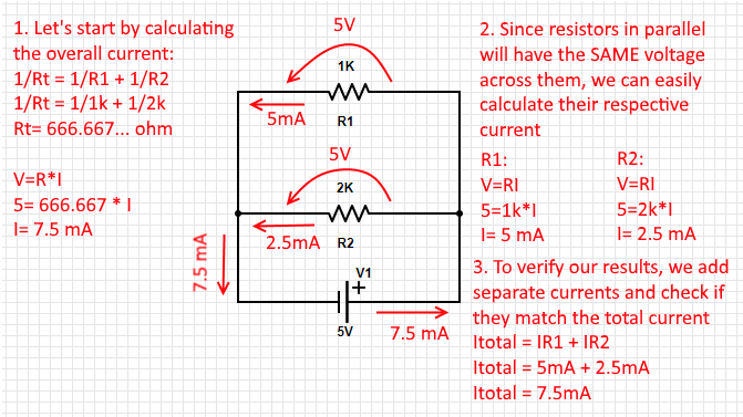
Resistors in parallel are a bit more complex because their current split depends on their value in ohm. You can easily calculate the current in each branch by treating them as if they were in series and then adding each of their current to make up the total value. If you wish to treat resistors as if they were only one, the formula is as follows: 1/Rtotal = 1/R1 + 1/R2 +... 1/RN. You then have to isolate Rtotal and use it in V=R*I Here is an example:
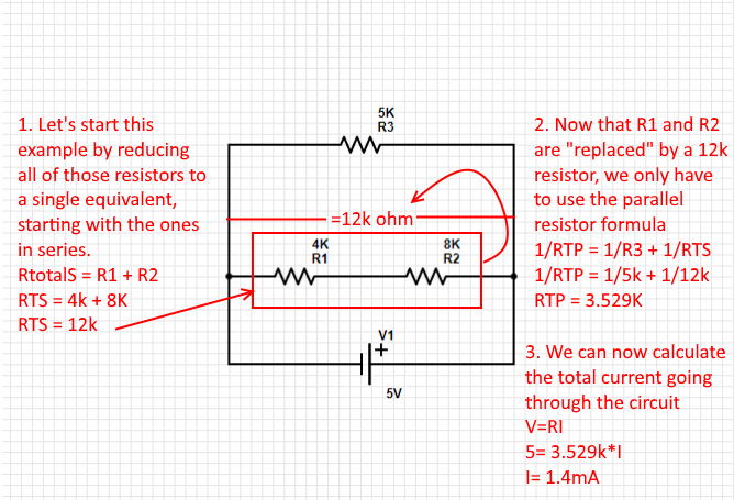
When you are faced with resistors both in parallel and in series in the same circuit, you need to start off with the ones in series in the same branch. Then, you can use the formula below to reduce resistors in parallel to a single one.
1/RTotal = 1/R1 + 1/R2 +.... 1/Rn.
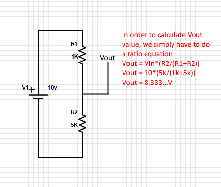
A quick way of converting a large voltage into a smaller one is by using a voltage divider comprised of 2 resistors in series. You can easily determine the value of the resistor needed with a quick ratio formula. A divider circuit made of two resistors of the same value will always cut the voltage in half between them. The formula used will be: Vout = Vin * (R2/(R1+R2))
Here is a quick example:
Through Hole
The most found resistor in older electronics or audio equipment. They are more reliable than their SMD (surface mount) counterparts and it is one of the reasons why they are still around. Building PCBs around those components is harder than with SMDs as you cannot solder them on both sides at the same time and it requires drilling, which increases the production costs.
Source: Electronics-tutorials.ws
The tolerance tells by how much a resistor can vary. A 100kΩ resistor with a 1% tolerance can have a value between 99kΩ and 101kΩ ohm.
SMD resistor
SMD or Surface Mounted Device resistors were invented to make the manufacturing process faster, as you can simply apply solder paste to a PCB, put the components on their respective pads, and shove everything in a reflow oven to solder every component at once. The way of telling an SMD resistor value is either with a 3-digit code, a 4-digit code, or with EIA-96 code.
Digit Code
3 or 4 digit codes are composed of number or number + R where R represents a decimal point. In a 3 digit code, the first 2 numbers are the value and the last one is a power of ten. For example, 365 would mean 36 x 10^5 ohm or 100kΩ.
The same thing applies to a 4 digit codes, but gives a higher number of significant figures.
Let's say you need a very precise 0.38 ohm resistor, a 4-digit code would allow expressing that value with "0R38".
EIA-96 code
This code is also comprised of 3 digits, two numbers for the significant figures, and a letter for the multiplicator. Here is a nice cheat sheet I've found which explains what each code represents. You'll notice that it is not possible to write each value with the EIA-96 as there are "steps" in the way significant figures are represented.
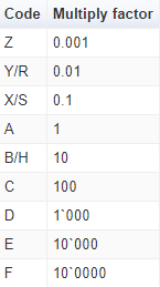
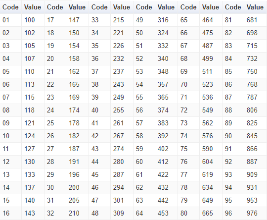
Source: Resistor Guide
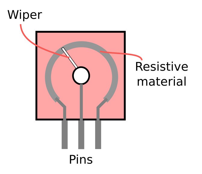
Potentiometer
A potentiometer is essentially a variable resistor. It is comprised of a knob or a slider that moves a wiper on a resistive track to act like an adjustable tension divider. If you were to probe either side pins with an Ohm-meter on the schematic below and compare one of them with the middle pin, you would read a changing value when you turn the knob around.
Source: BuildElectronicCircuits
Potentiometers may come in various shapes and styles but the most common would be rotatory and linear.
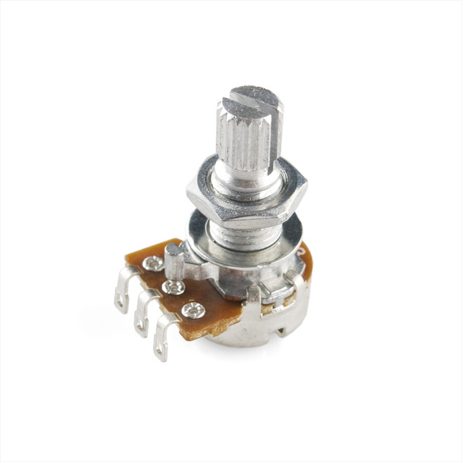
Rotary Potentiometer from Robotshop
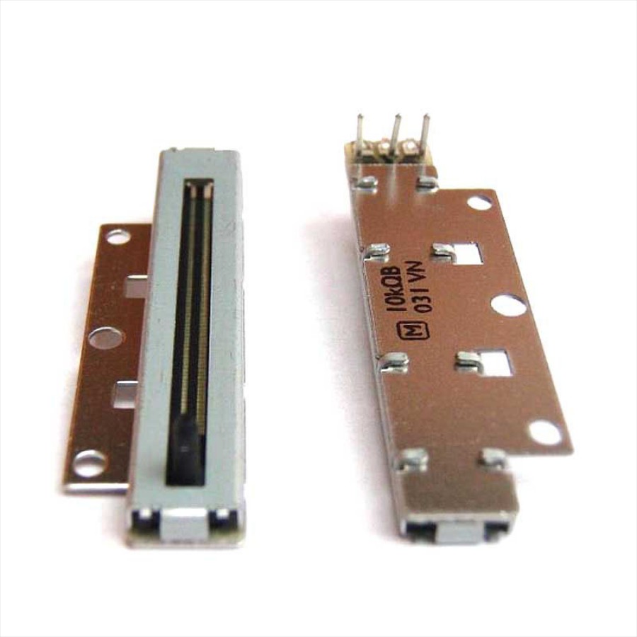
Linear Potentiometer from Robotshop
This ends the first edition of Electronics Done Quick, do not hesitate to comment or offer suggestions.
I've used PartSim simulator to build the circuits above and Paint.net for image editing.