When you string a bunch of transistors together, then you get what’s called a logic gate, which lets you manipulate binary numbers in any way imaginable. Most logic gates have two or more inputs and one output.
Input: All logic gates require some kind of input values so that they have numbers to compare. High or low binary conditions are represented by different voltage levels. In most logic gates, the low state is approximately zero volts (0 V), while the high state is approximately five volts (5 V).
Output: Once a logic gate has a chance to process your input, it can then make a decision on whether to open its gate or keep it closed. This output is entirely determined by the type of logic gate you’re using, and some will only open if you have two high voltages as an input, whereas others will only open if you have two low voltages as inputs.
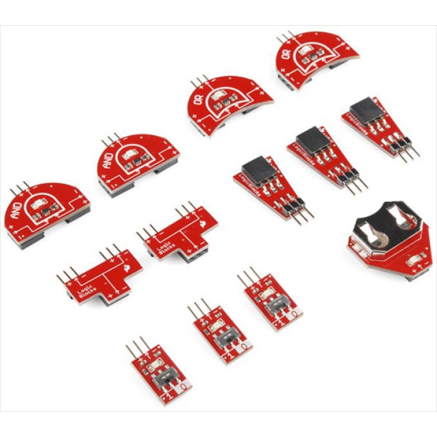
By using combinations of logic gates, complex operations can be performed and more advanced logic circuits can be built such as multiplexers, registers, arithmetic logic units (ALUs), and computer memory, all the way up to complete microprocessors, which may contain more than 100 million gates. In modern practice, most gates are made from field-effect transistors (FETs), particularly metal–oxide–semiconductor field-effect transistors (MOSFETs).
In theory, there is no limit to the number of gates that can be arrayed together in a single device. But in practice, there is a limit to the number of gates that can be packed into a given physical space. Arrays of logic gates are found in digital ICs. As IC technology advances, the required physical volume for each individual logic gate decreases and digital devices of the same or smaller size become capable of performing ever-more-complicated operations at ever-increasing speeds.
Logic Circuit Diagram
A logic circuit diagram uses the graphical representation or description of logic gates to represent a logic expression. An example of a logic circuit diagram shows below with three inputs (A, B, and C) and one output (Y).

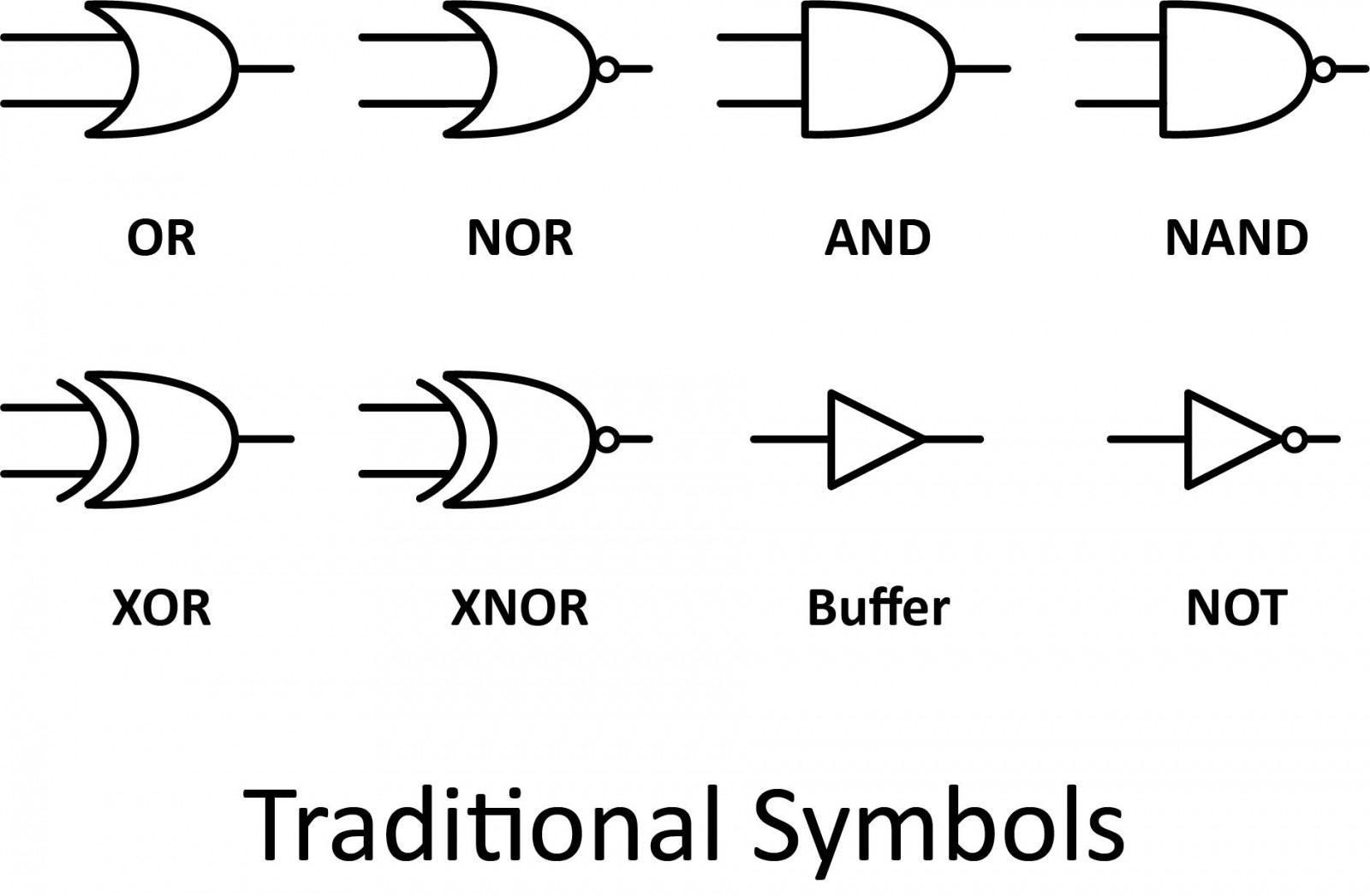
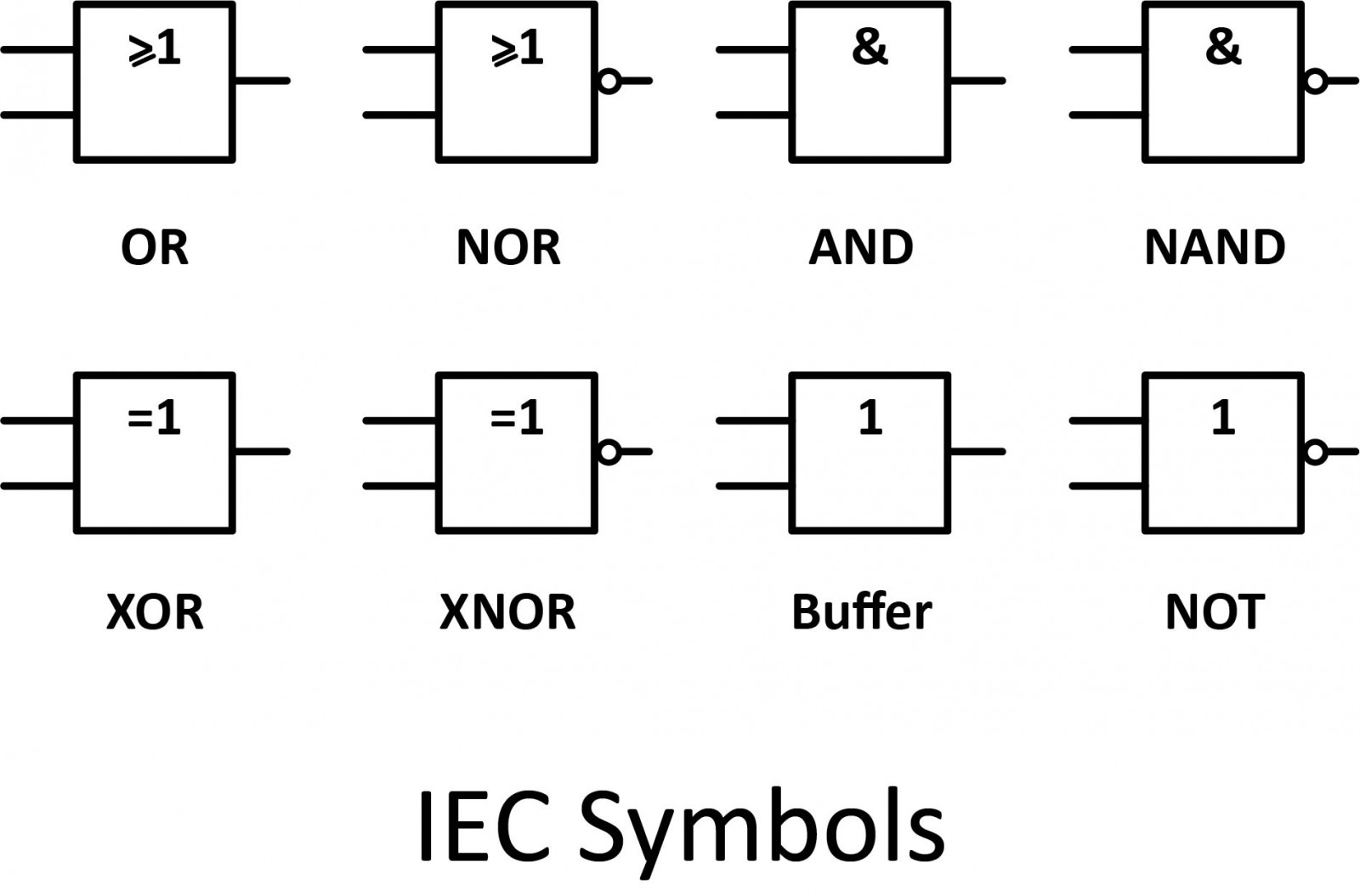
There are two series of symbols for logic gates. The traditional symbols have distinctive shapes making them easy to recognize, they are widely used in industry and education. The IEC (International Electrotechnical Commission) symbols are rectangles with a symbol inside to show the gate function. They are rarely used despite their official status.
Truth Table
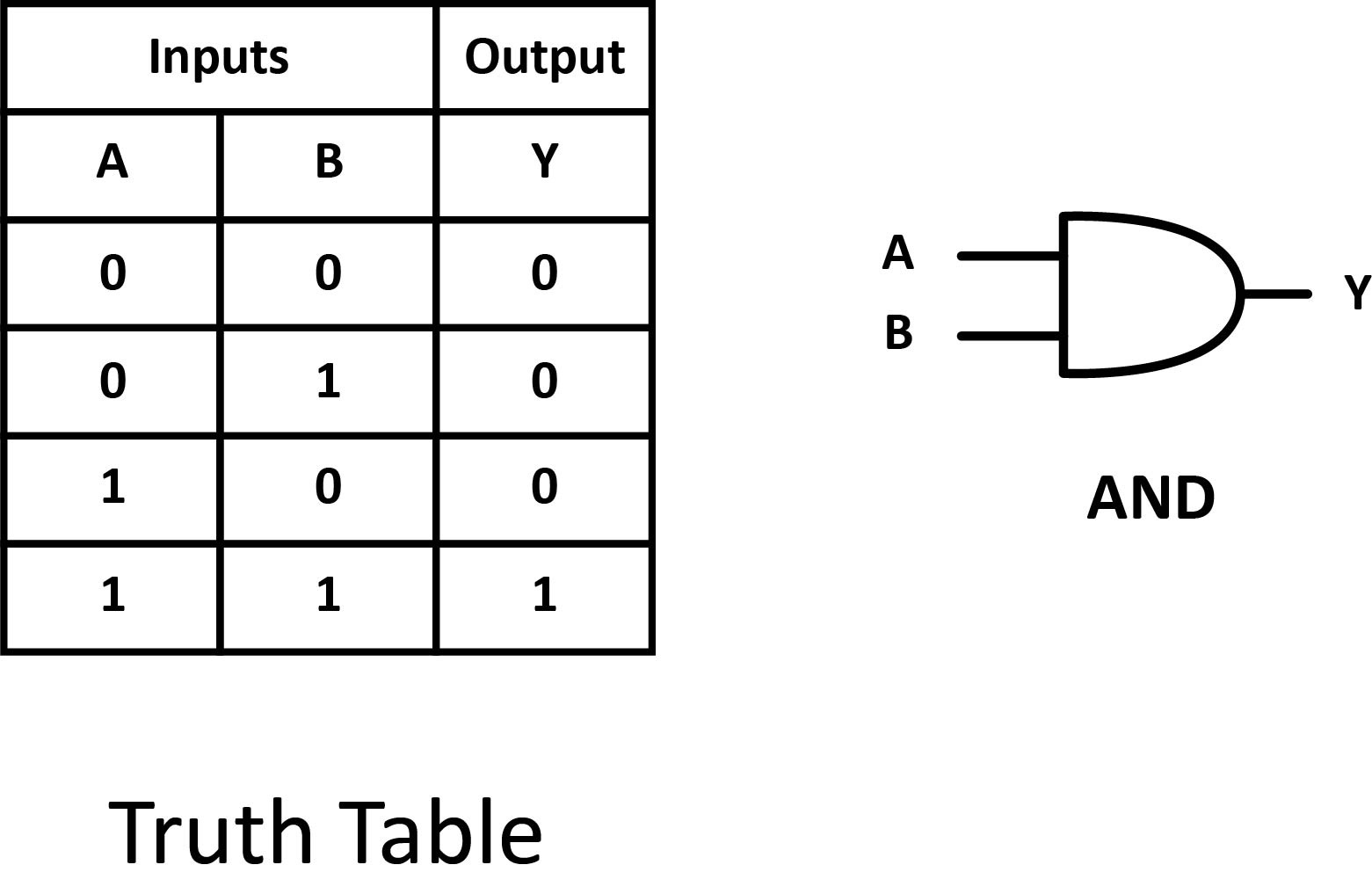
Logic gates implement Boolean logic, which can be represented through a truth table. A truth table is a tabular representation of the inputs and the output of a logical operation. On the left-hand side, all the possible combinations of the inputs are written and on the right-hand side, the output of the Boolean operation performed on the given inputs is written. Here is the truth table of the AND gate.
Boolean Expression
Boolean algebra can be used to write a logic expression in the form of an equation. There are symbols and operators that are used to express the output of a logic circuit.

AND
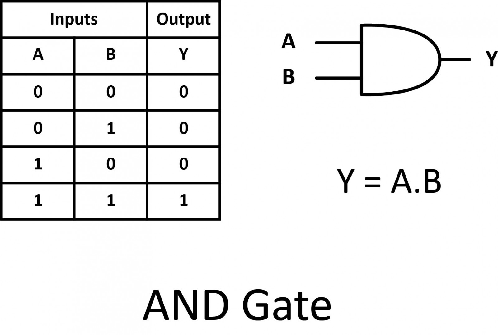
One of the easiest gates to understand is the AND gate, so-called because the output of this gate will be "true" if and only if all inputs (first input and the second input) are "true". Otherwise, the output is "false".
A dot (.) is used to show the AND operation (A.B). Bear in mind that this dot is sometimes omitted (AB). The following illustration shows the circuit symbol, truth table, and Boolean expression.
In case you might have been wondering, AND gates can have more than two inputs.
OR
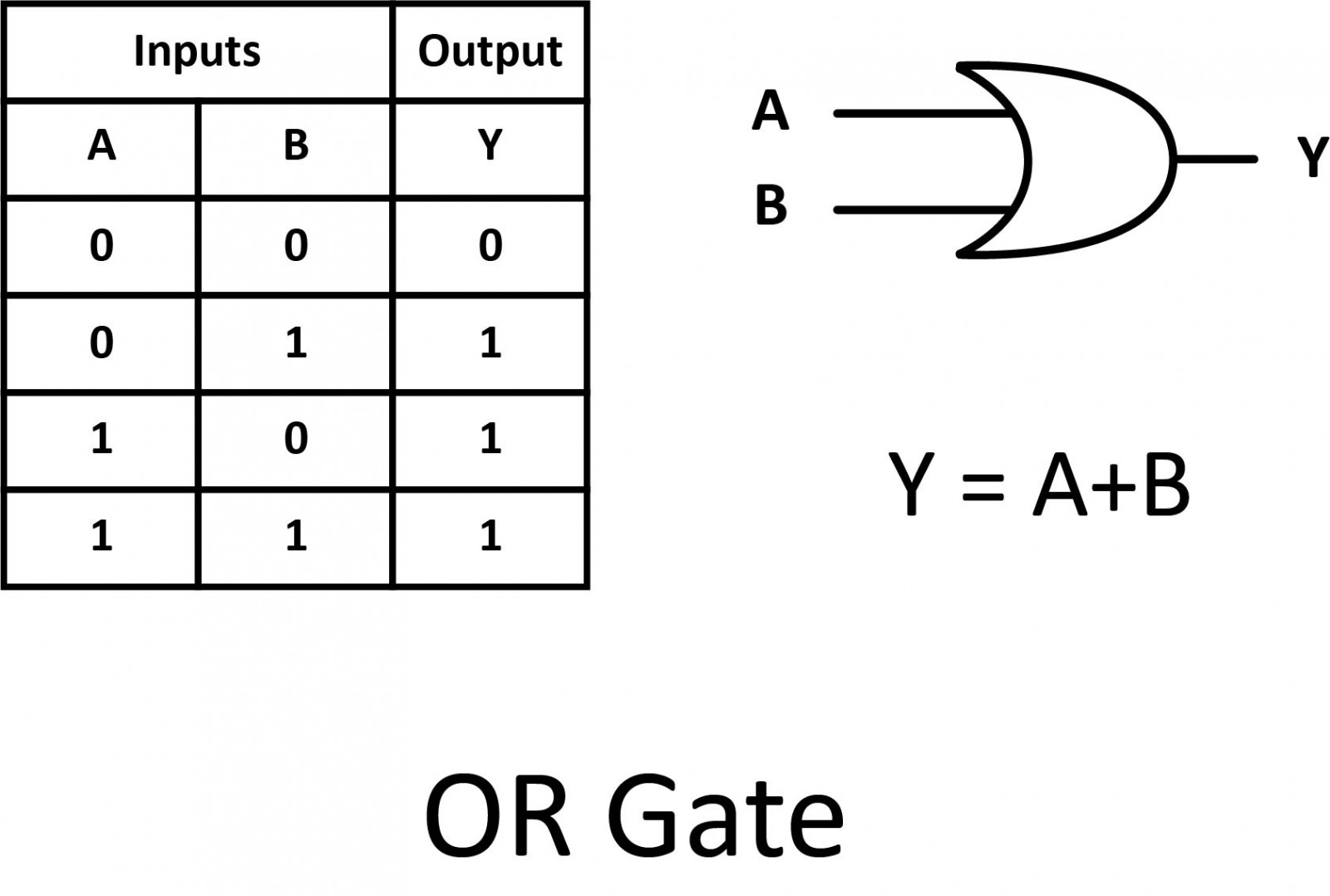
Our next gate to investigate is the OR gate, so-called because the output of this gate will be "true" if either or both of the inputs are "true". If both inputs are "false", then the output is "false". A plus (+) sign is used to show the OR operation.
NOT
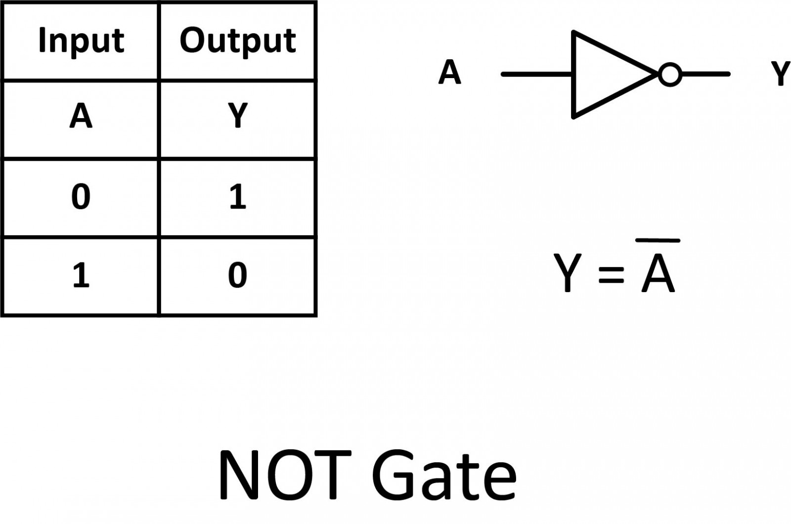
A logical inverter, sometimes called a NOT gate to differentiate it from other types of electronic inverter devices. It has only one input. It reverses the logic state. If the input is 1, then the output is 0. If the input is 0, then the output is 1. This is also shown as (A'), or A with a bar over the top, as shown below.
Buffer
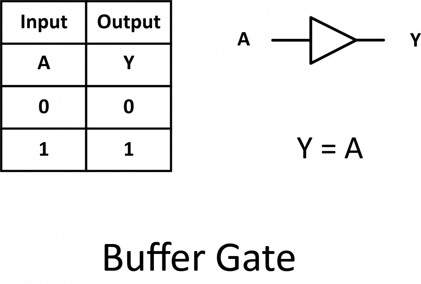
Sometimes in digital electronic circuits, we need to isolate logic gates from each other or have them drive or switch higher than normal loads (such as relays, solenoids, and lamps) without the need for inversion. One type of single-input logic gate, that allows us to do just that, is called the digital buffer.
NAND
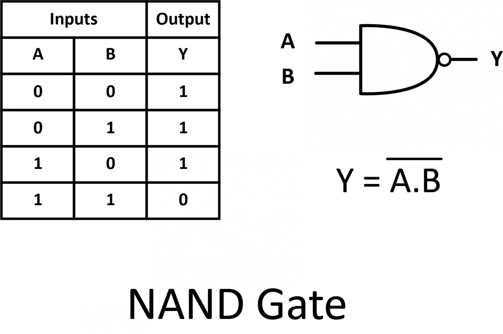
A variation on the idea of the AND gate is called the NAND gate. The word “NAND” is a verbal contraction of the words NOT and AND. The output is "true" if any of the inputs are "false".
The symbol is an AND gate with a small circle on the output to illustrate this output signal inversion. This is also shown as (A.B) with a bar over the top. The truth table for a NAND gate is, as one might expect, exactly the opposite of that of an AND gate.
NOR
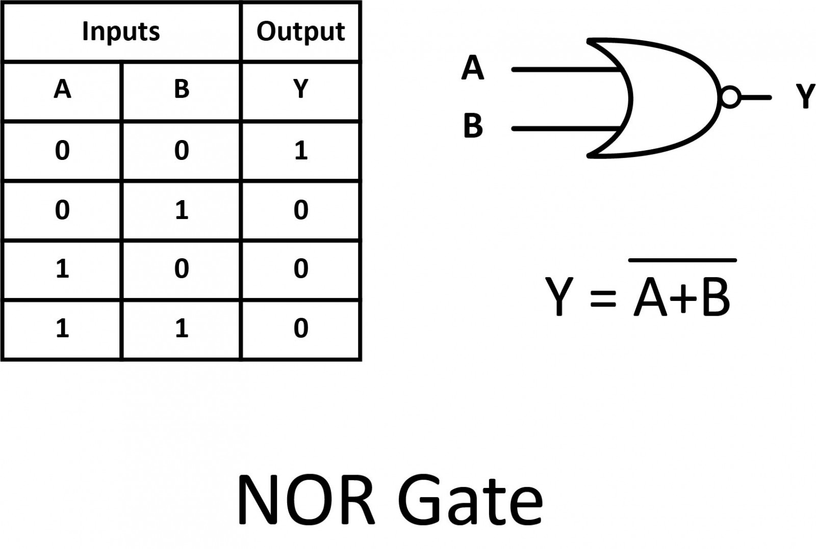
As you might have suspected, the NOR gate is an OR gate with its output inverted. Its output is "true" if both inputs are "false". Otherwise, the output is "false".
The symbol is an OR gate with a small circle on the output. The small circle represents inversion. This is also shown as (A+B) with a bar over the top.
XOR
The previous gates are all fairly direct variations on three basic functions: AND, OR, and NOT. The XOR gate, however, is something quite different.
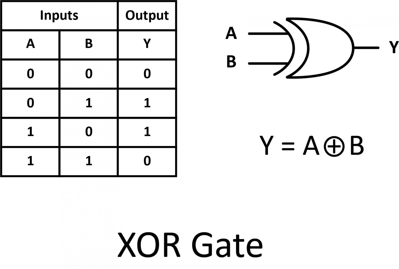
The XOR (Exclusive-OR) gate’s output is "true" if either, but not both, of the inputs are "true". The output is "false" if both inputs are "false" or if both inputs are "true". Another way of looking at this circuit is to observe that the output is "true" if the inputs are different, and "false" if the inputs are the same.
An encircled plus sign (⊕) is used to show the XOR operation.
XNOR
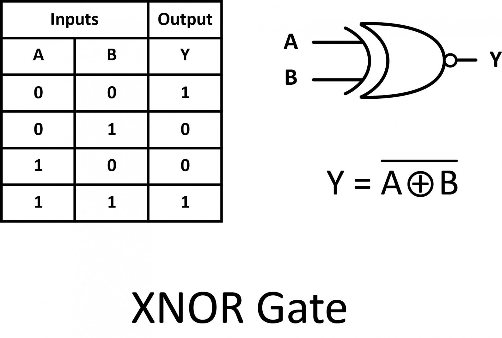
Finally, our last gate is the Exclusive-NOR gate, otherwise known as the XNOR gate.
The XNOR gate is a combination of an XOR gate followed by a NOT gate. Its output is "true" if the inputs are the same, and "false" if the inputs are different.
The symbol is an XOR gate with a small circle on the output that represents the inversion. This is also shown as (A⊕B) with a bar over the top.
Summary
- AND: Output is “true” only if all inputs are “true”.
- OR: Output is “true” if either or both inputs are “true”.
- NOT: Output is inverted.
- Buffer: Output is the same.
- NAND: Output is “true” if either or both inputs are “false”.
- NOR: Output is “true” only if all inputs are “false”.
- XOR: Output is “true” if inputs are different.
- XNOR: Output is “true” if inputs are the same.

A set of rules or laws of Boolean Algebra expressions have been invented to help reduce the number of logic gates needed to perform a particular logic operation. The simplified equations may be translated back into circuit form for a logic circuit performing the same function with fewer components. If an equivalent function may be achieved with fewer components, the result will be increased reliability and decreased cost of manufacture.
Inverting all inputs to a gate reverses that gate’s essential function from AND to OR, and vice versa, and also inverts the output. So, an OR gate with all inputs inverted (a Negative-OR gate) behaves the same as a NAND gate, and an AND gate with all inputs inverted (a Negative-AND gate) behaves the same as a NOR gate. De Morgan’s laws state the same in “backward” form, that is, inverting the output of any gate results in the same function as the opposite type of gate (AND vs. OR) with inverted inputs.
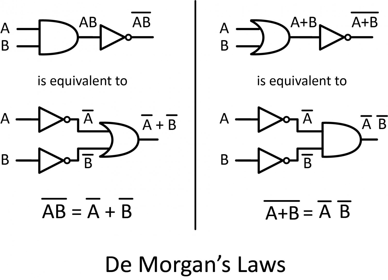
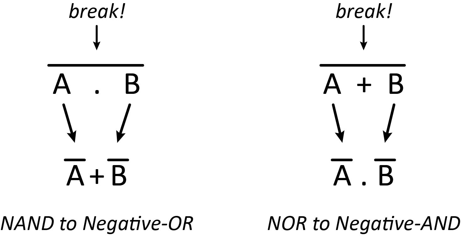
De Morgan’s theorem may be thought of in terms of breaking the long bar symbol. When the long bar is broken, the operation underneath the break changes from addition to multiplication, or vice versa, and the broken bar pieces remain over the individual variables.
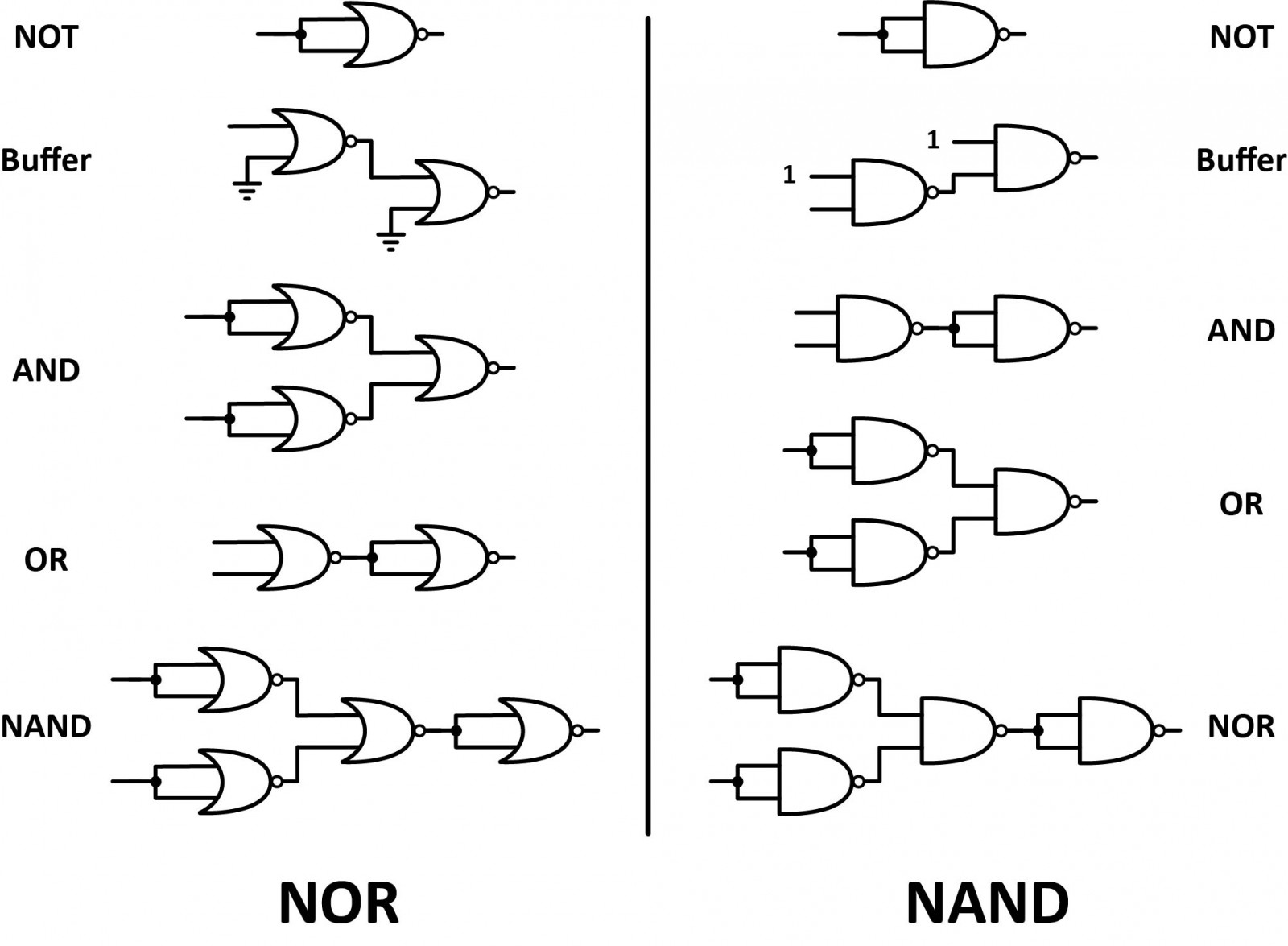
Both the NAND gate and the NOR gate can be classified as “universal” gates as they can be used to construct any other gate type.
Combinational Circuits
Combinational circuits are a collection of logic gates. Their outputs depend only on the current inputs. Combinational circuits are also time-independent. Along with the absence of concepts like past inputs, combinational circuits also do not require any clocks. The result of these properties is a simple circuit capable of implementing complex logic using only logic gates.

Sequential Circuits
Sequential circuits are a collection of memory elements. These circuits are capable of “remembering” data. Hence, a sequential circuit’s output depends on current and past inputs, as well as the clock. These circuits are quite complex. They are capable of implementing complex logic with memory. Add a memory element and feedback to a combinational circuit and you get a sequential circuit.
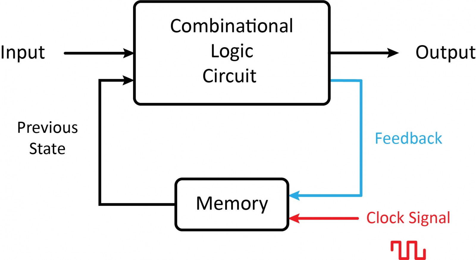
Combinational Logic Circuits
It's possible to do any calculation you can think of by combining a different pattern of logic gates. The gates compare and combine two series of binary numbers, corresponding to the decimal numbers in your calculation, and produce a new series of binary numbers equal to the result. The addition is carried out by circuits called half-adders and full adders (which can carry on the results of a previous addition). Subtractors work in a very similar way. Multipliers use a collection of AND gates to multiply two numbers with a series of additions. Here are some of the most common combinational logic circuits.
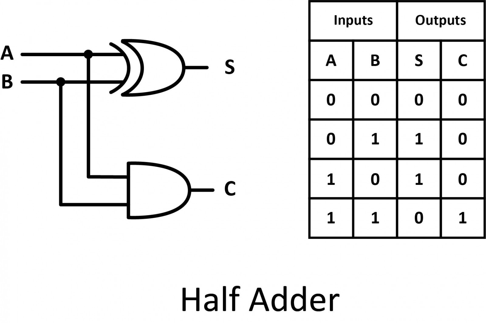
Half Adder
Half adder is a combinational logic circuit with two inputs and two outputs. The half-adder circuit is designed to add two single-bit binary numbers A and B. It is the basic building block for the addition of two single-bit numbers. This circuit has two outputs sum and carry.
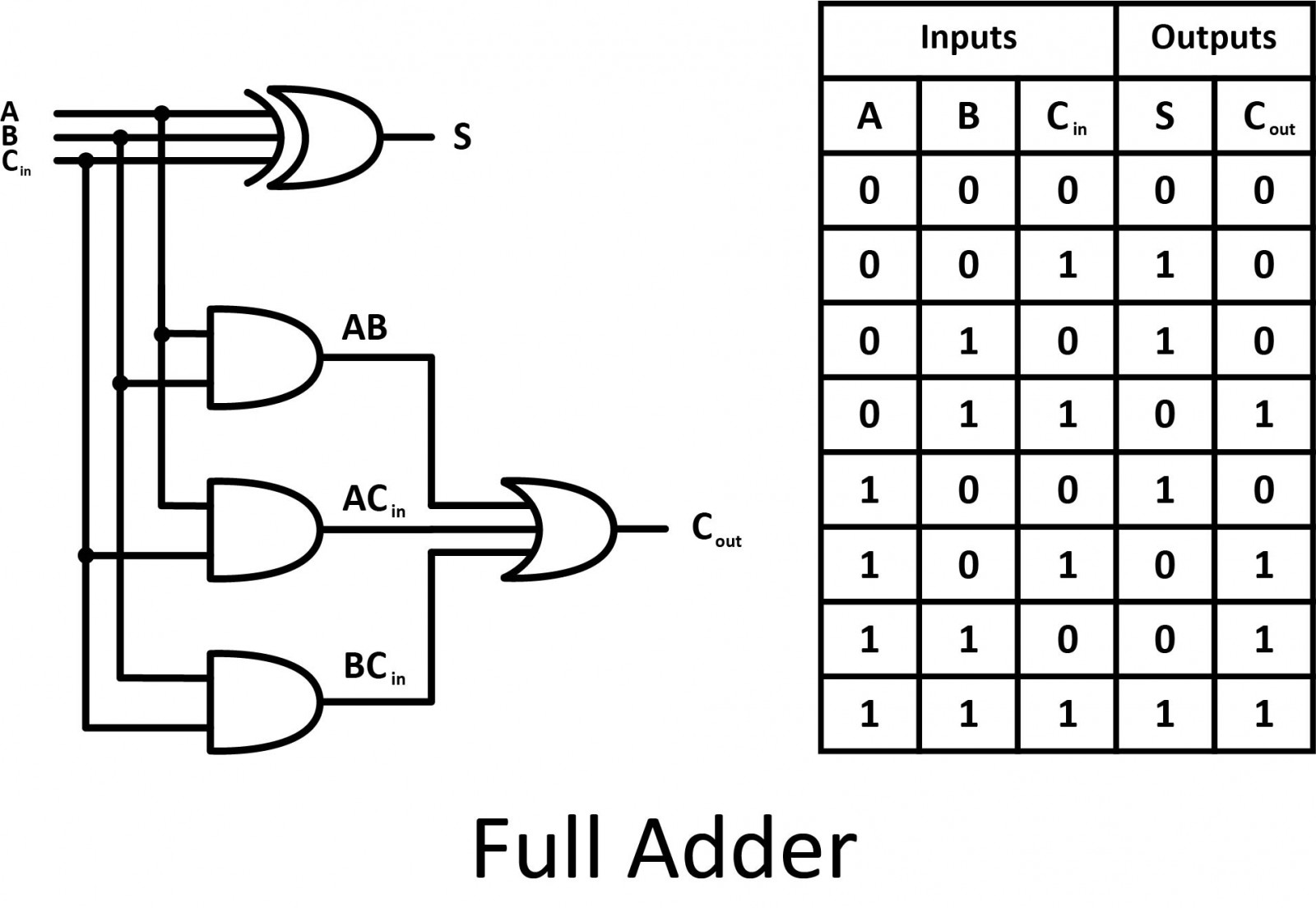
Full Adder
A full adder is developed to overcome the drawback of a half adder circuit. It can add two one-bit numbers (A and B), and carry C. The full adder is a three-input and two-output combinational circuit.
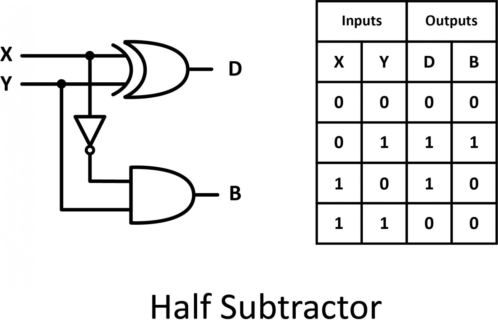
Half Subtractor
Half subtractor is a combinational circuit with two inputs and two outputs (difference and borrow). It produces the difference between the two binary bits at the input and also produces an output (Borrow) to indicate if a 1 has been borrowed.
Full Subtractor
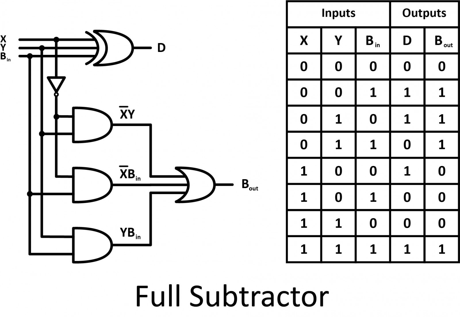
The disadvantage of a half subtractor is overcome by the full subtractor. The full subtractor is a combinational circuit with three inputs and two outputs. X and Y are the two bits to be subtracted, (B in) is the borrow produced by the previous stage, D is the difference, and (B out) is the borrow output.
Comparator
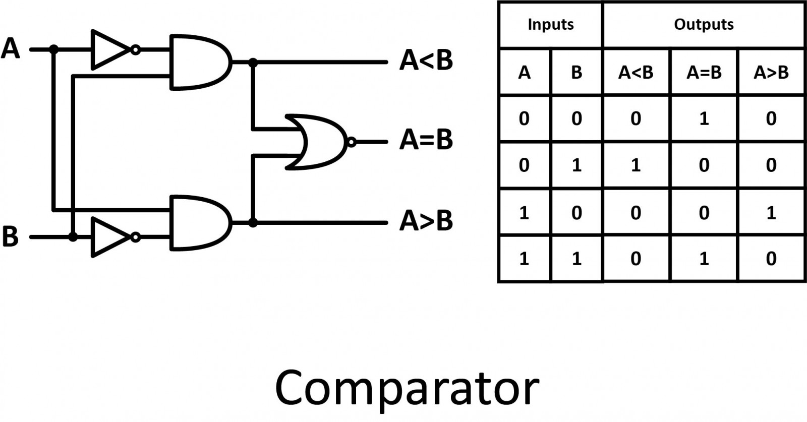
Comparators compare the digital signals present at their input terminals and determine whether the value of the first input is greater than, smaller than, or equal to the value of the second input.
Multiplexer
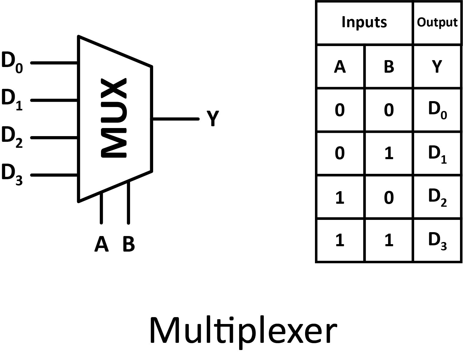
Multiplexers have several data input signals (D0 to D3), as well as a control input (A and B). The output (Y) is identical to one of the inputs. The value of the control signal determines which input to take into account.
Demultiplexer
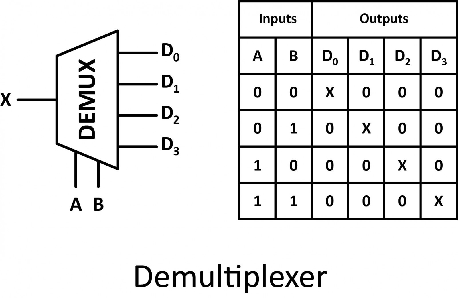
Demultiplexers have one data input signal (X), control inputs (A and B), and several output signals (D0 to D3). All of the output signals are false except for the one selected by the control input. The selected output is identical to the data input (X).
Sequential Logic Circuits
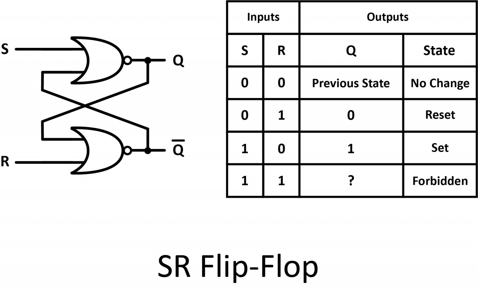
Flip-Flops
The basic building block of a sequential circuit is a flip-flop. The reason they are called flip-flops is that they flip between two stable states in the manner of a seesaw that comes to rest on one end or the other. It is a storage device capable of storing one bit of data. Flip flop has two inputs and two outputs labeled Q and Q’. Flip-flops are found in the shift register, counters, and memory devices.
Registers
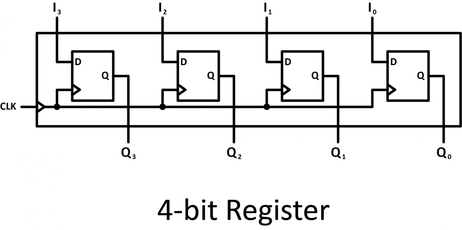
Registers are clocked in sequential circuits. A register is a collection of flip-flops. Each flip-flop is capable of storing one bit of information. An n-bit register consists of n flip-flops and is capable of storing n bits of information.
Counters
A counter is a device that stores the number of times a particular event or process has occurred, often in relationship to a clock signal. Generally, counters consist of a flip-flop arrangement which can be a synchronous counter or an asynchronous counter.

While individual logic gates on their surface are all relatively simple and straightforward, it’s the combination of these gates together that really brings out their superpowers. By using a combination of logic gates together in an integrated circuit, you can perform some incredibly complex calculations. And the more logic gates that you pack into the same physical space, the faster you can calculate! Wherever you look in the world of digital electronics, you’ve got logic gates at play, doing all of the heavy mathematical liftings to make some amazing things happen. I’ll leave you with a video about logic gates and how can they be constructed from simple transistors.


