


The invention of the transistor was the beginning of a technological revolution that is still growing. All of the complex electronic devices and systems around us today are the results of early developments of the transistor. Transistors got so small over time that now a modern microprocessor contains billions of them!
![]()
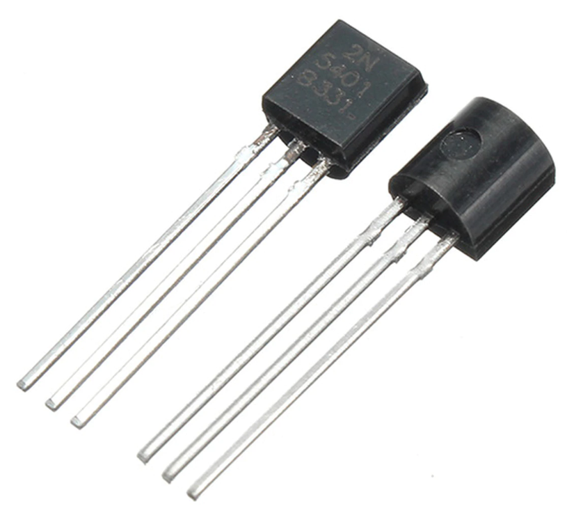
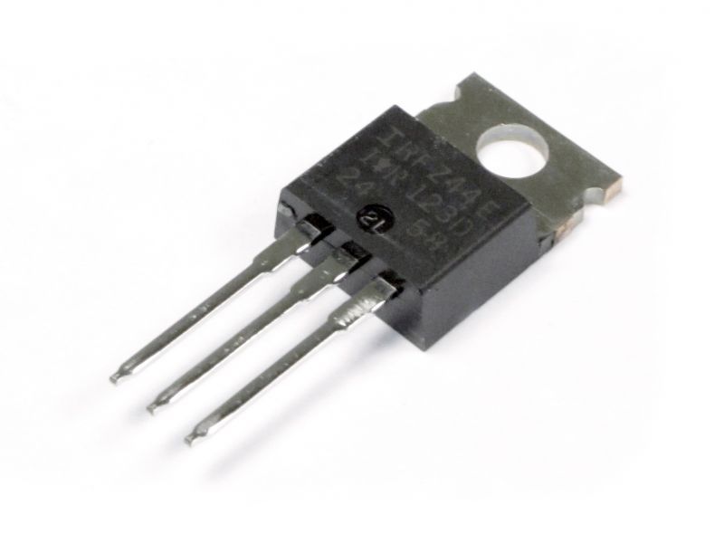
Source: IndiaMART
A transistor is simply what you would get if you stacked two diodes and tied their anodes together. You can know more about diodes here. It can be used either as a "switch" or an "amplifier". A group of transistors can be arranged together to form more complex digital electronics such as logic gates, digital memory, and microprocessors.
Transistor as a Switch
Unlike the mechanical switch, a transistor does not have moving parts and it also does not require a human to control the switch. Furthermore, it can be switched on and off much more quickly than the mechanical switch. Above all of that, it is incredibly tiny!
Transistor as an Amplifier
The transistor can also be used to amplify current. If you introduced a weak fluctuating signal, like what you would find in a microphone, at the input of a transistor, you will get an amplified signal at the loudspeaker.
There are different types of transistors. The most common types are the Bipolar Junction Transistor (BJT) and the Field Effect Transistor (FET). Here is the full list.
![]()
Transistors are three-terminal devices, on a Bipolar Junction Transistor, those pins are called collector (C), base (B), and emitter (E). There are two versions of the BJT transistor: NPN and PNP which describes the physical arrangement of the semiconductor materials from which they are made. This only changes the flow direction of the current. For now, let's focus on the more common NPN transistor.
The basic principle about transistors is that by providing a small current between the base and the emitter, you will allow a larger current to flow between the collector and the emitter.
![]()
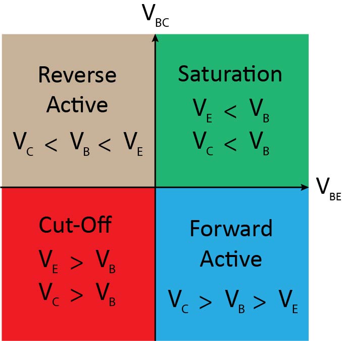
Source: Pixel Electric
Operation Modes
There are four distinct modes of operation in the transistor that depend on the voltages at its three terminals. The four modes are:
- Saturation – The transistor operates as a switch in the ON state.
- Cut-Off – The transistor operates as a switch in the OFF state.
- Active – The transistor operates as an amplifier.
- Reverse Active – The transistor operates as a less effective amplifier than the active mode and therefore will not be used.
In saturation and cut-off modes, the transistor will function as a switch. If the voltage between the base and the emitter exceeds a threshold voltage (around 0.7 V in most transistors), it will allow the current to flow between the collector and the emitter where the main circuit is. If it falls below that threshold voltage, the current will stop flowing and the transistor will be an OFF switch.
![]()
Active mode is the most powerful mode of the transistor because it turns the device into an amplifier. The current going into the base amplifies the current going between the collector and the emitter.
To operate in active mode, the base voltage must be less than the collector but greater than the emitter. That also means the collector must be greater than the emitter. The gain (amplification factor) of a transistor β linearly relates the collector current to the base current.

The actual value of β varies by the transistor. It is usually around 100, but can range from 50 to 2000, depending on which transistor you are using and how much current is running through it. If your transistor had a β of 100, for example, that would mean an input current of 1 mA into the base could produce 100 mA current through the collector.
![]()
BJT Applications
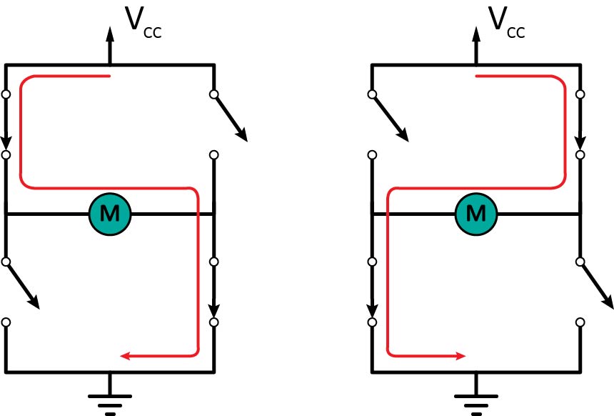
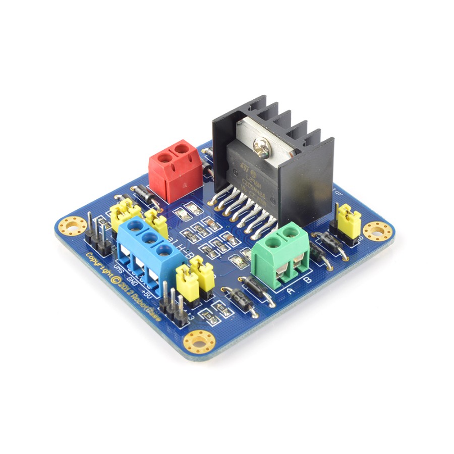
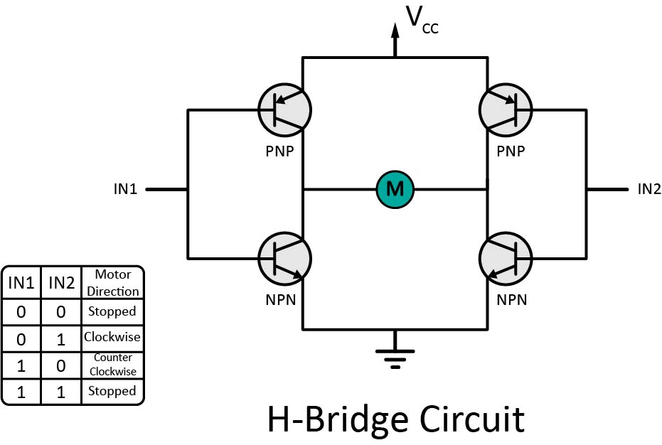
H-Bridge
An H-bridge is a simple circuit that lets you control the direction of a DC motor using transistors. A DC motor spins clockwise or counter-clockwise depending on the polarity of the voltage applied to the motor. The circuit consists of four transistors that act as switches, two PNP, and two NPN. By opening two switches and closing the other two, you can control the direction of the motor.
Source: RobotShop
You would normally control the transistors using a microcontroller such as an Arduino. The most important thing is to make sure all transistors can handle enough current for the motor, otherwise, it will burn out. For example, if the motor draws 1 Ampere of current, you need transistors that can handle a minimum of 1 Ampere.
Darlington Transistor
Darlington transistors are two BJTs connected together in such a way that the current amplified by the first transistor is further amplified by the second one. This configuration gives a much higher current gain than each transistor taken separately. A typical Darlington transistor has a current gain of 1000 or more, so only a small base current is needed to make the pair switch on higher switching currents.

![]()
Source: Wikipedia
A Darlington pair behaves like a single transistor, meaning it has one base, one collector, and one emitter. One drawback is an approximate doubling of the base-emitter voltage. Since there are two junctions between the base and emitter of the Darlington transistor, the equivalent base-emitter voltage is the sum of both base-emitter voltages
![]()
Darlington transistors can be used in high-current circuits, such as those involving computer control of motors or relays. The current is amplified from the normal low level of the computer output line to the amount needed by the connected device.
Phototransistor and Optocoupler
The phototransistor is a transistor that is able to sense light levels and alter the current flowing between the emitter and collector according to the level of light it receives.
The characteristics of the photo-transistor, under different light intensities, are very similar to the characteristics of a conventional bipolar transistor, but with the different levels of base current replaced by the different levels of light intensity.
There is a small amount of current that flows in the phototransistor even when no light is present. This is called the dark current and represents the small number of electrons that are injected into the emitter. Like the photo-generated electrons, this is also subject to amplification by the transistor.
![]()
![]()
Source: The Tech-FAQ
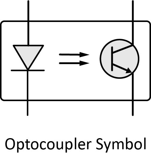
The phototransistor can be combined with an LED to form an optocoupler. An optocoupler is an electronic component that transfers electrical signals between two isolated circuits by using light. Optocouplers prevent high voltages from affecting the system receiving the signal.
Optocouplers are typically contained in a single package, often about the size of an integrated circuit.
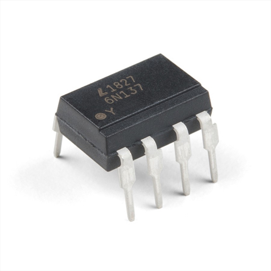
Source: RobotShop
If you’re designing an electronic device that will be susceptible to voltage surges, lightning strikes, power supply spikes, etc. then you’ll need one to protect low-voltage devices. An Optocoupler can effectively:
- Remove electrical noise from signals
- Isolate low-voltage devices from high-voltage circuits
- Allow you to use small digital signals to control larger AC voltages
A field-effect transistor (FET) consists of a channel of semiconductor material through which current can flow, with a different material controlling the conductivity of this channel. One end of the channel is known as the source, the other end of the channel is called the drain, and the control mechanism is called the gate. By applying a voltage to the gate, you control the flow of current from the source to the drain.
There are two types of field effect transistors, the N-channel FET and the P-channel FET.

Source: Solarbotics
FETs have become much more popular than bipolar transistors because of their use in integrated circuits (ICs), where thousands of transistors work together to perform a task. That’s because they’re low-power devices whose structure allows thousands of N- and P-channel FETs to be crammed into a single piece of silicon. When the FET acts as an OFF switch, the gate current is practically zero, whereas the base current of the BJT is always some value greater than zero.
The Field Effect Transistor has another major advantage over its standard bipolar transistor cousins, their input impedance is very high (thousands of Ohms) while the BJTs input impedance is comparatively low. This very high input impedance makes them very sensitive to input voltage signals, but the price of this high sensitivity also means that they can be easily damaged by static electricity.
There are two main types of field effect transistors, the Junction Field Effect Transistor (JFET) and the Metal Oxide Semiconductor Field Effect Transistor (MOSFET).
FET Applications
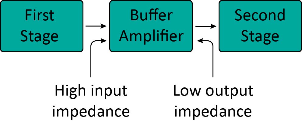
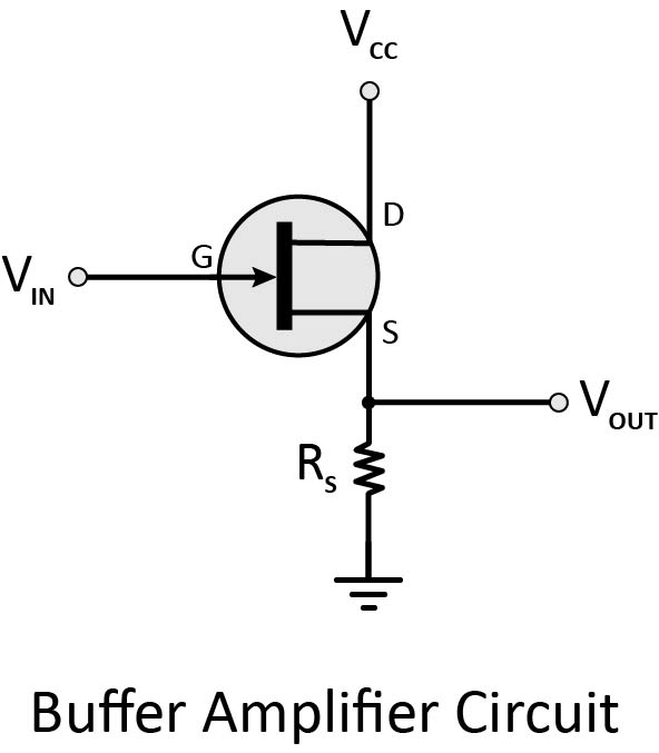
Buffer Amplifier
A digital buffer is an electronic circuit element that is used to isolate the input from the output, providing either no voltage or a voltage that is the same as the input voltage. Because of the high input impedance and low output impedance, a FET acts as an excellent buffer amplifier. That means that it draws very little current and will not disturb the original circuit. It is also called a unity gain buffer because it provides a gain of 1, which means it provides at most the same voltage as the input voltage, serving no amplification function..
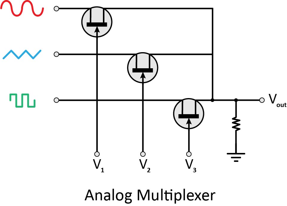
Multiplexer
An analog multiplexer, a circuit that steers one of the input signals to the output line, is shown in the figure. When the control signals (V1, V2, and V3) are more negative than the voltage applied between the gate and source terminals, then the FET operates in its cut-off region. By making any control voltage equal to zero, one of the inputs can be transmitted to the output. For instance, when V1 is zero, the signal obtained at the output will be sinusoidal. Similarly, when V2 is zero, the signal obtained at the output will be triangular and when V3 is zero, the output signal will be square-wave one. Normally, only one of the control signals is zero.
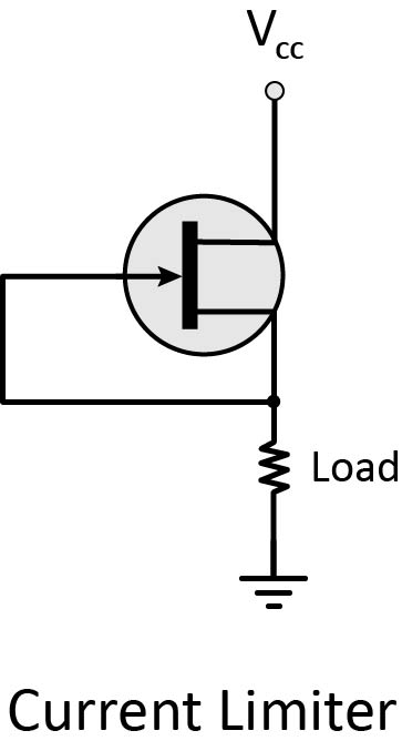
Current Limiter
JFETs can also be used to limit current. When the load current tries to increase to an excessive level (may be due to short-circuit or any other reason), the excessive load current forces the JFET into the active region, where it limits the current. A manufacturer can tie the gate to the source and package the JFET as a two-terminal device as shown.
In 1975, Gordon Moore proposed that the number of transistors on a silicon chip would double every two years as it is now known as Moore's Law.
Starting from 2010, however, Moore's Law began to break down and many today are asking if our age of unprecedented growth is coming to an end.
Electrical leakage is the main factor contributing to the slowing rate of growth. As transistors got smaller, as small as 10 nanometers, the channel that carries the electrical current through the transistor cannot always contain it. This generates heat which can wear out the transistors more quickly, making them even more susceptible to leakage.

Source: TechRepublic
Transistors are altering the landscape of technology. Computers once weighed 30 tons and now you can wear one around your wrist.
Transistor materials are changing too. Thanks to recent advances in research, transistors can now be made of materials like graphene, benzene molecules, or even DNA! This could lead to computer processors that are thousands of times faster than silicon-based products.
No matter where development goes, it is certain that computers will become faster, cheaper, and much smaller. Here is a video about 7 promising technologies that could replace the semiconductor transistor we have today.