


3x08M
Update: (this was all done a few months ago) Removed the servo that moved the eyes. Eyes are now fixed. Added an infrared receiver. Still toying with the program, but that goes very slowly with three processors, squeezing in the jumpercable that connects to the programming cable. I keep forgetting to connect it right so lots of times I end up uploading the program to the wrong chip. So many processors, so little time....
Update: Fixed the speed control / dual PWM problems. If all else fails in this project, at least I made a dual channel PWM with a picaxe 08M. It uses 255 bytes of the 256 bytes that are available in this tiny picaxe. How's that for getting the most out of a 08M?! See this tip/walkthrough for the details and video. Next up is that blasted object tracker. It really is a lot of extra work to debug a multi-proc board.
Update: problem with both sensors showing almost identical values solved. One of the signal wires to the sensors was loose leaving the input floating (bad very bad). I'd better get some thinner wires because the current ones are too thick and stiff. Started on programming the object tracker.
Update: Mounted the bumperskirts and they work reasonably well (inserted the picture at the bottom of the post). I'll probably have to make them stick out more to work better. Tried a few ways to mount the IR sensors to the servo. Ran into trouble there. The servo is on a different plate than the sensors and with the tight space inside the robot it is allmost impossible to get anything assembled or mounted.
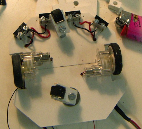
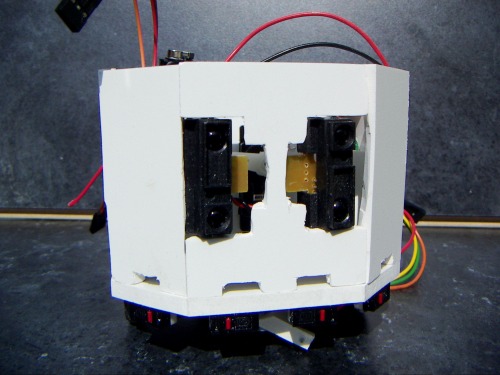
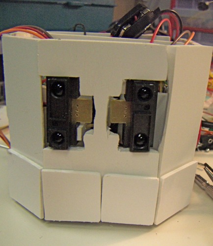
 So the sensors are now mounted to turn in parallel instead of turning in opposite directions. This way the servo connection is easy to mount and the sensors are accurately alligned, but it'l lose the abilty to widen and narrow the view angle.
I dont know if you can see it in the picture, but there is a horizontal piece of PVC hanging from the sensors in the front of the bot. The servo arm is stuck through a hole in this horizontal mover.
Another problem is programming this thing. I did expect it to be hard, but programming these 08Ms with a servo connected to the serial pin (pin0) is a bitch. The servo must not move to far out so I have to remove a jumper every time I upload a new program. If i forget then I have to put things straight inside the front area again.
Programming the motor controler is another tough one. I had it all figured out and I had a program lined up where the motor controller receives 2 bytes: one with the speed (0-127) with the last bit used for reverse, and the other with the direction (0=full left : 255 is full right).
In the end I simply couldn't get an algorithm with the right timings for these small GM10 motors. It's perfectly doable if you have only one motor, but if you try to write a dual PWM program in picaxe basic, things do not go smooth. Shorten the pulse for motor A and motor B gets relatively more looptime. This can be compensated by padding the loop with a pause, but the pause command uses 0.5 millisecond units (at 8Mhz) and the pulsout command uses 5 microsecond unit. that's simply to big a difference. I ended up with a predefined set of pulses and pauses for a couple of moves where I used trial and error to get the timing right: go_forward_slow, spin_left_fast, etc.
I added a crappy video to show how its moving now. Sorry for the quality, its been filmed with my foto camera in artificial light. Anyway : No object tracking and poor results on the dedicated motor controller. This is disappointing.
Update: Uploaded first moves video. Just a simple program testing forward, backward and spins. Oh boy, this thing is faster than expected! It doesn't run straight though. Maybe making a better connection between the screw terminals and those very thin wires of the GM10 motors will fix that. Tested electronics: OK
Update: Started assembling the body. Still need to find a way to mount the bumper skirts and to connect the IR sensors to the servo. Hopefully I will be able to test all electronics this evening.
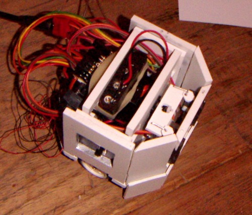
This bot will combine the mintvelt object tracker and inter-picaxe serial communication. I wanted to build this as small as possible so I build the board without the serial jacks and power will be provided by 4 AAA NiMH batteries. Details on the board can be found in a separate BLOG post.
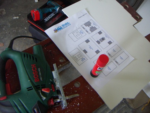
The body will be an octagon made out of expanded PVC. Instead of using a pencil to draw the pieces directly on the PVC, like I did with Edward, I decided to use printed templates. That gives much better results. Just glue the paper on the PVC sheet with a Pritt glue stick and saw away. The paper stays firmly on the PVC during the cutting, but can be removed easily afterward without leaving dirty marks.
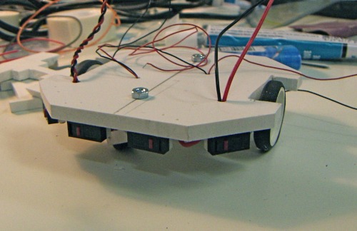
Baseplate done: Motors are glued on (hope that is stirdy enough). I use the tiny rubber wheels from solarbotics as casters. Right now they are mounted a bit to high because I didn't account for the slack off the axle. I'll fix that later.
Fixed the casters. The base is now level and stable. Bumper switches are mounted and wired. I've been gathering old ball mouses (mice?) and they each have 3 nice little microswitches. Each switch will have a small 2mm plate in front of it, that will reach down to about 4 mm of the floor.
Design is done. I did a rough drawing of all the templates, knowing some additional cutting would have to be done as I try to assemble all the pieces. Because this bot is octagonal, the angles are 135 degrees.This means scraping off PVC with a knife until it fits (sort of) I'll attach a pdf of the design allthough some parts have allready been altered a bit.
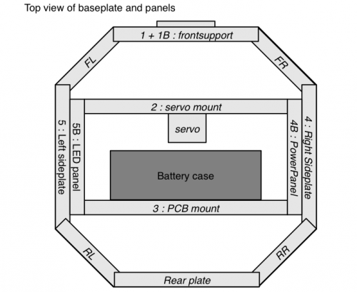
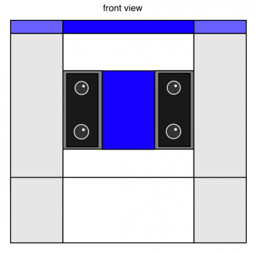
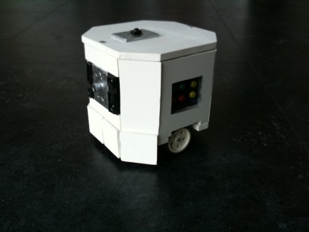
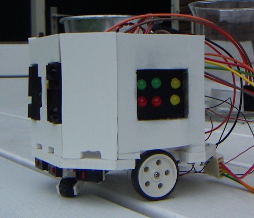
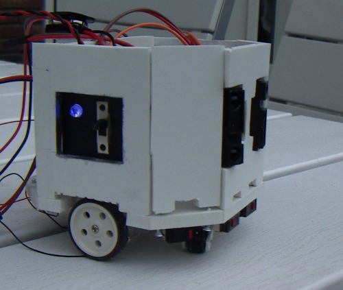
The robot will be divided into three compartments. The IR-sensors and servo in the front with the servo sticking out into the middle compartment where the battery case will be placed on its side. Also in the middle are the LED panel and the powerswitch. I left holes in the vertical plates that separate the compartments to get the wires to the back of the robot where the PCB will be mounted (also vertically on its side)
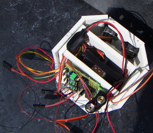
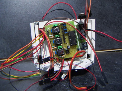
Just look at all those wires.
I'm nearly done with cutting out all the body parts. I thought the parts would come out a lot nicer when I used templates, but that is only partly true. The saw I'm using lacks precission and frankly; I lack precission too.
However I think I found a solution for this problem. I found some white adhesive foil and some black as well. This stuff is so easy to cut, I'll just stick it all around the body and cut out the holes and edges. That will surely cover up all those gaps between parts and other mistakes i made.
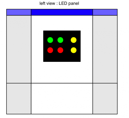
Also did the wiring for the power panel (switch and LED) and for the LED panel: a useless bunch of LEDs, connected to the motor controller and the output pins of the "brain" and the object tracker CU. Of cource the LEDs are nice colors on a matt black background.
Next steps:
- Do the last bit of wiring on the LEDS (this robot will be full of wires, just like edward)
- mount the IR sensors and construct the mechanical connection to the servo
- Test all the electronic components
- mount all the side panels
- mount the servo and the PCB panel in such a way that I can still reach them (maybe i'll make those pannels slide out upward)
- Stick foil on the sidepanels and cut out the holes
- mount the bumper-panels
- mount the skirt panels
- cut out and mount the top panel: preferably without any screws showing
follow moving objects
- Actuators / output devices: 2x Solarbotics GM10
- Control method: autonomous
- CPU: 3x picaxe 08M
- Power source: 4.8V (4x AAA)
- Programming language: Picaxe basic
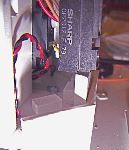
- Sensors / input devices: 2 Bumper switches, 2xSharp IR
- Target environment: indoor, flat surface