

Zumy! This is a project to keep me sane through the monotony of school.
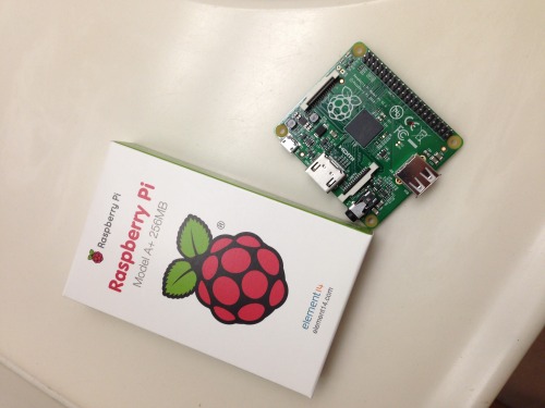
It all started with a Pi. A while back I made an attempt at building a wifi connected robot on a boe-bot chassis. After joining the military, moving, and schooling I lost track of the project. So here is round two. I bought a Raspberry Pi model A+, Pololu Zumo chassis, two micro gear motors, an arduino pro-mini 3.3v 8Mhz, a wifi adaptor, and a DRV8833 motor driver carrier.
So first things first. I messed around with the layout. My goal was to keep it as compact and low to the ground as possible. So, I mounted the Arduino Pro Mini (henceforth refered to as APM), and the motor controller on the back of the chassis. This allowed me to reserve the main mounting surface for the Raspberry Pi,(hencefort refered to as RPI). The mounting is a bit unconventional, and not the best for heat dissipation but it fit my goals.
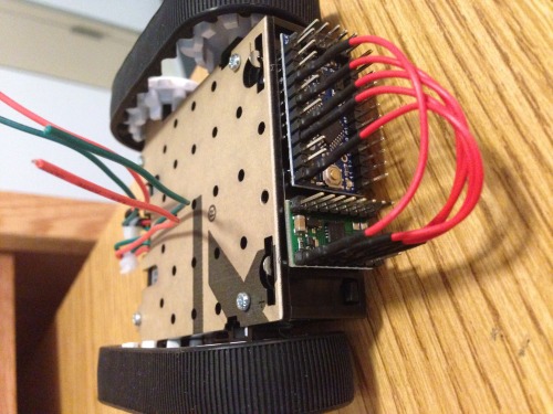
So with the layout determined and the connections made between the APM and motor controller(henceforth refered to as DRV). I set out to write a serial motor control program for the APM to control the DRV. Basically I used switch-case statements and did not allow for speed control, which was a issued I intended to fix, until something bad happened(*suspense music), which I will address later.
So the motor control program worked well enough and I mounted the RPI. I made the connections from the RPI's UART pins to the APM's. I connected a 7805 5V regulator and powered the RPI from the pins, I know it's not the best method, but again it fit with my goals. I know that the regualtor needs above a certain threshold to regulate voltage the reliably, but being stubborn I wired it to the 4AA batteries in the Zumo chassis, I even added capacitors for brown-out. As i should have expected, everytime the motors stalled the terminal voltage dropped and the RPI reset. So I went about writing some python code to communicate with the APM and provide a simple GUI. 'WASD' were my directional control keys and 'Q' activated the DRV's sleep mode. It indicated if the serial port was open, whether the sleep function was activated, and whether or not debugging data was being recieved from the APM. This worked wonderfully, but alas tradgedy strikes.
I bought a rechargable USB battery pack and mounted it to the chassis. In the midst of rewiring the RPI,DRV,and APM I used an multi-meter set to measure ohms to figure out which wire was which in the jumble of connections. I forgot to disconnect the TX pin and measured the resistance to determine which wire was which. because a voltmeter produces voltage to measure resistance, i believe this shorted the TX pin to +3.3v. Sad day. Communication between the RPI UART and APM ceased. After a good bit of troubleshooting I determined that the pin on the RPI was at fault. Rookie mistake.
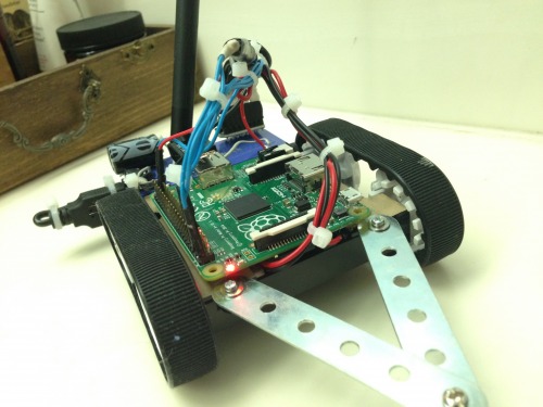
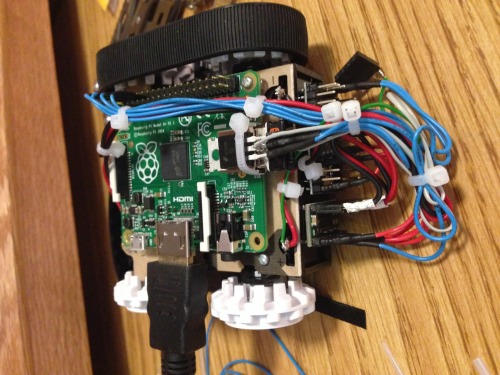
Above is the current setup. I rewired the DRV to connect to the RPI GPIO pins, therefore I have no PWM to control speed. It works quite well in light of this.
The majority of the preceding text was more or less a description of the hardware. The control aspect of this has taken many forms. Originally it was controlled via SSH and Minicom. I sent the command characters directly to the serial port. Then, still in the mindset of SSH I started to use Paramiko and write a simple gui based around that. Being a fan of simplicity, I installed TightVNC and have it start on boot. The I wrote a python program using Pyserial and the Pygame modules. It worked quite well and gave me good troubleshooting feedback. Then the incident with the TX pin occured and rather than writing a new program I used the GPIO library and use it to control the pins as inputs to the DRV which is an H-bridge. My goal is to mount a NOIR camera and a pan-tilt servo set on the front. I wanted to use an arduino to do this but since the UART port is broken and there is only one USB port I need to find a way to achieve this. The main issue is time, I am in the military and in one of the most difficult schools they have to offer, so if my updates are spaced rather far apart I apologize. I am not a software or hardware engineer, I enjoy robots as a hobby and know I do not have all of the answers, therefor any suggestions are more than welcome!
___________________________________________________UPDATE________________________________________________
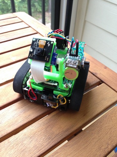
So after finishing up some very difficult schooling I finally have time to work on my bot again! I 3D printed some brackets and such for the camera. I mounted a rechargable cell phone battery to power the RPI. In the base of the zumo chassis is 4 double A's to power the motor and servo. One of the newer things I did is use a Picaxe 08M2 to be a servo controller. Initially i had a APM to provide a hardware PWM signal for the servo, i did this because the software generated PWM signal is really jumpy. So, i porgrammed the 08M2 to increment and decrement when a digital pin is turned on or off. Considering what i need the servo for this is much easier. I've been working on some socket programming to control it over the local network. I also stream the video with netcat and mplayer.
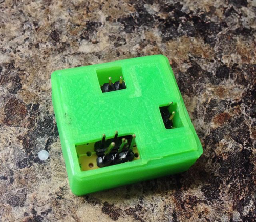
Above is the servo controller with the picaxe 08M2. More to come!
This is a companion discussion topic for the original entry at https://community.robotshop.com/robots/show/zumy
