

I've been building things like this for a while, and actually, LMR was one of the first places that introduced me to hobby robotics. I had already been building circuits with components from RadioShack for a while, but fritsl's Start Here robot was a big inspiriation. I've been building a robot each summer for the last few years, and this one is probably my 4th or 5th. I started building this in late June of 2012, and completed nearly 80% of it by the end of the summer. I finished the rest of it from August to November, mainly on the weekends.
I built this robot over the summer as a personal project, just for fun. It actually started planning it during the winter of 2011 while browsing Sparkfun and stumbling across their selection of accelerometers. I had never used accelerometers before, so the idea of making a robot that used on was pretty interesting.
Building this robot was a big learning experience, as it was my first time using/implementing/doing lots of things, such as: accelerometers, wireless communication (XBee), Arduino, serial communication, I2C, multiplexing, C++, PCB fabrication, burning microcontroller bootloader, LCD interfacing, more... So it was pretty fun.
This robot went through MANY revisions/ideas before I even started building it, as well as during the process of building it. I really had no idea that it would turn out the way it did, or even that it would actually work. Honestly, I'm very surprised that everything turned out so well.
The robot is controlled by a wireless handheld controller that contains an accelerometer. The controller detects tilt and wireless transmits information to the robot on how to drive the motors. The controller also has a circular LED display that displays the direction that the controller is tilted in / the direction that the robot is travelling.
Basically, the robot is programmed so that the farther forward/backward you tilt the controller, the faster the overall speed of the robot is. And the farther left/right you tilt the controller, the harder the robot turns in that direction, while maintaining the proper overall speed.
I've attached my code as a ZIP file. There is code for the Pro Mini, the ATmega328P, and the Leonardo I extensively used the custom library "EasyTransfer". When I started this robot, I had never used Arduino before, so I wasn't as literate with serial and I2C communication, so using this library has GREATLY helped me. Now that I know more about I2C and serial, I'll probably re-write most of the code with true I2C/serial code, but for now, I've implemented the tools provided by the EasyTransfer library. Check it out: http://www.billporter.info/2011/05/30/easytransfer-arduino-library/
Lots of the code is very relative to the actual circuit layout, so would be different in different implementations. Also, some of this code is probably inefficient, so I'll optimize it later.
I also attached a list of parts/components/tools I used.
I designed and built everything myself, but I did implement some of the ideas of others. The open-source-ness of Arduino is great :D. And that's why I'm sharing everything I've done, if anyone else wants to do something like this.
I WILL ADD MORE EXPLANATION LATER
SCROLL DOWN
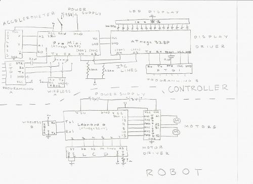
Circuit schematic of the controller and the robot.
The circuitry is pretty simple. Here's a basic schematic of the controller's and robot's circuitry. As you can see, it's pretty simple, and pretty self-explanatory. All the circuitry of the controller operates at 3.3V off of a 4.5V battery pack. The 3.3V is the output of a voltage regulator onboard the Pro Mini. The motors of the robot are powered by a 3V battery pack, and the circuitry of the robot is powered by a 9V battery, which is regulated to 5V by the Leonardo. The Pro Mini communicates with the ATmega328P over I2C, and with the XBee over serial. The serial pins used by the Pro Mini to communicated with the XBee are also used to program the Pro Mini, so there is a switch to alternate between the two options. The ATmega328P acts as a driver/multiplexer for the LED display. The LCD in this schematic is not used in the final robot, but the necessary wiring is there, as well as an empty socket in case I ever want to add the LCD back. There is a universal on/off switch on the controller for everything on the controller, and there is a universal on/off switch on the robot (which I have't drawn here) for all the circuitry on the robot. There is an additional switch on the robot which connects/disconnects the motor power supply.
The controller contains an Arduino Pro Mini, which inputs data from an ADXL335 3 axis analog accelerometer. The ADXL335 outputs a varying voltage in relation to the amount of tilt measured on each X, Y, & Z axes. The Pro Mini calculates the degree of tilt using this voltage and stores this data. The data is the processed further for use in the motor driving code and LED display code. After processing, the Pro Mini sends data serially to the onboard XBee and over I2C to the onboard ATmega328P. ATmega328P further processes some of the data and determines which LEDs to drive. The pins of the ATmega328P that are connected to the display are stored in an array, and this array is 'mapped' to the rDegree data. The ATmega328P acts as both a driver and multiplexer for the display.
The robot contains an onboard XBee as well, which is configured to communicate with the XBee in the controller. The XBee in the robot receives data wirelessly, then outputs it serially to the Leonardo. The Leonardo processes the data, determines how to drive the motors, and outputs signals to the motor driver. The motor driver simply drives the motors.
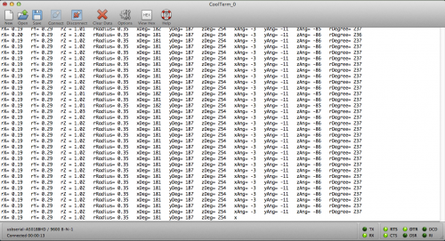
The Arduino Pro Mini processes lots of data, and can output this data serially to a computer. This screenshot shows the data sent by the Pro Mini to the computer as used in debugging. Very useful, but slows the code down, so is 'commented out' in the final code. This set of data is what is sent wirelessly to the robot and to the ATmega328P over I2C.
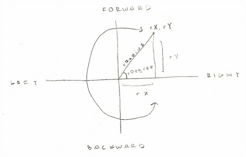
The Pro Mini, ATmega, and Leonardo all contain code (usually commented-out) that allow them to send data to the computer serially, used primarily for debugging. The rX, rY, & rZ values have a range of -1 to 1, with center at 0. They are used to determine rDegree and rRadius. rDegree is the 'direction' that the controller is tilting in, and ranges from 0 to 360, as in degrees in a circle. rX and rY are 'mapped' to a coordinate grid and the values are treated together as a coordinate point such as (rX, rY). Basic trigonometry ( a tangent function ) is used to determine the angle measure of the angle formed by a triangle the origin of the grid and the point (rX, rU). With this degree measure, I can figure out which true direction the controller is tilted in, and rDegree is used for the LED display. rRadius is the 'distance' between the origin and the coordinate (rX, rY), and represents the intensity of the tilt in any direction.
To explain the motor code, I have use the terms 'driving motor' and 'turning motor'. Basically, the robot turns using differential steering. To turn in any direction, the motor on that side drives slower and therefore the other motor overpowers it and the robot turns in that direction. That motor that changes speed while turning is the turning motor. The other motor is the driving motor. So, if the robot is turning left, the turning motor is the left one, and the driving motor is the right one.
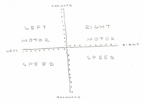
The motor driving code also went through lots of modifications. The motor driver provides 3 control inputs for each motor: PWM, A, & B. A & B control the direction of the motor, and PWM controls the speed of the motor (using PWM obviously). The present code works like this: First, the Arduino determines which direction the controller is tilted in – forward or backward, and the motors are driven in that direction. Next, it is determined whether the controller is tilting left or right. All this information is stored in single bit variables. Two variables, xAng and yAng, which come from the controller's computations, are 'mapped' to the values in the drawing below. xAng and yAng are simply the amount of tilt in degrees ranging from -90 to 90. xAng is mapped to the 'x-axis' values of the drawing, while yAng is mapped to the 'y-axis' values. So basically, the amount of forward/backward tilt becomes a value ranging from 1 to 10, and the amount of right/left tilt becomes a value ranging from 10 to 1. The information of left/right tilt is also used here to assign values. Next, the new remapped xAng and yAng values are multiplied together, this number becomes the speed of the turning motor. Then, the remapped yAng value is multiplied by 10 (the maximum xAng value) and this number becomes the speed of the driving motor. Using the information of whether the controller is tilting left or right, one motor is assigned as the turning motor and the other as the driving motor. And then it drives.
DESIGN CONSIDERATIONS:
WILL UPDATE
BASIC PROCESS:
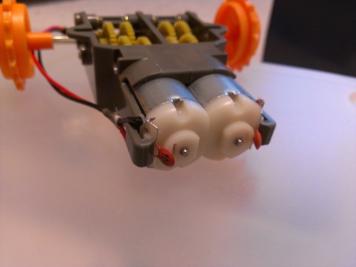
This is the gearbox I used, a Tamiya dual motor gearbox. The gearbox runs pretty well, although the 'high torque' mode still doesn't provide that much torque, which is probably due to the motors included with the gearbox. It worked okay for my robot, but I'll probably replace the included motors with some higher quality/power ones later. The gearbox also has some mounting holes which makes it pretty simple to implement in a design. I soldered on some wires to the motors, which have male headers on the ends, for easy connection to other parts of my circuit.
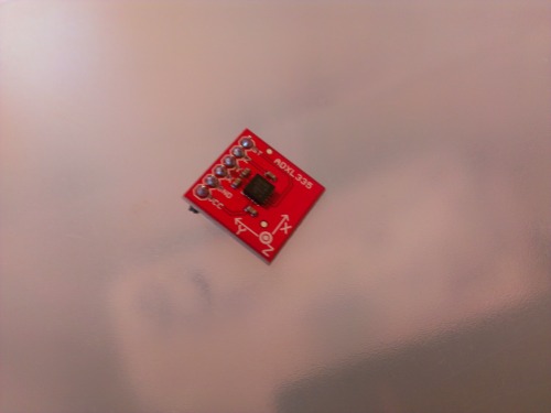
I started off by soldering pins/headers onto all of my boards and components, including the accelerometer. This is the ADXL335 3-axis accelerometer I used in the controller. It's really small, a little smaller than a quarter. This was the first time I ever used an accelerometer in a project, and although the ADXL335 has a 3g resolution, I found it to be quite sensitive. The Sparkfun breakout for the ADXL335 already has the necessary decoupling capacitors so the accelerometer doesn't require any specific external circuitry to be used. The board has a X, Y, and Z pin, each which output a varying analog voltage in relation to the amount of tilt detected around each axis.
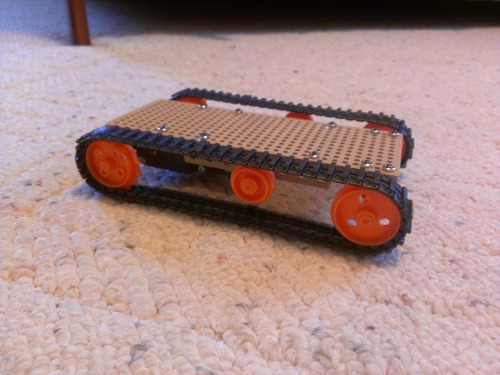
This was my original design for the robot's tracks/wheels, with one long, straight track on each side. When I drew it out, it looked pretty cool, but after testing out the design it became apparent that such long tracks would create too much friction and make it extremely hard to turn. Also, there wasn't enough tension between the wheels, so this design was very inefficient. I also decided here that I would have to use a custom material, which ended up being wood, for the base/body of the robot rather than the pre-made plastic mounting board from the track/wheel kit.
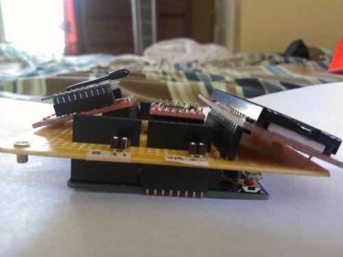
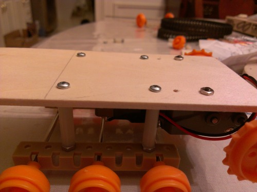
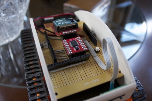
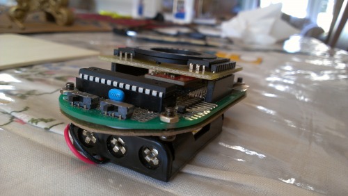
Side view of robot circuitry. On the bottom is an Arduino Leonardo.
The wiring of the shield. The two sockets on the edges of the board are for the motors.

The finished custom 'shield' for the robot, which mounts onto the Arduino Leonardo via male headers. The board has sockets for the XBee, motor driver, and LCD, although the final robot doesn't contain the LCD due to size constraints. There are also sockets on the bottom edges into which the connectors from the motors plug. The small board attached to the main board via a ribbon cable has 2 slide switches – one for complete on/off of all of the circuitry on the board, and another for connection/disconnection of the motors' power supply. This allows for easier debuggin and programming; when I need to program the Arduino, I can power off the motors so the robot doesn't drive away. Later, I might add some visual or audible indicators for the switches because it's easy to forget to turn them off sometimes.
Unlike the controller I didn't bother building the robot circuitry on a breadboard since it was pretty simple to solder/build the finished shield and a lot easier to work with once mounted on the Arduino. The shield PCB is from Radioshack.
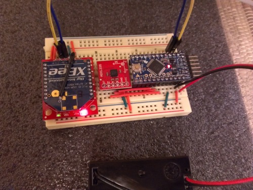
The first prototype of the controller, on a breadboard. On the right is the Arduino Pro Mini, middle is the accelerometer, and left is the XBee wireless tranciever, all powered by a 4.5V battery pack. This is actually the design I used for all of my testing and programming of the accelerometer, XBee, and motor driving code.
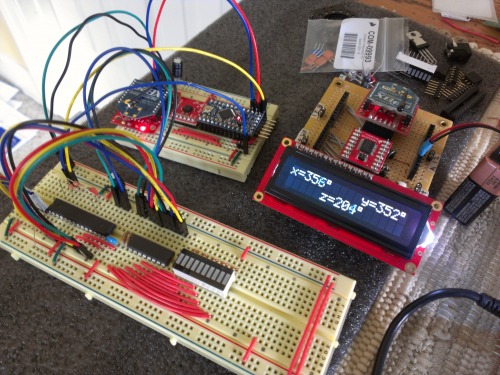
This is the complete breadboard layout for the controller along with the finshed robot circuitry. On the longer breadboard is an ATmega328P, with a 3.3V 8MHz bootloader. I had bought the ATmega328P from Sparkfun with the 5V 16MHz Arduino bootloader already burned onto it, but because I had to use the chip in conjunction with the Pro Mini, which runs at 8MHz at 3.3V, I had to burn the bootloader onto the ATmega myself. I think I ended up burning a Lilypad bootloader onto it. I didn't own a proper ISP, so instead I actually used the Arduino Leonardo as an ISP, and burned the bootloader onto the ATmega328P using it. I don't quite remember how I did this, but I found some code online. Check out these links:
http://petervanhoyweghen.wordpress.com/2012/09/16/arduinoisp-on-the-leonardo/
http://arduino.cc/forum/index.php?PHPSESSID=55ab3755a5e3c4e789347ed115bebcde&topic=108270.15
On the top right is the finished robot circuitry, with an LCD mounted for debugging. The Arduino interfaces with the XBee on the shield, which receives data from the XBee connected to the Pro Mini on the controller. The Arduino then outputs the X, Y, and Z values – in the form of 0 to 360 degress – to the LCD. The LCD made the code much easier to debug than using a computer. The board that the LCD is mounted on is wider than the rest of the shield, so I ended up removing it in the final robot, but the socket into which it plugs is still on the board, so if I find a smaller LCD with the same pinout, I could add the LCD back. The entire board is powered with a 9V battery. I usually steer away from using 9V batteries in robots due to their low current output and short life, but because the final robot doesn't contain the LCD, the 9V works pretty well.
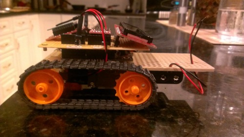
The first 'working' prototype of the actual robot. It was just to test the driving code (which I ended up scrapping), but the tracks were too loose and although it did work, it couldn't turn very well and only lasted a few minutes. The wires from the motors and battery pack were fed through the holes in the base.
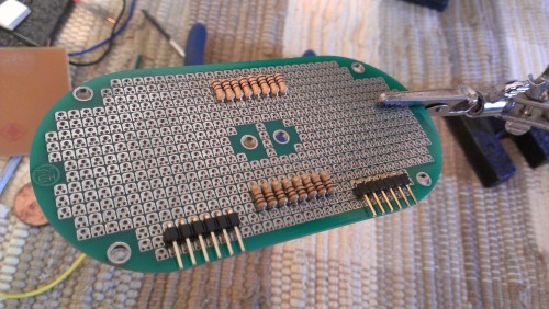
The board I used for the controller. My original design was very very different from how I ended up constructing the controller. I pretty much made up the design as I went along, and there was no real planning involved in the layout of the components on the board. Very surprisingly, it turned out pretty great. The PCB I used (purchased from Sparkfun) has an interesting design, in that each solder pad actually contains 3 holes – one large one and two smaller ones – and this design GREATLY improved my wiring design versus anything I've done before. I really recommend this board.
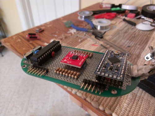
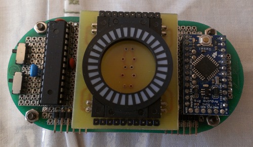
This is the nearly finished controller (the female header sockets for the LED display, which should be adjacent to the resistor rows). Unfortunately, I was so preoccupied with getting this right that I didn't take any pictures as I made the controller. The small red square board in the center is the ADXL335 accelerometer. I had soldered male swiss machine pins onto the accelerometer, and then soldered that onto the main PCB. On both sides of the accelerometer are rows of resistors (16 total) for the LEDs in the display. On the right of the board is the Arduino Pro Mini. I had also soldered male swiss machine pins onto the Pro Mini, and then inserted it into two rows of female sockets. On the left of the board is the ATmega328P, which communicates with the Pro Mini over I2C and acts as a driver for the LED display. Along the bottom edge of the controller are 2 sets of programming pins, one for each microcontroller on the board. To program either microcontroller, you just plug in the FTDI board directly into the pins.
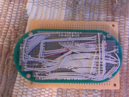
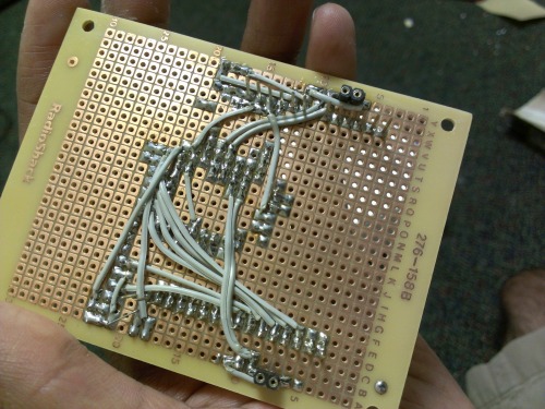
The wiring of the controller. I didn't really plan any of the wiring layout either, but everything ended up fitting pretty nicely. I came up witht the wire layout as I went along, and it was tricky at times, and as you can see many of the wires pass over each other. I also soldered on some 'brackets' using clipped resistor legs to secure some of the wires down to the board. I used the individual wires from an old ribbon cable, which allowed the all the wiring to be very low profile. I think it ended up being only a few millimeters thick. I soldered the XBee board into the row of holes on the far left of the controller board, using male header pins.
Because the circular LED display I wanted to use had an odd pinout arrangement, I had to fabricate my own PCBs. Before this project, I had never done PCB fabrication, so I was initially skeptical and considered having it made by a paid service, I decided to undertake the task for the sake of experience... and to save money (I actually ended up spending more than I would have if I got them made for me). I designed the PCB layout in Eagle and printed the desgin onto HP Glossy Presentation Paper using a laser printer. I then ironed the design onto the bare copper board. For more information, just search up "homemade PCB"
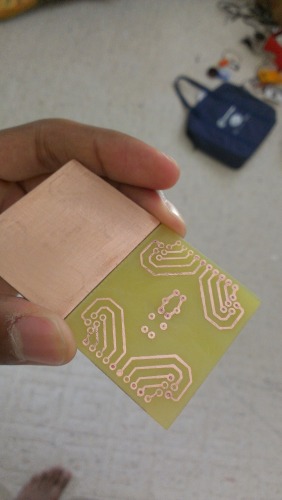
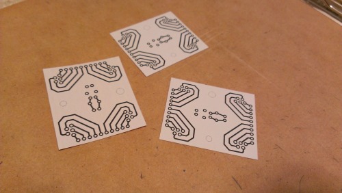
The final cut-out PCB, prior to etching, on the left, next to the first finished PCB on the right. I ended up also etching the board on the left and used that one for the final controller because it was much better made.
I cut the actual PCB out of a large sheet of copper clad FR-4. I simply taped the cutout for my design onto the end of the board, and held it in place using a table mounted vice. At first I tried scoring the board using a scoring knife (which was horrible and did absolutely nothing) but ended up clamping a ruler onto the board, with its edge along the edge of the paper, and using a retractable utility knife to score/cut the board. It took around 10 minutes total, and it worked surprisingly very well.
I used Jameco's PCB Etching Solution as my etchant. It's a mixture of hydrochloric acid and water, so for safety reasons I didn't take any pictures of this step. I poured a small amount of the etchant into a small plastic container, and wore plastic gloves and a face mask for protection. The entire etching process only took around 10 minutes. If you want to find out more about PCB etching, search up "homemade PCB fab"
This is the first finished PCB I've ever made, and as you can see there are a few defects. Some of the traces didn't form properly and some got 'squished' or flattened out in the process of ironing the printed design to the copper. I ended up making a 2nd PCB for the final robot, and that one turned out almost perfectly. I don't have any pictures of it though.
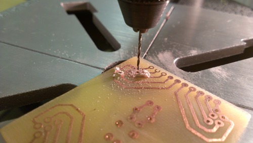
I drilled the holes for the PCB with a Dremel 4000 rotary tool, mounted on a Dremel Workstation, which acts as a drill press. I read a lot of bad reviews about the Dremel Workstation and wasn't expecting it to work very well, but it ended up working really great. I used size 1/32" drill bits (super super small) made of steel. I was planning on using carbide bits, but the steel ones worked great. I even managed to only break 4 :) . I drilled a total of 50 holes on each PCB (I made 2). After I was done, I realized that the pins on my LED display were wider than regular component leads – and wider than my drilled holes – so I had to go back and 'widen' the holes by running the drill bit through each drilled hole while very slowly moving the board around. I managed to break a few bits doing this.
In the end, the LED display and the male headers fit the PCB pretty well. Fabricating the custom PCB was probably the most stressful and time consuming part of this project since I was brand new to pretty much all of it.
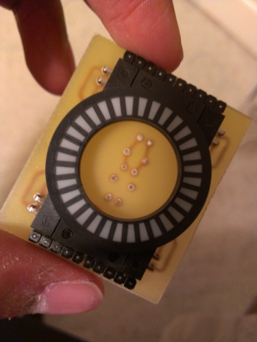
The LED display soldered into the custom PCB. There are some unused holes/traces in the center of the board for an optional button or switch.
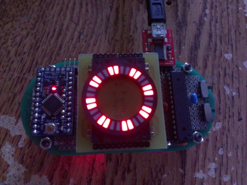
This is the first test of the LED display mounted on the controller board. The display contains 16 red LEDs, each LED illuminating 2 segments. All the LEDs are driven directly by the bare ATmega328P (using 16 outputs). The ATmega328P communicates with the Arduino Pro Mini via I2C. The ATmega328P is also directly programmed and contains all of the code necessary to determine how to drive the display.
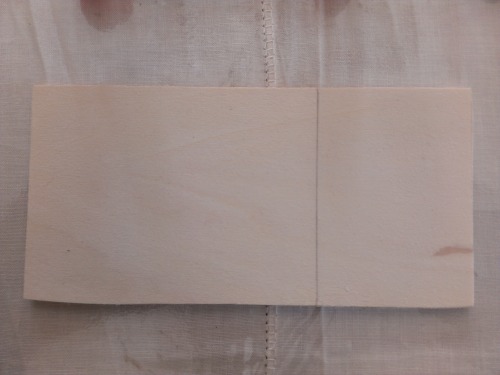
I cut the base for the robot out from a panel of basswood. It's pretty strong yet easy to cut and drill. Very very surprisingly, I had just randomly chosen a length for cutting out the base and was planning on cutting it down as I finalized the design of the robot, but somehow everything managed to fit almost perfectly without having to modify the length of the board. My biggest problem with the construction of the motors/wheels/tracks on the bottom of the base was maintaining proper tension and length of the track. For quick prototyping of the positioning, I used hot glue to temporarily mount the gearbox and axle mounts on the base. I spent quite a long time finding the proper length for the track and the right amount of tension required. Also, the width of the base had very little tolerance in size due to the size of the circuit board and the required side panels having to fit, so I had to take extra precaution to allow the tracks enough wiggle room so as not to scrape the side of the base.
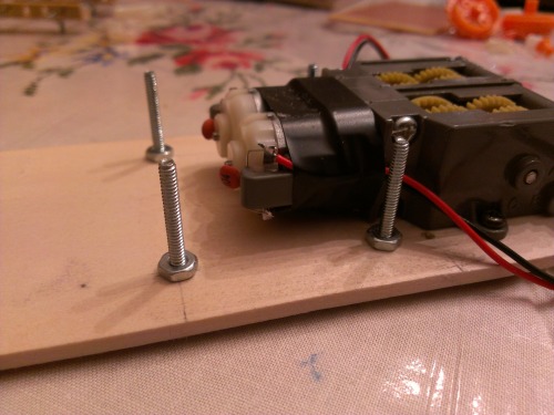
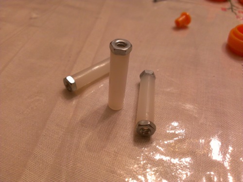
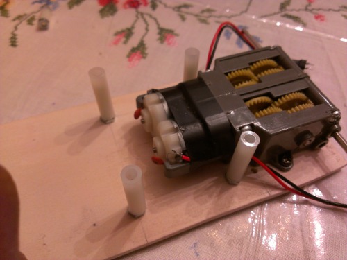
Small plastic spacers with nuts superglued to the ends. These are screwed onto the screws sticking out of the wood. Very simple. Then, another screw secures the other end of the spacer onto the axle mount.
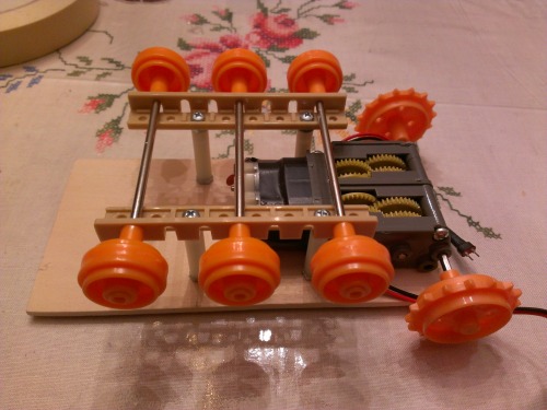
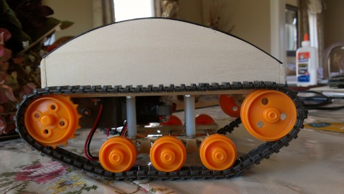
I realized early on that using a tank treads drive system would be pretty innefficient, as the treads would create lots of friction with the driving surface and cause difficulty turning. Also, I would have to maintain proper track tension – not too loose but not too tight. My original designs were centered around the tracks being simply stretched completely straight, held between the back and front wheels, but I found those to create far too much friction with the floor and make it impossible to turn. To limit the friction and ensure easier turning, I added 3 sets of middle wheels to my track design. Therefore, the surface area of the track in contact with the floor is much smaller, and the middle set of wheels acts as pivot points in turning. It works pretty well, although I didn't drill the holes as precisely as I should have and in effect, the middle wheels are closer to the front axle than the back axle. Because of this, the robot turns better when driving forward than when driving backward, but it still works pretty well.
Tops of the screws sticking out of the top of the base, which necessitated the need for an intermediate cover.
Intermediate cover cut out from an old mousepad.
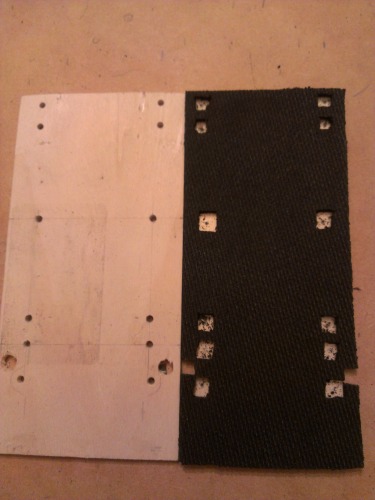
This is the finished base board, with all holes drilled, along with the 'cover' for it. After mounting the gearbox and all the wheels to the base, the tops of the screws/bolts stick out slightly on the top of the base where all the circuitry and batteries are supposed to go and create a very uneven surface. To ensure an even surface on the top of the base, I cut a piece out from an old computer mousepad. The top of the mousepad is a thin hard plasic and the bottom is a right foamy material. I cut small holes in the foam bottom (for the tops of the screws) and it fits very nicely.
Notice that the black pad is less wide than the wooden base to allow some room for the side panels to be mounted. There are also 2 large holes in the base for the wires from the motors to be fed through.
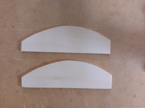
I cut the 2 side panels out of the same piece of wood I cut the base out of. I just drew the curve for the top of the panels by hand onto a sheet of paper – after measuring the basic minimum heights at certain points along the curve – and cut the curve using an X-ACTO knife. Actually, I cut most of the wood for this robot using an X-ACTO knife (my hacksaw is old and cuts very roughly) and it worked very well.
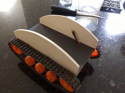
The two side panels attached to the sides of the robot. I attached them with basic All-Purpose Glue (school glue). The bottom edges of the panels rest on top of the exposed edges of the base board. The bottom outer edges of the panels form a perfect edge with the edge of the base and the black inner cover.
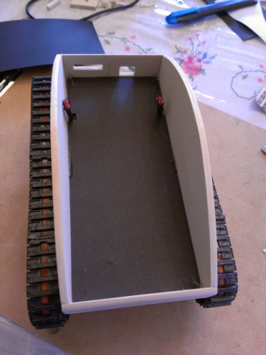
And now the front and back panels are attached, also with glue. The top edges of both panels are slightly beveled to match and continue the curve of the side panels. Note the back panel has a small thin slot for the switches and a larger access hole for the USB cable used to program the Arduino in the robot. Both panels are mounted onto the 'front' edge of the base, rather than the top edge like the side panels.
Top front.
Top back.
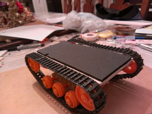
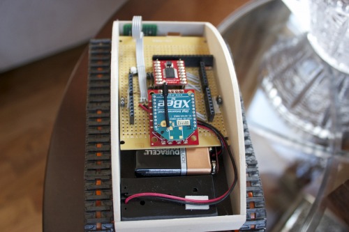
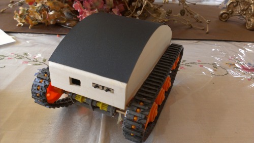
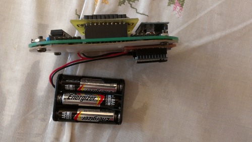
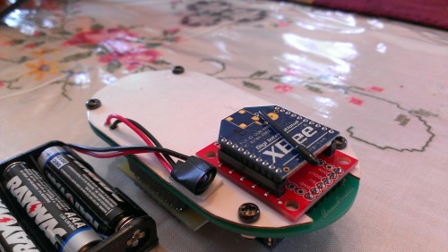
And these are pictures of the finished robot, without a top cover. The PCB fit perfectly inside the enclosure, and the batteries are held in the front of the robot, which also fit perfectly.
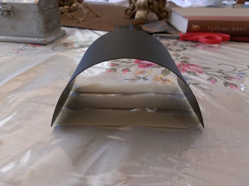
I cut the top cover out of the cover of a spiral bound Mead notebook. It is a thin, flexible, yet strong plastic, with a matte surface. I had to tape it like this for a few days to bend it into the proper shape. I also used an X-ACTO knife to cut a tiny 'hinge' in the underside of the plastic, which allows me to open up the cover to change the batteries if needed. The 'hinge' is pretty durable.
FINISHED ROBOT!
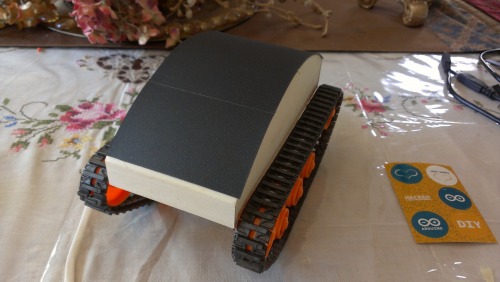
Finished robot with top cover mounted. The top cover is attached to the side panels with hot glue, which seemed to be the only thing that would stick it. I might paint the wood of the body black to match the color of the top cover.
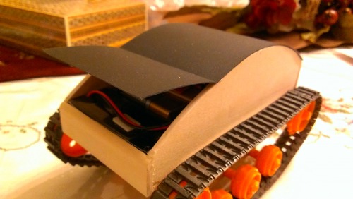
The hinge I cut in the top cover open. The hinge is used to access the batteries.
Back of the robot. The hole is for access to the USB port of the Arduino Leonardo, used in programming. The left switch is used to connect/disconnect the motor power supply, while the right switch is a complete on/off of all the circuitry in the robot.
FINISHED CONTROLLER!
Finished controller. Probably the best thing I've built.
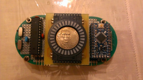
Size comparison with a nickel, which happens to fit perfectly inside the display. Woah.
The small switch on the left (from this perspective) is a complete on/off switch for all the circuitry on the board. The second switch lets you choose between programming the Pro Mini and letting the Pro Mini communicate wth the XBee, as both require a connection to the Pro Mini's serial pins, which it only has one set of. The small red board underneath the display is the accelerometer.
The wiring on the bottom is covered up by a piece of thin stiff cardboard. It is secured to the PCB with 4 small screws. Also, the XBee is mounted on the bottom of the controller.
As you can see in the size comparison with the nickel, the controller is pretty small. Everything fits nicely within the shape formed by the PCB. On the bottom there is the battery pack and the XBee, which is soldered through the holes on the edge of the board using male headers.
IMPROVEMENTS:
Most importantly, I still need a proper enclosure/case for the controller. Any ideas?
The motors I used aren't that strong/high in torque, so I'll probably end up replacing them.
The code isn't as streamlined and efficient as it should be, especially my implementation of serial and I2C communication, so I have lots of code optimization to do. Also, I am working on expanding the functionality of the display, such as to integrate response to the intensity of tilt.
The circular LED display I used is sold by Sparkfun, and at the time I made this robot, they only sold red versions. Now, they sell the displays in green, blue, and yellow. I'll have a few of my custom PCBs made by a fab house, and make some displays in other colors.
Currently, the robot's circuitry is powered by a 9V battery. It is small and lightweight, but has a very short lifespan and is inefficient. I'll probably change the power supply to something more robust.
Since the tank treads are somewhat inefficient, I might even build a new robot that instead has wheels instead of tracks. This robot would still use the controller I've built. This also ties into an idea for my next robot.
MORE:
So making this robot was really fun, and I'm planning on building a new robot next summer, which is currently planned to be a self-balancing robot that drives around, controlled by the same controller I built for this robot.
Since the controller is modular, as in I can interface the onboard XBee with anything I want, the controller I've built can be implemented in anything I make that has an XBee.
And I'll probably also post my other robots in some time.
And I'm still updating this post, and will probably add more information. If you have any questions, feel free to ask. I'm happy to share.
Navigate around, controlled by wireless tilt/accelerometer enabled controller
- Actuators / output devices: tamiya dual motor gearbox, circular LED display
- Control method: Wireless (Xbee transceivers)
- CPU: ATmega328P, Arduino Uno (ATmega32u4), Arduino Pro Mini (ATmega328P)
- Power source: 9v battery, 4.5V battery pack (3xAAA), 3V battery pack (2xAAA)
- Programming language: Arduino C++
- Sensors / input devices: ADXL335 3-Axis accelerometer
- Target environment: Indoor/smooth surfaces
This is a companion discussion topic for the original entry at https://community.robotshop.com/robots/show/wireless-tilt-controlled-tank-robot
