Nope
From what I know, the ONLY differences between the Atmega 328 and 168 are related to memory:
- the size of the flash program memory (32KB vs 16)
- the size of the EEPROM (1KB vs 512B)
- the size of the SRAM (2KB vs 1)
Hope this helps,
dan
Nope
From what I know, the ONLY differences between the Atmega 328 and 168 are related to memory:
- the size of the flash program memory (32KB vs 16)
- the size of the EEPROM (1KB vs 512B)
- the size of the SRAM (2KB vs 1)
Hope this helps,
dan
need to check
This is a first time i use i2c comunication and still not good with programing
i use ATmega8 minimum system as the processor, CodeVisionAVR for compiler and this is my project
http://www.mediafire.com/?2ss8cqi8pg6uegq
this program use to show the output from ir camera to lcd, but look like this program is not complete… i don’t know how to fix it… i’ve try to use ATM18 project but… very hard to find atmega88 in jakarta (indonesia) and i need ito finish this project before december. anyone can fix my program? thx in advance
I only skimmed but… wow…
I only skimmed but… wow… not sure where to begin here. That collection of files is confusing because it looks like Arduino code, with strange file extensions (.i is non-standard and the file mixes together typical header contents with code)
You might consider that you’re attempting too much in too short a time. I don’t think anyone is going to do your project for you. But if you want to learn, you might find it easier to overcome your obstacles by using the Arduino programming environment, I think.
Either you have to go buy an arduino-compatible board or you’d need to figure out how to set up your ATmega8 for use with Arduino. Normally Arduino-compatible boards have an ATmega with a bootloader on them. Which means you have to be able to flash a bootloader onto your ATmega8. Then you can program with a usb to serial adapter that breaks out 5v, rx, tx, and dtr (for reset)
http://arduino.cc/en/Hacking/Bootloader?from=Main.Bootloader
Once you have that, you can program in the Arduino IDE and make use of built in I2C libraries, etc.
http://www.arduino.cc/en/Reference/Wire
There are a number of cheap Arduino clones available but not sure what is possible for you to obtain in Jakarta whether thru internet or locally or whatever else.
actually, the .c file that
actually, the .c file that you need to look. the other was product after i built this program…
but okay… i’ve done by upload the bootloader.hex file and set the fuse via atmel avrprog with codevisionavr and yes, atmel avrprog didn’t recognize by arduino… so, i’ll try with paralel port later… thx before
Ok, I admit ignorance
Ok, I admit ignorance regarding your IDE. Sounds like you are much farther along than I originally thought. Sorry.
Where is the I2C library?
Hopefully the parallel port programmer will work.
If it compiles then I guess you are good to go. The code looks like it’ll do what it needs to do I guess?
Breakout Board for Wiimote Camera
https://sites.google.com/a/rocketbrandstudios.com/rocket-brand-studios/wiicamera
okay… i hope this will be
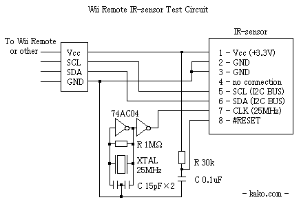
okay… i hope this will be the last question. actually, i can’t find the oscilator also ( only around 10mhz ) in jakarta, and it say that need to be order first and will take 3 months (duh) so i use the crystal with capasitor and of course, i use kako schematic for my ir camera driver with little modification so the vcc will be drop to 3.6v and put a pull-up res in sda and scl. the question is… is it still can be use? sorry for my bad english…
Kako’s clock signal circuit
Kako’s clock signal circuit should work fine – I used the same circuit for a TTL-based oscilliscope calibrator (http://www.bot-thoughts.com/2009/08/oscilloscope-calibrator-part-1.html)
As for supply voltage, I ran mine off 3.3V, never higher. I don’t know what the max ratings are for the camera. I’d think 3.3V would be safest. What is powering the AVR? Can you put another linear regulator in parallel or in series? Even a restor and 3.3V zener might work.
ok… its kind of
ok… its kind of confusing… i modified again the signal circuit so the vcc for camera about 3.2v using 220 ohm and 470 ohm voltage devider, using this 3.2v to pull up the SDA and SCL using 4k7 ohm… set the scl to analog input 5 (PC5) and SDA to analog input 4 (PC4)… set my avr910 to serial… opening wiiblobtrack… nothing happen
i though that my camera was already dead, and buy another wiimote… take the camera, and again… no respond… using wii ir sample from here… cannot connect to wii blob track… opening serial monitor on arduino… no respond…
take back the camera to wiimote… the wiimote works well…
my question
1. is there something wrong with my pin configuration?
2. How to use serial monitor?
thx
note : i try use this program, because include serial print to test using serail monitor…
Using a voltage divider as
Using a voltage divider as VCC for the sensor is not a good idea. Better use 2 diodes in series, as shown in the schematic.
Did you use a 74x04 together with the crystal quartz as shown in Kaku’s schematic?
Any chance to see a photo of your work?
Questions about camera performances
Hello,
I’d be interested to use this setup to track the position of a hand in three dimensions.
However I’d like to have an idea about the sampling rate of the data. Does anyone know it ?
Also, does the sensing work well in a very short range (0 to 50 cm) ?
Thank you in advance.
The sample rate should be
The sample rate should be 200Hz, when using I2C. Here is video about this:
http://www.youtube.com/user/sha433#p/a/u/1/ssMlodh2n4U
You will need a glove with IR LEDs or reflective material on your fingers and a IR LED beamer. Johnny Lee has done this. The video shows how it works:
http://www.youtube.com/watch?v=0awjPUkBXOU&feature=relmfu
Never tested it by myself but would like to hear more about it.
200 Hz ? Great ! In between
200 Hz ? Great ! In between I’ve read somewhere that it was only 100 Hz, so it’s even better !
Yes I saw Lee’s video. This might be really interesting. One question: is his setup is there any technical reason to put all the IR LEDs so close to the camera ? Wouldn’t it be better to spread them on a bigger surface ?
Don’t know if 200Hz is the
Don’t know if 200Hz is the real sample rate, maybe it’s only the maximum sample rate for reading the sensor with I2C.
A single IR point source would be the best, I think. Spread the LEDs on a bigger surface, will give you different reflections for each finger.
Additional questions
I managed to extract the camera from the Wiimote and have alost finished to solder it on new wires. But before trying to build the circuit I’d like to ask additional questions:
1. Is the 25 MHz crystal necessary ? Couldn’t this signal be generated by the Arduino board (I am using an Uno) ?
2. As the Uno has a 3.3 V output is the voltage conversion from 5 V necessary or not ?
I think AVR is limited to a
I think AVR is limited to a clock signal of fclk/2 so on Arduino that’d be 8MHz. The mbed I used is running 96MHz so 25MHz is no big deal. Easy enough to just use a separate 25mhz crystal/oscillator/clock thingy.
That seems logical.
That seems logical. Thanks.
What about the voltage ? Should I use the 5 V output and additional components or the 3.3 V output ?
Very fragile connectors
Hello,
I have tried to solder wires on the camera’s pins but it’s really hard. After having managed to solder all of them I pulled on one wire and the complete pin went out from the camera. So I would recommand to attach the camera directly to a PCB as in the article.
I had no choice but to cut the black box containing the camera. You can see the pictures in the official Arduino forum. The sensor has eight copper lines with a 0.875mm pitch (SMD standard ?). So it appears even harder to solder…
My clock has only two pins, not three.
I figured out that the clock oscillator I bought is a bit different than the one shown on the diagram. Mine looks like this:
As you can see it has only two pins. Is is also written “24.000 QIC” over it. Can I use this component ? Can I power it with 5 V ? Do I connect the other connection to the sensor’s CLK input ?
This is a crystal oscillator
This is a crystal oscillator not a clock oscillator. But you can build a clock oscillator from it with a circuit like this (X1 is the crystal oscillator).
Kaku has been used a similar circuit with a crystal oscillator: