

After many, many tests and trial runs, I have started cleaning up Walter's electronics and mechanics to a state that is a little bit closer to what it will be when done. I decided to start a new post about Walter as the last thread is quite long anddocuments most of the "getting it working" tests. This thread should be about building the final project.
***Update 4.2.09***
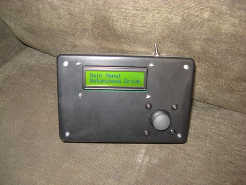
Head moves, remotes and autodrive... All found in top video **TING!**
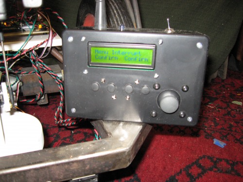
I have finished my new remote in adding 4 "soft keys" below the LCD. This allows me to select any of the options displayed on the LDC above. I am able to toggle between RC and Auto drive as well as many other options. During RC mode, I have installed a "reverse lockout" which prevents the wheels from being inadvertantly clicked into reverse at high speeds --this could either be driver error but more, just a small bit of bad data being sent or received. I have overcome my problem of noise coming from my Sharp sensors by simply turning them off for RC drive and on for auto drive. When they are on, an IR signal, instead of a RF signal is used to return to "menu mode".
I have built a new teaching pendant for encoding head moves using a playstation joystick, which requires less travel than a std. pot to get from 0 to 255. Also, the "rotate" is geared to modify a 3/4 turn pot into a 1/2 turn. I included nice big start and stop buttons used during recording and I wired a 9-pin d-sub connector to allow me to quickly plug it into walter.
I have cleaned up some sensor limits during auto drive and again, improved the "stuck in a corner" code. I have a good start on syncing the head moves (slave) with the drive code (master)
Coming Up:
Adding my Wheel Encoders
Adding a PIR motion sensor
Adding some "curb-feelers" --Some actual bump-switches to deal with chair legs and the like that the distance sensors miss.
Doing some recoding for some more personality (head moves, etc.) during different driving actions.
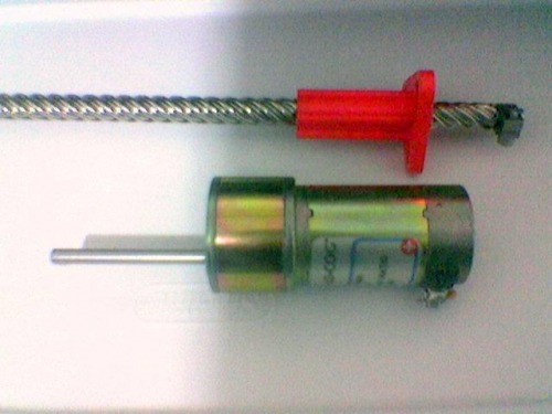
Starting work on Walter's arm! --Thank you so much pravoka !!! --He has been good enough to send me the very first (and most important part for walter's arm...
***Update 3.14.09***
As you may have seen in the blog post "Walter... Fail", I had run into some pretty big issues with Walter's initial set-up. We have gone through a full tear-down and now, are back in the ball game and steering toward much better results. The major problems I had was the fact I had no designated master and slave, and many serial and I2C lines were shared by both the head/display picaxe and the drive chip. Now, I have a much better Master/master/slave system. First, instead of menu options (auto drive, RC drive etc) being on-board on the display chip, they have been moved to a 28x1 inside of my new remote. This constitutes the first "master" which has first priority over all other chips via an inturrupt then a serin "everyone stop and listen to the remote" command. Second, the drive chip is the on board master. In terms of the automous drive (which is really what this update is about) the head/display chip simply sits there and waits for commands from the drive chip in terms of when and where to move the head. There are no "handshakes" anymore and each chip has it's own servo driver now --no more sharing I2c lines, no more "I'm talking -you wait" crap.
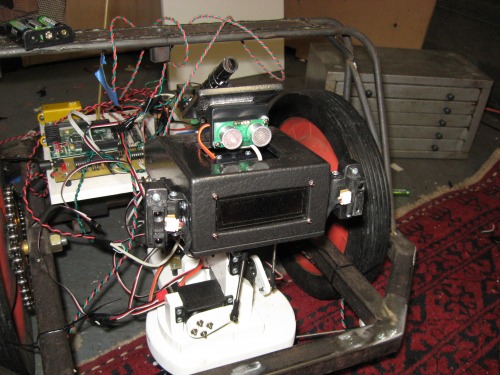
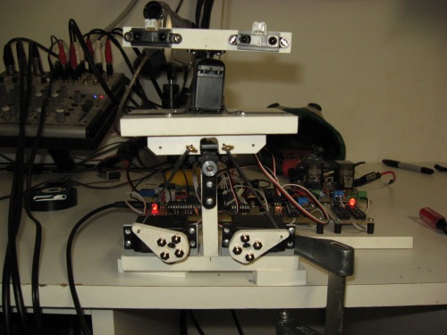
I discovered quickly the top-of-the-head mounted sonar was no good... Simply too far up and was just not effective for auto drive. I have moved it to the underside of the chassis and also added 4 sharps. 2 sharps catch the corners of the chassis where the sonar is blind, while 2 more shoot straight forward. Because the sonar is "sweeping" there is a chance it could be looking right as something suprises it on the left -The 2 fwd sharps are simply a low-accuracy back-up for the sonar. I am still working on cleaner "stuck in a corner" code as well as adding more head (personallity) moves to be sync'ed with the drive moves. Eventually, I would like to mount all the sensors sunken into the edge of the chassis for a snazzier look. Word.
The Remote:
The remote is simple eonugh. Radio shack box, play station joystick and Picaxe LCD. For now, being as broke as I am, I can't afford any RF units so on one side there is a 1/4" mono earphone jack used for a patch cable down to walter. Yes, it is a "wired remote". --Does anyone remember when VCR's had them? At any rate, I am using simple serin/serout commands. Walter has a 14m onboard (also connected to the remote) who's only job is to sit on a serin command waiting for any data to come. When the 14m is triggered, it sets an output high triggering inturrupts on the 2 main 40x1 chips. The drive chip and head/ display chip then simply goto to a "I'm waiting for info from the remote" chunk of code and respond accordingly. Having the extra 14m keeps me from having to waste time on either of the main chips constantly looping back to check a serin pin --Inturrups are wicked faster.
Overview:
I am much happier with this rebuild. I have been working much slower and getting each chunk solid before continuing. This is advice I have given many people, I just now seem to be listening to my own advice.
Chris begs for free parts:
Just to throw this out there... I have no money, and it can't hurt to ask, so if anyone wants to make donations...
You will be rewarded in Heaven or in Karma or in the next life you won't be a slug...
Needed:
RF TX/RX units -Even the cheap ones (begger can't be choosers) just data-in, data-out
SLA batteries --I need 6v and 12V as well as a charger. (the charger is less important) The 6v can be anything, the 12v must be at least 18ah or higher.
IRFZ44NPBF-ND MOSFETS N-CH 55V 49A TO-220AB (I am down to my last pair... one more smoke and walter looses his drive)
Chocolate Cake (Homemade with cream cheese icing)
--See I don't ask for much!!
***Update 2.24.09***
The head is done! Each of the Sharp IR sensors are independantly controlled with individual servos, as well as the IR beacon sensor on top and the pop-up sonar. The "IR Beacon" is simply a standard IR sensor (the kind that works with Sony codes) stuck at the back of a long tube. In this configuration, the sensor will only see an IR beam from directly ahead. Tie this with the posistion of the servo and Walter will be able to drive to a "beacon" be it a recharge station etc. The sharp sensors are posistioned in an object follow set-up. I have also ditched the large wooden board I had everything mocked-up on and have started hard-mounting parts to the chassis. Two more sharp sensors are mounted below the frame and can rotate from directly fwd to 90 degrees out to the sides.
Included in the video is a simple demo program to show off my coolie pop-up sonar!!
***Update 1.17.09***
I can officially program all of Walter's head moves in real time into my EEPROMS. I could type for hours here, but it would be best to simply watch the video. I am starting to feel that each of these "sub-systems" are becoming more solid so I might be getting close to a "semi-perminate" mounting of all these parts on to the frame. I still hesitate a bit, as all these head and eye movements seem to be taking a lot of processing so I might have to add a second 40x1 which would change my main "brain board" a little. At any rate, go watch the video!!
***Update 1.10.09***
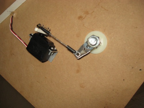
I have the finished the basic idea of Walter's head and got my LCD working. At this point, I am trying to figure out the most efficent way of controlling 3 axis of movement with the most use of EEPROM space and the least amount of variables. I also need to play with the geometry of servo arms and push rods I am using, I think I can get a lot of the herky-jerky out of it. It will look pretty good though, when it is all sanded down, filled and painted.
The next thing you should see it all of this actually on Walter and in good, smooth opperation.
First off is the main board...
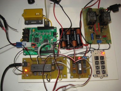
I custom made PCB's for the Main 40x1 (with 14m helper), the 20-Servo Driver, Motor Driver and (8) 256 EEPROM's. The wires need to be cleaned up a little, but this will be the basic set-up.
I also finished welding Walter's trailer hitch:
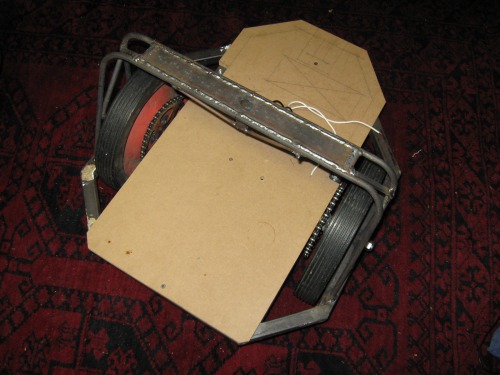
The welds still need to be ground-down, but there it is. Now, you are probably asking "why is the trailer-hitch in the middle?" Well, if it was in the back, and the robot turns on it's center, the trailer would just get wrapped around. With the hitch on the center line, and a long tounge on the trailer, the robot can still spin a 360 with no problems.
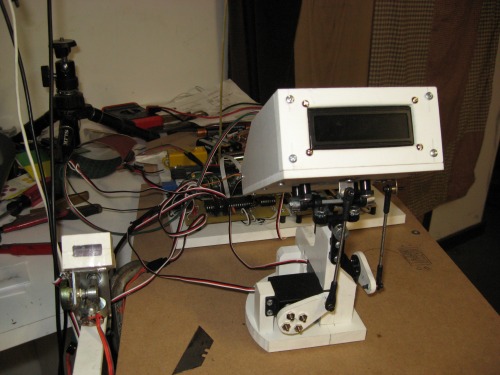
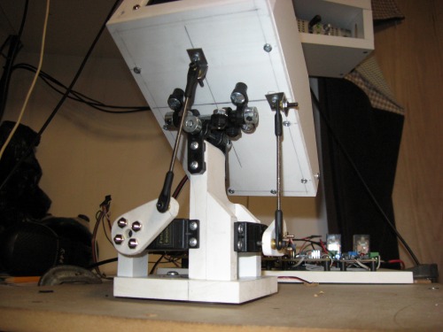
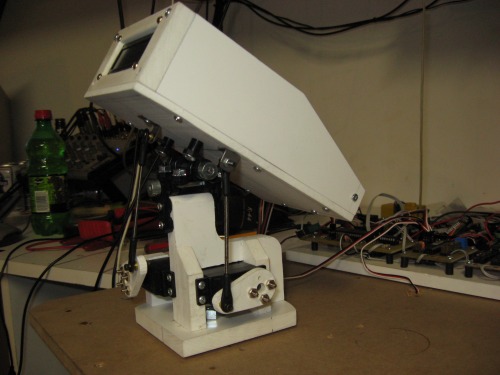
Also, I am working on a mock-up of the head design (I think I called it a brain in the video):
Basically, the head rests on a 2-axis pivot allowing for up, down and tilt as well as a combination of all three. This is just a test, I hope to clean the final one up quite a bit.
This is a companion discussion topic for the original entry at https://community.robotshop.com/robots/show/walter-1-4


