Update - took a few photos to magically transform this blog from a mere “schematic” to a fully fledged, utterly incomplete “robot”.
Like a few others here, I’m trying to optimise the functionality of the picaxe 08. My approach is a little different - that by brute force. Some people prefer a more elegant and resourceful style, but I find that stuff too fiddly. I’m calling this tombot, because it’s ultimately a present for a friends 7 year old. Called Tom.

This robot will navigate using the homebrew IR tx/rx, from oddbot:
which has a great range, and having the tx/rx spread apart like this and soldered snug against the perf board eliminates problems associated with lining up the two components.
The IR tx/rx is moutned on a servo, that will constatnly pan lef/right looking for things in it’s way, so it can run the other way.
It will also have a bumper switch for fuzzy and/or narrow things that the IR can’t pick up.
Abuut 2 minutes prior to writing up this post, I learned about using the tristate capability of the iO pins to get a third pin state for control of the motors - but, I’ve already etched the board, and I don’t really need the robot to be able to stop. Anyhow, nuumio promised he was about to do a tip/walktru on tristate operation in a few minutes.
At present, one pin controls one motor - high=fwd, low=bckwd. the signal from each pin is split into two, and half is inverted and fec into a L293. Why don’t I use servos? well, as oddbot says, because that’s cheating, and also, it’s more fun to do things the hard way…
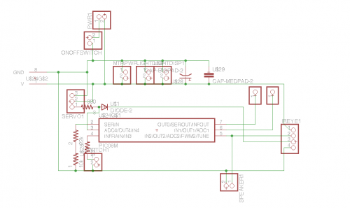
here’s a breakdown of the pin allocations
pin 1 - NA
pin 2 - NA
pin 3 (in/out/adc 4) motor 1
pin 4 (input 3) bumper
pin 5 (in/out/adc/speaker) speaker AND adc input (from IR pulse)
pin 6 (in/out/adc) motor 2
pin 7 (out 0) neck servo AND IR pulse out.
pin 8 NA
Yes, having the IR pulse out on the same pin as the servo causes problems - can cause problems - but re initialising the pin as aervo pin AFTER the pin is used to pulse the IR mitigates that problem pretty well. I couldn’t find a way to get pulsout to control the servos AND use a high pin command - I don’t know why, and I’m too scared to ask the crew at picaxe.org any more…

Here’s the circuit - apologies that it’s small. The two-pin headers are additional power outlets: Aside from the IR tx/rx, bumper switch and speaker, there’ll also be some neato flashy lights and things to spank it up a bit. pictures to follow for those who need them.
The diode seems handy for stopping the IR sensor from interfering with the servo and the adc signal is too weak to make the speaker do anything much - it’s only a pizo…

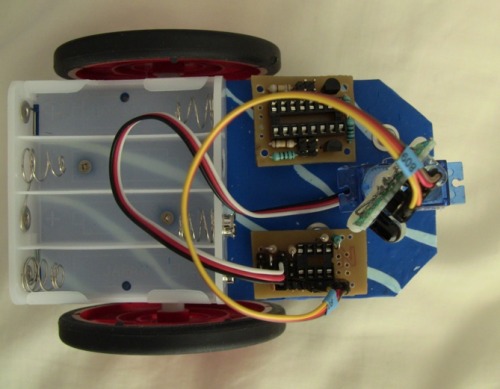
Here’s the layout from the top down. The brain-board of the 08M is the smaller one on the bottom, and the driver board is the big one on the top.
It’s not entirely clear why I am trying to so hard to have a small brain board, and then put a big fat driver board on there…
My question to any readers is - does anyone have any snappy little tones they’ve coded into a picaxe? when I say “little” - I really mean quite miniscule, my little arpeggios are a bit tame…
optimsing the 08 by sheer brute force
- Actuators / output devices: one servo, 2 geared motors, pizo speaker
- Control method: autonomous
- CPU: picaxe 08M
- Power source: 4.8 v
- Sensors / input devices: homebrew IR sensor, contact bumper switch
- Target environment: indoor
This is a companion discussion topic for the original entry at https://community.robotshop.com/robots/show/tombot

