i just got one of these: (sharp-gp1s36hez tilt sensor)
and im not sure about these schematics and i thought you could help me connect this to a picaxe 28x1 project boad and a 5 volt regulator!!!
it should be simple! :D
it got 2 outputs and that wil tell me if it si opright, side, other side or down
and its about 4x4x5(+pins) mm in real size
please help me, it would be best if you could make a wire-schematic showing pins on the project board and on the sensor and the resistors in between.
ps. when i get this done i will post this sensor in the LMR "components" thingy :D
EDIT: i got some advices but im still confused! im not good at understanding a schematic if it's on text
therefore i made two pictures of what i think you mean..
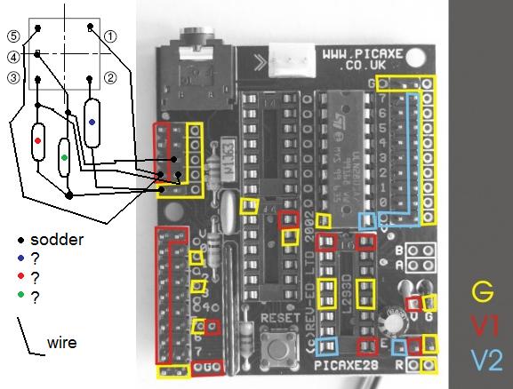
..but you still have to download these yourself and edit them (dont worry, i made them simple and easy for you to edit, unless you are color-blind)
other one:
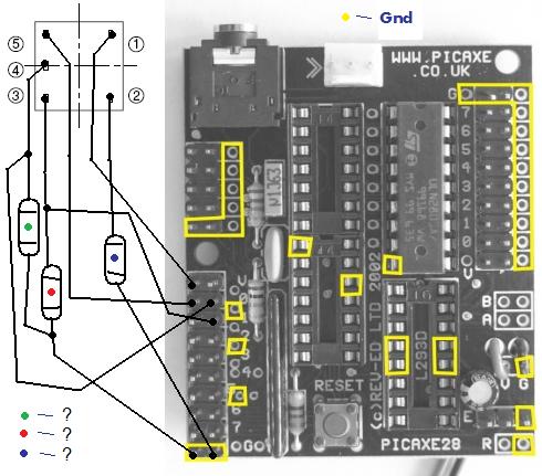
please download and edit! :) and i would like the analog version best(i'm running out of digital inputs, that im going to use for other stuff then this)
Ok, since you’re using the
Ok, since you’re using the project board I’ll assume you’ve got a 4.5V supply. All you need apart from the sensor and your PICAXE are 3 resistors: one to limit current going through the LED, and the other two will pull down the phototransistor outputs.
The LED has a typical voltage drop of 1.2V and happily runs at 20mA, which means we want a (4.5V-1.2V)/20mA=165Ω resistor, but anything close will do. Connect pin #1 to your 4.5V supply, and connect your ~165Ω resistor between pin #2 and ground.
Next are the two identical phototransistors, which each tolerate up to 20mA, and have a voltage drop of no more than 0.4V. 20mA per phototransistor is a bit of a waste, so we’ll use 5mA instead, which is mentioned in the characteristics data so we can assume it’s a good value. We don’t know what the minimum voltage drop is, so we’ll pretend it’s going to be zero in the worst case. The resistor we need is therefore 4.5V/5mA=900Ω, but once again you don’t have to be exact here, 1kΩ resistors for example are nice and common. Connect pin #5 to your 4.5V supply, and connect one ~900Ω resistor between pin #3 and ground, and the other between pin #4 and ground. Now connect pin #3 to one of your available digital input lines, and connect pin #4 to a separate input line. You can use one of your analog input lines here instead if you really need to, but the digital lines are less hassle and you’ve got twice as many of them.
Now all the hardware is done you just have to program it. Check out the ‘supplement’ diagram on page two of the datasheet: when an output is ‘ON’ you’ll get a high signal at the connected input on the PICAXE, and likewise you’ll get a low signal when the output is ‘OFF’.
thanks!!! :Dbut i use a 5
thanks!!! 
but i use a 5 volt regulator…
will that make a big difference in Ω?
and you say: "connect one ~900Ω resistor between pin #3 and ground, and the other between pin #4 and ground"
when you say the"the other" do you then just mean another ~900Ω??
Recheck calcs
LED calculations are correct, but should usually use a resistor slightly higher than calculated value, to account for battery charge or changes in voltage. So a minimum standard value of 180 ohms could be used to get close to the max 20 mA current for the LED. In the Electro-Optical characteristics section, both 5 mA and 10 mA are used for determinations, so an even larger value might be used to keep from overtaxing the LED. 10 mA would be suggested to ensure photo-transistor saturation, so going with 4.5 volts, (4.5-0.4)/0.01= 410 ohm, use a standard 470 ohm 10% resistor.
The phototransistor calcs are a bit off due the missed attribution of If from the LED charecteristics. The phototransistor collector current Ic in the specs is 55 uA minimum, up to 300 uA, but not into the mA range. Using the 4.5 volt supply again, (4.5-0.4)/0.000055= 74545 or 74 Kohm. This time since the resistor is used to ensure the widest possible voltage swing and not to limit current, I’d go down to the nearest standard value to a 68K 10% resistor. This value should allow the output between collector and resistor to swing from 0.4 volts when the transistor is on in saturation, to a 3.4 volt high when the transistor is mostly off, only allowing a 17 uA leakage current.
The LED tolerates a maximum
The LED tolerates a maximum of 50mA, like many IR LEDs, so you don’t need to worry about overtaxing it. A lower resistor value will make the LED brighter, which allows more current through the phototransistor, so unless you’re desperate to reduce your power consumption I’d aim for at least 10mA, or a (5V-1.2V)/10mA=380Ω resistor.
Robologist is right about the phototransistor current; although the phototransistors can run up to 20mA each that can only happen if they saturate, which can be quite difficult to acheive in a phototransistor.
Unfortunately the maximum voltage that a PIC Schmitt trigger input will read as ‘low’ is 0.2Vdd, or 0.2*5V=1V. If you use a 68kΩ resistor then @ 17uA ‘OFF’ current you’ll get 1.156V at the input, which is just inside the forbidden zone, where the results will be somewhat unpredictable. Similarly the minimum Schmitt trigger input for ‘high’ is 0.8Vdd, or 4V, which is just over the 3.74V you’ll get @ 55uA ‘ON’ current.
Since the 17uA maximum leakage current is something we can’t fix, I’d suggest using a slightly ~47kΩ lower resistor to keep the maximum ‘OFF’ voltage below 0.8V. If the LED current is a healthy 10mA then it’s unlikely the phototransistor output will fall below the 85uA ‘ON’ current needed to sustain an output voltage of 4V or more.
“and you say: “connect one ~900Ω resistor between pin #3 and ground, and the other between pin #4 and ground”
when you say the"the other” do you then just mean another ~900Ω??"
Yep, that’s what I meant, although replace 900 with 47k.
EDIT: Here’s a modified copy of your diagram -

WOW! thank you so much!!!
WOW! thank you so much!!!
so now this would be correct? (i mean the wires’s connection!)
Is there a reason why you
Is there a reason why you are using the Analog inputs rather than the regular Inputs?
yep!
i use all my servo-ports and therefore use some of my digital inputs as outputs for some leds, speaker and a laser, but i also use it to handle a LDR as input.
i only use one sharp-gp2d120 and still dont have any uses for the other analog inputs…
…any special reason you ask, or…? 
ohh… i also have to ask you
ohh…
i also have to ask you how to use the sensor with the analog!?
you see… i only know how to use the analog to handle sharp ir stuff
i would know how tom use it on the digital but im almost out of digital inputs and i need them for other stuff i plan
please…! please help me, by telling me how to use analog in programing editor! (by text exambles etc.)
I believe you would look at
I believe you would look at it to see if it has 5v or so (or whatever the voltage is going into the sensor). I do not know what kind of reading the analog gives you for 5v, but check to see if that pin = 5v and if so, then set a bit, else, reset that bit.
do you think i could just
do you think i could just debug and test some movements etc.??
to get some data, numbers…?
Sure. I do believe with
Sure. I do believe with that sensor, its on/off with the phototransistors. There might be a slight variation, but for the most part it will be around 5v.
What language are you doing
What language are you doing all your programming in? We can hook you up with some analog reading examples if we know.
Basically the input voltage will be 0.799V or less when the sensor is ‘OFF’ and 2.585V or more when the sensor is ‘ON’. If you read in your voltage and then compare it to, say, 1.692V (right in the middle) you can write a little function that goes like:
• Read in analog voltage.
• Subtract 1.692V from the input voltage reading.
• If the result was negative, the sensor must be ‘OFF’. Continue as normal.
• If the result was positive, the sensor must be ‘ON’. Go do something special.
The reason for asking is
The reason for asking is that we (Telelfox and I) have been answering based on a standard PIC input, whether TTL or Schmidtt trigger based, when it really doesn’t matter as much if an analog input is being used. I just noticed the analog use when glancing at the connection diagram presented.
Using the PICAxe readadc command, which gives a number between 0 and 255, you’d look for a low value when the phototransistor is off, probably something below 50. If the value is near 200 or better, the phototrans should be ON as the datasheet talks of, and can be used in a comparison statement, like a “IF ana-value > 200 THEN…”. The logic presented in the datasheet can then be used to estimate the orientation of the robot.
i use picaxe basic
i use picaxe basic
by the way… can i use a
by the way… can i use a 330Ω instead of 380Ω?
Sure, the resistor values
Sure, the resistor values are all approximate. 330Ω for the LED resistor will net you (5V-1.2V)/330Ω=11.5mA, which should be strong enough but still way below the 50mA limit.
and you are sure it’s 47k
and you are sure it’s 47k and NOT 4k7 or anything!?
???
Yep,
Yep, 47,000Ω.
4k7Ω/4.7kΩ/4700Ω would net you:
• ‘OFF’ voltage = 4700Ω17μA = 0.08V or less
• ‘ON’ voltage = 4700Ω55μA = 0.26V or more
Since you’re using the analog inputs you could use a higher value resistor quite easily, but a lower value resistor will decrease the voltage change when going from ‘ON’ to ‘OFF’ or vice versa.
luckyly i just found some
luckyly i just found some 47k in an old(broken) RC-remote


