

This robot comes in a kit from A-wit, the original name is BOL-bot (Board of Learning). http://www.c-stamp.com/CS710003.htm
The “brain” of the robot is a C Stamp 48-Pin Module and is coded in CW using MPLAB to write then build it, you then send the program to the robot through either a usb or serial cable.
The C Stamp module has 43 I/O pins, 12 ADC channels (10 bits), 2 DAC channels (10 bits) and has processor speed of 40 MHz. The micro controller is a PIC18F6520 and thanks to a voltage limiter build in to the C stamp it can run while being supplied 5 to 24 V DC .
The C Stamp it has several advantages over BASIC Stamp micro controllers. Some of these are more memory, more speed, floating point numbers support, unlimited program structure nesting, and function recursion.
When using the Development Board to program and test circuits the whole board can be supplied power either by a 9V battery (you can change the type of battery later on) or a by wall plug outputting 5 to 24 V DC. A big switch allows you to chose which power source you want to use and allows both the power supply and battery to be present on the board at the same time.
Here are a few more specs taken from the web page http://www.c-stamp.com/CS310000.htm
· Independent 1 A high current power (VHC) generated on board for servos or other components that require more current than what the C Stamp can provide in large projects
· No jumpers required for configuration
· Serial (DB-9) connector for C Stamp IC programming and serial communication during runtime
· C Stamp I/O pins, VIN, VHC, and GND connections brought adjacent to spacious full size 6.50" x 2.14" breadboard area
· Female 10-pin dual row connector for additional connections
· Four servo connectors pre-connected to VHC, GND, and C Stamp I/O pins for control
· RESET button with high tactile feedback
· START button with high tactile feedback
· START button can be used as a utility button during run time
· Additional utility button with high tactile feedback
· 8 utility green, high intensity, general purpose Light Emitting Diodes (LEDs) (great for debugging)
· C Stamp power indicator LED
· Documentation and Projects with Guides included
Here is a link to a Picasa web album that should be updated with the latest pictures http://picasaweb.google.com/vincentyegen1/PhotosOfTheChosenOne#
__________________________________________________________________________________________________
22/07/2009
This is my second robot, this time built from a kit. It was intended to teach me CW and a few other things about robotics during my 2 week session at TCNJ robotics camp.
The kit can be bought from http://www.c-stamp.com/robots.htm, the one given to us had an LDR, IR sensor and IR LED at first used for distance sensing, 2 big bumper switches and a Bluetooth module witch allows the robot to receive commands from programs from the PC either from the user or a visual recognition program such as Robo realm.
The robot is controlled by a C-stamp and a breadboard adapter (http://www.c-stamp.com/products.htm) witch is actually really good and it has nice features witch makes it quite fun.
It is now 10h07 and everybody is either plating Halo 3 or Halo 1 so working is a bit difficult and in my opinion is it is better to join in and have fun.
I will update this page with pictures (good quality ones thanks to Michael with my new camera), videos and info about the bot when the camp is over and I fly back home but if you have any questions feel free to ask.
BTW the name comes from my Halo pseudo (owned them except when Swine Flew was playing) and also because my robot seems to be self aware, long story...
__________________________________________________________________________________________________________________
UPDATE 23/07/2009
The first video is of my BOL-BOT aka TheChosenOne being controlled by me on the PC using Bluetooth.
It has a decent speed but the reaction to the turn commands are a bit slow because I had to insert loads of pauses to stop a charge building up when the servos switched direction witch would cause the C-Stamp to reset, and unlike Picaxe chips this one needs to be restarted manually by pushing 2 buttons on the board.
The bumper switches at the front are not connected to anything but they once were for a maze competition, same thing for the LDR at the front.
__________________________________________________________________________________________________________________
UPDATE 08/08/2009
Well today is a good day!
Many things happened;
First, since I came back this robot has been sitting idle on next to the computer, why? Because both CD players on my computer are broken so I have no way of installing MPLAB and CSTAMPQP (used to download the program to the C-Stamp. But thanks to some a few searches on google I found MPLAB, so I can know code. But what about downloading it? Well thanks to my USB key and a few useful copy and pastes before I left I also have the downloader and all the documentation I need.
If you look at the pictures on the picasa web album you might notice an LDR attached to the front of the robot. That was for a competition, navigating a maze, it was used to detect when the bot was pushing against a wall (it could sometimes get stuck that way) and tell it to reverse. The day of the competition that Idea failed because there were too many people around the maze so more light was reflecting in so the settings were thrown of. To fix this problem I decided to put a pushbutton on the front, and thanks to some digging in my parts box i found the perfect candidate, all it needed was a bit of sanding to fit perfectly.
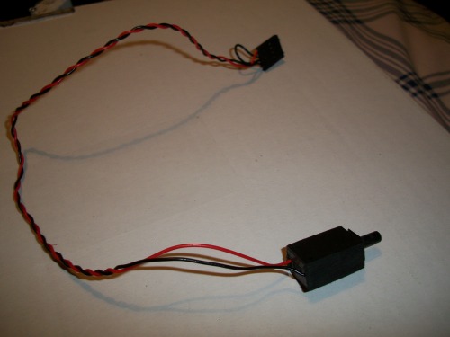
After a bit of sanding from a dremel if fit perfectly.
There is one more thing you will notice on the pictures that are up for know, on the breadboard there is a bunch of wires surrounding a odd liking chip. That is a bluetooth module (http://www.c-stamp.com/CS471000.htm) that allows me remote control the bot from a pc. I would like to keep that capability but it does take up loads of space on the breadboard and I would like to expand its capabilities, which means having to use breadboard. So i decided to build my on PCB using PCB Layout, which is great for beginners!
I still need to decide where I will mount it so that I can place mounting holes.
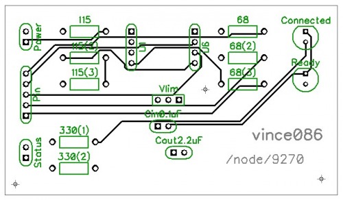
Here is what the top layer of the PCB will look like.
The “Ready” LED will be a small yellow one and the “Connected” one will be a small green one.
I will have the yellow one turn of once the Bluetooth connects so that it saves power.
__________________________________________________________________________________________________________________
UPDATE 16/08/2009
More PCBs coming!
One of the updates to TheChosenOne will involve a Picaxe 08M pushing the Start and Restart button, there is one problem is there is no access to the reset button located on pin 5, the start button is on pin 38 and that one has a female header going towards it. My solution?
Inspired by Arduino shields I designed this: (only the top traces are shown)
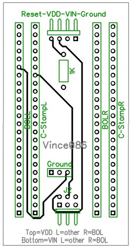
The top pins allow connection to pins 5,6,27,48 and the jumper at the bottom allows you to select to what pin 27 and 48 on the C-Stamp are connected to, the pins at the top of the PCB or to the BOL. (Pure genius if I do say so myself!)
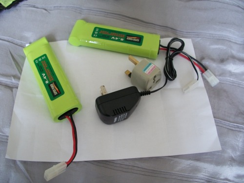
Another upgrade is 2 power sources to power the robot and replace the single 9V battery, I got two 8.4V 3800 mAh batteries and a charger for 32$ with shipping. I am also making another PCB to deal with the 8.4V and lower it to 5V using a switching voltage regulator (more efficient than normal voltage regulators which waste energy as heat). https://www.robotshop.com/letsmakerobots/node/10037
__________________________________________________________________________________________________________________
UPDATE 20/08/2009
Even more custom PCBs!
The latest PCB is not really out of necessity but more “just because I can”.
Since the C-Stamp shield allows me access to Pin 5 (used to reset the C-stamp when tied to ground though ground) and Pin 38 (start button) and it would allow me to fix one little problem that’s been annoying me lately; having to push the start button and reset button in sequence to get a program running. I can now fix that by using a Picaxe 08M to push both buttons in the write order when the 08M receive a signal from a digital input. At first I though of using a relay to connect the Pin 5 and 38 to ground, but if you know what a normal relay looks like you will understand why that option was a no go. To find a better way I posted a forum topic https://www.robotshop.com/letsmakerobots/node/10223 and got loads of replies, but it was one from ignoblegnome that saved the day. After writing a simple code for the Picaxe to set all its pins to LOW all I had to do was connect 2 jumper wire to pin 38 and to test it. And as expected it worked perfectly. The picture below is the top traces of yet another PCB that will make mounting and connecting everything much simpler and nicer.
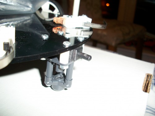
As you can also see in the main picture I have been playing around with the configuration of the 2 decks and the BOL. I think that the current arrangement is the best because it allows me easy access to the BOL and loads of space on the decks. In the current picture the BOL is being powered by a 7.2V battery from my rc car but it will soon be replaced by the 2 new ones I ordered.
__________________________________________________________________________________________________________________
UPDATE 27/08/2009
My batteries have arrived!!
It took me some time to find the write batteries on ebay but it paid off !
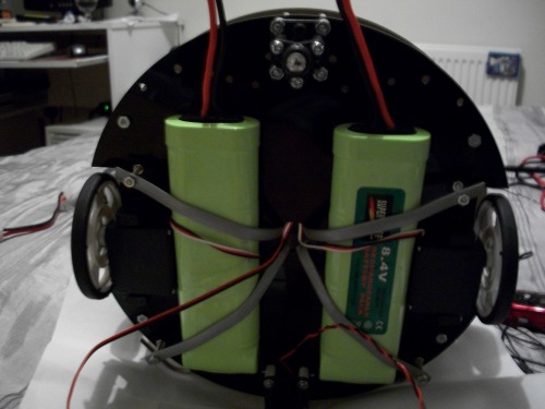
It didn’t take me that long to mount them on the bottom of the BOL-bot, there is a video on my youtube account explaining how I did it, the link to my account is at the top under “URL to more information” in the box at the top right of the page.
I decided to mount both batteries on the bottom of the chassis like that I save much more space for other stuff. Under is a picture of how they look attached to the bottom.
__________________________________________________________________________________________________________________
UPDATE 30/08/2009
By now you have probably noticed that all my work concerning this bot is construction and not one bit of programming. That is because both CD players on my pc haven’t been working lately (most likely a virus) so I can’t install all MPLAB and the programs that need to go with it to program the C-Stamp. I dont know when or how I will fix this but I will have to find a solution if not I wont be able to program at all and if that’s the case this robot is nothing more than an expensive paperweight. I have tried to install it on my external HDD from another computer but that didn’t work. I will try 1 or 2 more techniques and hopefully one of them will work if not I wont be able to program it.
__________________________________________________________________________________________________________________
UPDATE 25/10/2009
My Custom PCBs have arrived!
Had to wait a bit but it was totally worth it!
Here is the link to my blog with all the details: https://www.robotshop.com/letsmakerobots/node/11451
And here is the link to a Picasa web album with more pictures: http://picasaweb.google.com/vincentyegen1/CustomPCBs?authkey=Gv1sRgCJSv9qGJ-Z225AE#
One of the PCBs I ordered had a mistake in it that I didn’t correct before sending it off to be made, well my mistake, at least all the other ones seem perfectly fine.
It will be some time before I get them all doing what I want to ( need to program the thing).
The circuit that handles the power is ready but I haven’t tested it yet, still afraid I could fry something and that would be a major setback.
RC via Bluetooth, avoids obsticals
- Actuators / output devices: 2 continues rotating servos
- Control method: Full autonomous, Remote controlled
- CPU: C-stamp
- Power source: Two 8.4V 3800mAh battery packs
- Programming language: CW
- Sensors / input devices: IR, bumper switches, LDR, Bluetooth
- Target environment: indoor on smooth surfaces
This is a companion discussion topic for the original entry at https://community.robotshop.com/robots/show/thechosenone