

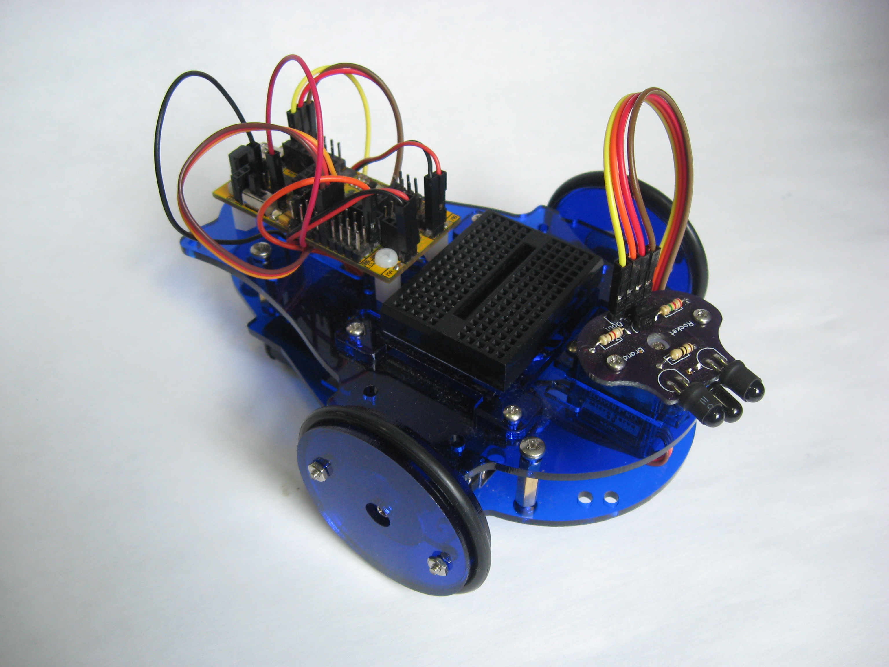
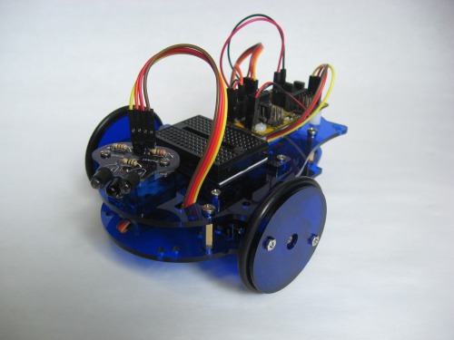
The LMR Start Here version of the Tadpole robot is a great way to get your feet wet in the world of robot building. It is a nice, simple platform, requires only one tool for assembly and no soldering. It can be a very simple, basic robot to learn the fundamentals, or, as you can see in the promo video, be configured to be as complex as you would like. Along the way, you will learn all the basics of robot building --These basics will translate easily to any robot you might build in the future.
Rocket Brand Studios Main Site
Tadpole LMR Page (Get one Here)
Tutorials Main Page
For every Tadpole LMR, Rocket Brand Studios will make a donation to LMR to support the community that supports you!
Welcome,
Let's see if we can make a robot. It won't be that hard, you can do it, you are a very talented person.
These instructions are for the Tadpole Start Here Robot kit. We will assemble the robot then go through a series of tutorials to learn how each component of your bot works. The goal here is to get a working robot in your hands as quickly as we can so we are going to keep things to “just what you need to know” for now. In the end, we will have the basics down and a working autonomous robot. From there, you are only limited by your programming skills. As you learn more code, your robot gets cooler, its that simple.
If you are building your own robot and not using the Tadpole kit, follow along anyway --The basics we will cover here will be the same for just about any beginner’s robot. Reading inputs, controlling motors, moving servos, etc. will be universal no matter how your bot is built.
We’ll get to our assembly in just one wee second, but first, let’s cover just a few basic concepts and pointers.
The whole “robotics thing” is simply taking a big, complicated thing and breaking it down into smaller steps. This is true if you are a newbie or building the Mars Rover. Small steps, built on each other, to make a complex thing. You must learn these “steps” in order. --You can’t make a maze-solving robot if you can’t make your motors go...
Google is your friend. You should google everything --commands, error messages, when in doubt, google it. There is a joke in the robot world, “RTFM” Read The F[antastic] Manual. Its a snarky thing to say to folks, yes, but it is the truth. Every answer you could ever need is in a manual or datasheet somewhere. -You just gotta get good at looking. Google everything.
The very worst thing you can ever do at Let’s Make Robots is to ask a easily Googleable question in the forums.
Ok, Lets Make a Robot.
The assembly instructions found below can be downloaded (in Power Point format) here.
Go directly to the Assembly Blog Here
(Or by clicking picture below)

We can move on to downloading and installing the few things we are going to need to program our little bot…
Install the Arduino software, USB driver and Micro Magician Library
Download the Arduino software from here I suggest Arduino 023 and would not suggest any of the newer 1.0+ versions.
Download and install the usb driver from here.
We are using the Micro Magician board, install its library (How do I do this?)
Plug in your board with via USB and determine your com port number by going to Start–>(right click on computer)–>Manage–>Device Manager–>Com Ports. There you should see your Arduino board and its corresponding com port number (you will need this later)
Download the zip file of all the example code from here.
Alrighty, lets see if we can explain the above a bit more in-depth…
You will need the Arduino software to program your bot. This is sometimes called an “IDE” and is where you will write your code and how you will zap this code into your bot.
The USB driver is needed to allow your computer to talk to the “USB chip” on the MicroM board. There is no trick here, installing this driver will be as painful as installing any driver on a Windows machine and there is no magic bullet. As with every Windows driver install, just keep trying, you computer will play nice eventually.
The MicroM board includes a “library” to operate properly. A library is just a chunk of code that is sorta “hidden away” from you and supplements your code. Typically, they are used to perform specific tasks (and usually complicated ones). In our case, the MicroM library takes care of the code needed to run our motors and read the couple sensors on our board. When you write your code, you will only need super-simple, straight-forward commands to control these devises.
Where is my “com port” --and what IS a “com port”? Ok, when we plug in our robot brain to the computer via USB, the computer will recognize this board as a “serial port”. “Serial” is simply a form of communication between electronic-y stuff. This connection, is called a “port” i.e. “communications port” and conveniently, they are numbered for us. We will need to know the com port number for your particular board. Here’s where to find it:
Click “Start”, then right-click on “Computer”. Click on “manage” and then "Device Manager"
From there, you will see “com ports” and if you expand it, you should see your Arduino board plugged in (you should make note of the number). If you don’t, you should probably go another round with the USB driver install (or realize that you forgot to plug in the board to the USB!).
If you would like to hear all of the above straight from the horse’s mouth, or if you are a Mac or Linux user, you may click one of the links below to go to directly to the Arduino website for another explaination of the above.
Arduino Install with Windows
Arduino Install with Apples
Arduino Install with Penguins
Can we make my robot do something already? Sheesh!
(Yes, we can)
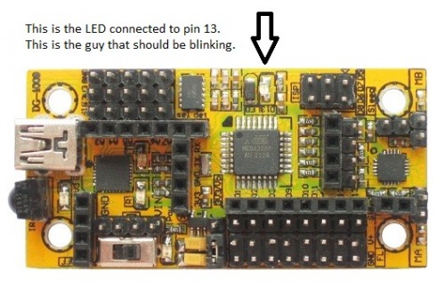
The tutorials start with a basic blink. This is where every robot builder starts. This is the “Hello World” of the robot building business. For this first tutorial, you won’t need anything plugged into your board except for the USB (you won’t even need batteries in the battery holder). If you have already plugged stuff in, that’s fine too.

The first blink tutorial is actually part of the Arduino software itself. Notice the caption below video --it will tell you where to find the example. From there, the rest of the examples reside in a handy zip file. Download it and unzip, there you will find example code for all the following tutorials. Each example is lettered (A…B…C…D…) and should be followed in order.
The “Basic Blink” tutorial goes with “Blink” found in the Arduino software.
Go to: File–>Examples–>Basics–>Blink
Are we blinking?
Hey, super-duper congrats if you are indeed blinking. I can assure you that you have gotten past the “worst of it” (installs etc) and everything from here-on-out should be a lot easier. You there, with your little blinking LED, is a really big deal --you should be wicked proud of yourself.
We can now move on to the meat-and-potatoes of the tutorials and some stuff that is just a wee bit more interesting than just a blinking LED.
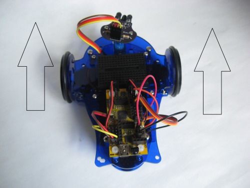
We move on now to getting our motors going straight. (Woo Hoo!)
Motors:

There is a very good chance that our motors may be plugged in incorrectly
(and its nothing you did wrong)...
The tadpole motors are run off of a "motor driver chip". This is because a microController cannot handle the large amounts of power that the motors will draw. Our robot brain will send a signal to our motor driver and thus, the motor driver will "turn on" our motors. --Even better, the MicroM library we installed will take care of all the difficult coding for us as well.
In this tutorial, we will determine if the left motor is indeed left and if the right motor is indeed right. Next, we will determine that both motors are going in the forward direction when we tell them to do so.
Which Motor is Which Tutorial Video Here
This video goes with code examples:
(A) Which is the left motor
(B) Which is the right motor
Got the motors spinning, huh?
Fantastic. Let’s move on and see if we can get them both to go at a decent speed --and the same speed.
Motor Speed and “Go Straight”:
Why do identical motors run at different speeds?
Well, because they are not identical! Put simply, even “identical” motors will run at different speeds (at least a little bit). In addition, motors tend to run better in one direction that the other. Because our motors are mirror images of each other (one left and one right), one motor is always running in “reverse” because it is on the “other side” of the robot. Any way you look at this, it is unlikely that your robot will drive perfectly straight on the first shot. In this tutorial, we will learn how to control the speed of our motors and get them to be equal (or pretty darn close to equal).
Motor Speed Tutorial Video Here
This video tutorial goes with code example:
© Motor Speed and Go Straight
How’d we do?
Did you get the little guy going straight and at a good, kinda-slow speed? Super. It may be a good idea to make note of these “speed numbers” in your notebook as you will probably refer to them each time your sit down to write code.
Ok, let’s play with a servo.
Controlling our Servo:
Wait a second… You said we can’t plug motors directly into our microController…
Yes, I did say that. I also mentioned the use of a “motor driver chip” when we did some of our motor tutorials. Conveniently, servos just-so-happen to bring their own motor drivers with them. Let’s get right into it…
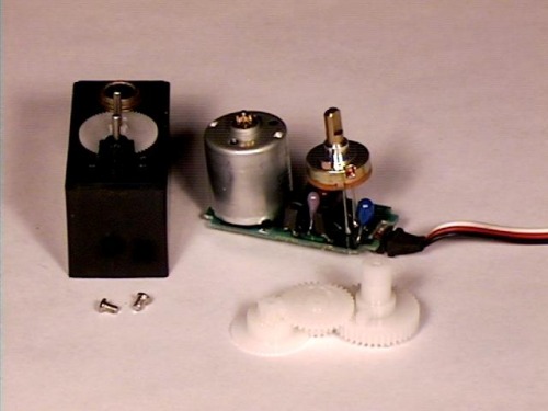
A servo is a little device containing a motor, gearing, position sensor, brain and motor driver all in one tiny package. Typically, they are used in R/C model airplanes and cars. They are not motors in the traditional sense and (except for a few specialty servos) then can not make a full revolution. They can however, rotate to very specific positions when we tell them to do so. In this case, we will use our servo to “sweep” our sensor. --To allow the robot to “look” from side to side.
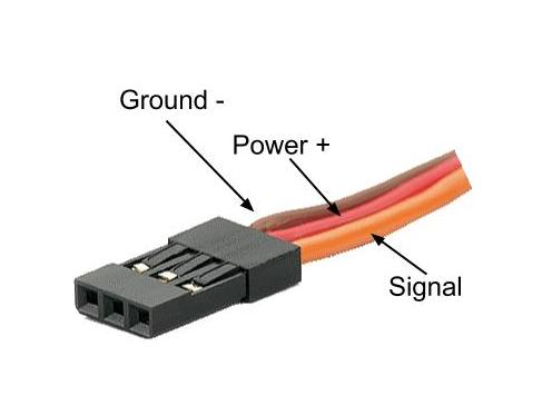
A servo typically has 3 wires coming from it. Power and ground are usually red/orange and brown/black. The third wire is normally a light color, white or yellow. The two “power wires” power the servo (directly from the battery, not from the microController’s pins). The “signal wire” requires only a “data level” signal and is connected to one of the microController’s output pins. Because we supply the servo with its own battery power, and the microController only has to output a very low-level signal to the servo via its “signal wire”, there is no fear of smoking our microController by running too much current through it.
When we tell our servo to go to a given position, the servo reads its internal position sensor (to know where it is currently) then figures out how to get to where we told it to go. It then commands its internal motor driver to turn on the motor to go to the new position. Once there, the motor turns off. As the servo sits in this position, it constantly keeps an eye on its current position and maintains it. I.e. if you tried to move the servo by hand, and it is receiving a signal from the microController to stay in a given position, it will indeed resist you and stay where it is. --that is of course, until you turn it so hard you strip the gears…
The system that Arduino uses to control servos happens to be built right in to the Arduino software. Running servos is something very “native” to robot brains --they are sorta designed to do it. Servo commands already exist in the world of Arduino and are quite easy to work with.
In this tutorial, we will learn how to make our servo go to a given position. The first position we will go to is centered. --When we assembled our robot, we installed the sensor on top of our servo, but we had no way of knowing if the servo itself was centered. Now, we will center our servo, remove the sensor, and reinstall it. --This time with the servo centered (and thus, the sensor centered). This way, the robot will know where the servo is pointing and thus, which way the robot is “looking”.
In addition to simply putting our servo in one position, we will also learn what a “for loop” is and how we can use these for-loops to “sweep” our servo from one side to the other. For-loops are incredibly important and you will use them for all kinds of stuff in the future. Using them for moving servos is a great way to learn how they work. Later we will add code to read our sensor during this “sweep”.
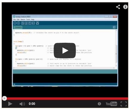
Sweep our servo tutorial video here.
This tutorial uses the “Sweep” example in the Arduino Software
You can find it by going to:
File–>Examples–>Servo–>Sweep
Did we get our servo sweeping?
Fantastic. Let’s move on to our sensor and see if we can get a reading from it.
Reading our Sensor:
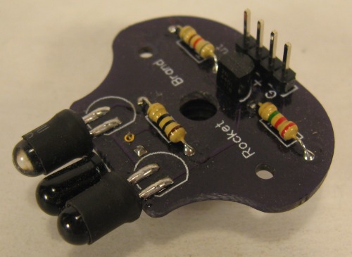
We have a sensor on our little bot to detect obstacles. More specifically, we are sensing distance to an object more than anything else. Let’s see if we can figure out how this all works…
Your sensor consists of a few things, IR LED’s, an IR sensor and a transistor to turn the LED’s on and off. Remember motors drawing too much power? Well, our LED’s can draw too much power as well --At least the high-power LED’s on the sensor board can. We use a transistor, which is like a little switch (or like a super-simple motor driver) to turn our LED’s on and off via a low-level signal from the microController. We don’t just leave the LEDs on constantly because we don’t want to deplete the batteries too quickly and also, the ability of the microController to controller to turn these LED’s on and off, will allow us to do some fancier things via code in the future and thus, increase the precision of our sensor. For now, however, we will be keeping things very simple.
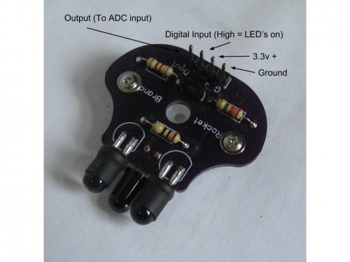
We need two kinds of pins to control and read our sensor. We use a digital pin (one that can be either on or off (high or low)) to control the transistor and thus, LEDs. We use an analog pin (ADC pin) to read the signal coming from our sensor. Analog inputs can read a varying voltage level and will spit-out a corresponding number from a given “scale” of numbers. In our case, the voltage coming from the sensor will rise as an object gets closer and fall when it moves further away. The Arduino will read this analog signal, give us that corresponding number, and we will use this number to determine a “danger threshold”. This “threshold” is the point at which we can say, “we are too close to an object, we should change direction to avoid it”.
The operation of your sensor is quite simple: The IR leds shine forward and, when an object is present, gets reflected back. If the object is close, more light is reflected. The IR sensor reacts to this changing level of light and allows more or less current to run through depending on this light level. This changing power level coming out of your sensor is what is read by the analog pin of the Arduino (as described above).
Because this sensor is a very basic one, and because it uses IR light, problems can occur based on ambient light levels. Put simply, your little bot is probably not going to work very well in direct sunlight, and may get a bit temperamental depending on how bright your regular house lights are. During this tutorial, we will read our sensor and at that time you can experiment a bit with how different amounts of ambient light affect your robot.
In this tutorial we will read our sensor, learn how to send data back to the computer so we can see it, and then add this code to our “servo sweep” code. Let’s get right into it…
Read our sensor tutorial video here:
This video goes with example code:
D_Tadpole_LMR_Read_our_Sensor
Got some good readings?
Remember to keep track of the numbers you found during your experimentation, you will need them in the next step when we put all of this together.
Hey hey, let’s get this little bot going by itself!
This final step is actually going to be pretty easy. You have already learned all the things you will need here, we just gotta put them together. The basic autonomous routine is pretty simple and goes something like this:
Sweep the sensor back and forth
Take readings at regular intervals
If a reading is closer than a “too close” threshold, then we must turn away
If we are looking left when something is too close, then turn right (or vice-versa)
-
If nothing is too close, just drive forward
This is about as simple as an autonomous routine can be, and it should be said that many improvements can (and should!) be made, but for now, this simple example will give you the best shot at getting a working robot without too much hair-pulling…
In this tutorial, we will add our “sensor reading” routine to our “servo sweeping” routine. Also, we will add the code that will control our motors based on our sensor readings and position of the servo. Again, you already know the vast majority of what is contained the the autonomous code, we are simply putting all those pieces together here.
Autonomous tutorial video here
This video goes with code example:
E_Tadpole_LMR_Auto
How did we do? Did we get our little bot driving around by itself? Pretty cool, huh? Congrats.
Well, that should get you started. Take what you have learned here and make your robot even cooler! Google, search blogs, watch Youtube. Get excited and build stuff! Remember, your robot is only as cool as your programming skills… …The more you learn and grow, the more awesome your robot can be!
You can do it, you are a very talented person.