[/font][/size][size=2][font=Arial]I swapped the DAT and ATT pins in the code from 6 for DAT and 8 for ATT to 8 for DAT and 6 for ATT, but the controller did not work after uploading the code. After changing it back, it worked again. Is this what you meant when asking to swap DAT/ATT from 6/8?[/font][/size]
[size=2][font=Arial][/font][/size][size=2][font=Arial]
[/font][/size][size=2][font=Arial]Still got a corrupted output after retesting.[/font][/size]
[size=2][font=Arial][/font][/size][size=2][font=Arial]
[size=2][font=Arial][highlight=#ffffff]If using the default SoftwareSerial example from the Arduino libraries, you should have those connected to pins 10/11, not 0/1. That maybe be causing some of the issues with the garbled test output.[/highlight][/size][/font][/size][size=2][font=Arial]I realized this yesterday and changed it. After changing it yesterday, I got the correct results from the BB before pressing start.[/font][/size]
[size=2][font=Arial][/font][/size][size=2][font=Arial]
[/font][/size][size=2][font=Arial]Already did that, but checked it again and re-uploaded it. Still not working after pressing start.[/font][/size]
[size=2][font=Arial][/font][/size][size=2][font=Arial]
[/font][/size][size=2][font=Arial]No other modifications were made. To be sure, I re-downloaded the programs from GitHub and just changed the pin numbers. Still doesn’t work after pressing start.[/font][/size]
[size=2][font=Arial][/font][/size][size=2][font=Arial][/font][/size]
To ensure that I you fully understand my setup, below is another updated photo.
I tried all the various configurations of the PS2 pins that I was able to find. Below are descriptions of each of the configurations I tried.
]The setup shown in this image with the code kept the same/:m] ]The setup shown in this image with the code’s pin numbers for ATT and DAT switched/:m] ]The setup shown in this image with the code kept the same and the ATT and DAT pins switched/:m] ]The setup described in 2, but the code’s pin numbers for ATT and DAT switched/:m] ]The setup shown in this image with the code kept the same/:m] ]The setup shown in this image with the code’s pin numbers for ATT and DAT switched/:m]
Only two setups resulted in the speaker playing stuff, number 1 and number 6, the other setups resulted in nothing happening after pressing buttons on the PS2 controller.
I have, therefore, eliminated the possibility of an incorrect setup with the PS2 controller.
Thank you very much for your patience and all the tests.
At this point, we ran out of potential ideas on what is causing the issue with the garbled output.
It does seem very likely that there is something wrong with your BotBoarduino.
The only other thing we can think of that could be causing an issue would be faulty libraries or Arduino installation.
You may want to make one last try with a fresh install of the Arduino IDE (1.8.5 at the time of writing) and temporarily rename your “libraries” folder found in your documents’ folder.
Then, create a replacement folder and place in it only the extracted quad libraries (those from the ZIP found here) and nothing else. Modify the PS2 and RX/TX pins as needed in the config and upload that.
If this still does not work, please reply to your ticket #454124 (or open a new one). In the reply, add a link to this post and request an RMA for the RB-Onl-23 (the BotBoarduino).
Again, we apologize for all the testing but due to the complexity of the platform it is difficult to identify such issues easily/quickly.
Hello,
I have received the new BotBoarduino and tested it. Unfortunately, I still receive the same results- the data is fine until the Start button is pressed and it becomes garbled.
In order to better troubleshoot the system, I decided to purchase an oscilloscope and logic analyzer. I hooked up the logic analyzer as shown in this image and collected data from all the various pins on the PS2. I did this to determine if the problem is from the PS2 and not the firmware or wiring. After looking at the data and comparing it to other PS2’s timing diagrams I found on the internet, I determined that the data is normal.
Therefore, because the PS2 is functioning properly, and replacing the BB did not fix the problem, I know that the issue is either due to improper wiring or faulty firmware.
Because you said that my wiring is fine, I assume that my wiring is not the source of the problem.
Moreover, you stated that the code worked on your BB, which means that the firmware is also likely not the issue.
Do you have any additional ideas on why the code is not operating as expected? It is very strange that individual tests of each part seem to work, but the system as a whole does not.
Since the setup is easily achieved and working in a few minutes, the only real possibilities for the cause of this issue are as follows:
]Wiring is indeed faulty somewhere but not visible in pictures (loose connection, damaged, intermittent wiring, etc.)/:m] ]Other damages to boards that was not noticed. It should be noted that in many of your pictures you have boards (that are not ESD safe) laying on carpet (which is known for keeping large static charges). It follows that this could very likely damage or destroy one of more components on the boards. This can bring them into undefined states where things may or may not work or may work in an unpredictable fashion. Exposure to ESD (even when not powered) can easily damage electronics boards./:m] ]Arduino IDE environment issues. It is possible that the way you are setup compiles the code wrong or with the wrong parts (the Arduino environment tries to be helpful which sometimes that causes it to use the wrong libraries or other unintended consequences)./:m]
That would be our best guesses at what might be wrong. At this point though, we’ve pretty much covered all we can concerning your setup troubleshooting-wise (at least remotely).
If you still get the exact same behavior as before swapping the BotBoarduino with the new one, we strongly recommend to examine anything that you have not checked/changed yet and verify that one by one methodically (i.e.: write a list down of all the components and test them individually and in circuit). Since you have a logic analyzer available, you should be able to test most connects very easily now.
How do I ensure that Arduino IDE is compiling the correct code? Is there a way to manually select the libraries to ensure that the proper components are included?
What components would I check? I don’t believe that there are too many connections and components for which I can test.
Moreover, what waveforms should I expect when hooking up the probes to all your recommended components? Are there any resources that you can send me that would direct my work?
Finally, something just came to my mind that I believe might be worth mentioning. When I compile the code in Arduino there are numerous warnings; below is a screenshot of the warnings that appear. Do you have the same warnings when you compile the sketch?
The simplest way is to do the following steps - which is what I do before anytime I test something for someone having issues:
]If not already at the newest Arduino IDE version (1.8.5 at time of writing), I uninstall the IDE./:m] ]Rename the Documents/Arduino folder to something else [path will prob. be slightly different on OSX/Linux]./:m] ]If the IDE was uninstalled, re-install it./:m] ]Get a fresh copy of the code from GitHub./:m] ]Extract all files and place fresh copies of the libraries in the new (and empty) Documents/Arduino/libraries folder./:m] ]Open the code in the IDE./:m] ]Edit the Preferences and set Verbose Compilation to checked./:m] ]Compile the code and check the verbose output./:m]
Since you are having issues with the output coming out of the BotBoarduino > SSC-32U, that would be the first set of signals to check. The “waveforms” in this case would be UART signals, so you’ll need to decode them appropriately. Your logic analyzer software should have the required parts for that.
That does not seem right. See the steps above.
Please find attached a copy of my compiler (verbose) output with a fresh Arduino install and only the QUAD libraries in my Documents/Arduino/libraries folder. 2018-07-24 - verbose compilation console output.txt (42.4 KB)
I followed these steps exactly, except that I changed the Tx and Rx pins in the config file after getting a fresh copy of the libraries. Below is my verbose output. After comparing my output with your output, the only discrepancies I found were some lines that stated that Arduino was using some “cached library dependencies” for some files; would this be a problem? Finally, when I compiled the code, it didn’t give any warnings. output.txt (14.4 KB)
When I hooked everything back up and looked at the output using my Arduino Uno, I still got the same output.
To ensure that the issue is not with the Arduino I am using, I decided to use my old BotBoarduino in place of the Arduino Uno by uploading the Software Serial code to the BB and looking at the output. I got the exact same results when I did this- the output is fine until I press the start button. This shows that the strange output problem is not with my Arduino Uno.
Thanks for the output example. I’ve recompiled mine to obtain a more similar output (where parts are pre-compiled) and accounting for path differences, here are the differences that are left:
Aside from different paths for the actual .INO file (yours seems to be in the libraries folder, which it shouldn’t normally be), there seem to be only one other significant set of differences (see image 2, bottom):
The FLASH and RAM size are different. FLASH on my compilation is 86 bytes larger and RAM use is actually 32 bytes smaller. This would seem to indicate your Arduino setup is compiling to something different than mine. A slightly different arrangement of the libraries (complete fresh) gave me 24430 bytes for the FLASH size.
Here is a copy of the code (and settings) we used and the compiled version of it. Could you please use avrdude to upload this hex file to your BotBoarduino? 2018-04-24 - Quad issue.zip (113 KB)
Sincerely,
I hooked up my oscilloscope to the Tx and Rx pins of the BB. Here is a video of my results.
As you can see, the data changes by becoming more rapid and less steady after pressing the start button.
Would this explain the garbled output after pressing the start button?
Moreover, because the data speed increases after the PS2 is used, could it be the clock speed or a timing issue on the PS2 that causes the garbled data?
Well, one reason that would explain garbled output would be the baud rate switching to a different one when you press start. Of course, that does not make much sense since the code does not seem to do that anywhere.
That being said, since it is using a SoftwareSerial interface (and library), though, it may be having other timing issues making its output garbled.
Therefore, a logical conclusion would be that your compiled version of the code experiences timing issues when outputting through the software serial interface.
A possible test would be to have the output come from the BotBoarduino’s hardware serial interface instead (in the settings .h file there are options to change from software serial to hardware serial).
This may be worth a try.
Also, you may want to give a go at the compiled go linked above.
Sincerely,
P.-S.: Please note that the PS2 CLK is driven by the BotBoarduino and that the TX/RX output is constant, whether or not the PS2 is connected or being read. In theory, the two are independent of each other.
How do I use your compiled code using avrdude? After looking around and trying to install it from here, I was unable to locate the proper installation for my system (Windows 7, 64 bit).
avrdude is the application (command line based) used by the Arduino IDE to upload compiled code to the Arduino board.
You can simply enable “verbose upload” and you’ll see the calls being made to avrdude from the Arduino IDE.
You can also find steps online about how to use it manually.
After uploading your compiled code using XLoader (avrdude wasn’t functioning properly), the code works! The robot is moving and I am getting proper output from the Arduino! This would, therefore, indicate that the issue was indeed a compilation problem. Therefore, how do I set up my Arduino IDE so that it properly compiles the code on my system?
Finally, because I never calibrated my Servos, the robot didn’t walk as it should. After looking around, I discovered that you can calibrate the Servos using your Servo Sequencer Utility, but the values would only be saved on the utility itself, and not the robot.
Therefore, because I am unable to calibrate the Servos in this manner, how would I calibrate the Servo positions for use in this code?
Thanks again for all of your wonderful help. I greatly appreciate all the time and effort you have put into supporting me.
Well, when it quacks like duck …] I’m quite glad we could identify some part of the issue you were having.
As mentioned before here, those are the steps to be followed. Obviously, something is still wrong after you followed them. My best recommendation would be to uninstall the Arduino IDE from your computer and then proceed to manually remove any other files left (in your root C: drive, in Program Files/Program Files (x86), in Users[User Account]\AppData and in Users[User Account]\Documents [and any other places you can find any]). Once that is completed, do the following:
]Install the Arduino IDE (from here)/:m] ]Download the libraries again (from here) and the code (from here; direct link to QuadC_PS2_SSC32.ino and Hex_Cfg.h [right-click and select [b]Save As…)/:m] ]Extract the content of the libraries to your *Documents\Arduino\libraries* folder./:m] ]In *Documents\Arduino* create a folder named QuadC_PS2_SSC32 and move the two files (QuadC_PS2_SSC32.ino and Hex_Cfg.h) into it./:m] ]Double-click the QuadC_PS2_SSC32.ino to start the the Arduino IDE and see the code. Change pins PS2 and TX/RX as needed for your setup. Recommended is CLK=9/DAT=8/CMD=7/SEL=6 and OUT/IN = 12/13./:m]
While checking out what to do with the Arduino IDE environment, I noticed something else. It does seem like the only potential difference would be the #define concerning binary mode. In the code that is in the libraries’ ZIP, it is activated (which may explain why the output is “garbled”). In the one by itself in the GitHub (linked above) and the one I used, the binary mode is not active (commented out using //). This is most likely the reason you are having the issue! Oh well…
There’s a few ways you can do this. Since you have a SSC-32U you could:
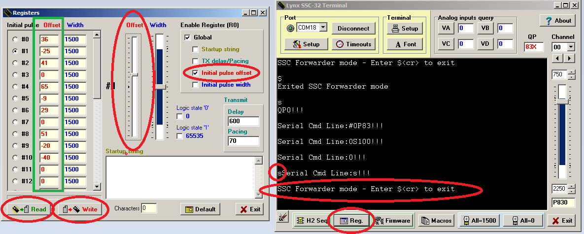
]Use Lynxterm. Disconnect the TX/RX/GND wires from the BotBoarduino to the SSC-32 and place back the jumpers. Power the SSC-32 through VS1 (blue PWR LED should be on). Connect the SSC-32 to your computer by USB via a RS232<>USB adapter. Open Lynxterm and follow the steps below to calibrate each joint:
(do note the process starts at step #0 (All=1500). Do be careful as pressing that button will move all servomotors to their center position instantly!/:m] ]Use the BotBoarduino as a passthrough. Since RS232<>USB are not always available easily and the BotBoarduino has a USB port, it can be used as a UART TTL<>USB adapter. This does not require any new code as it is part of the default Phoenix code. With the robot fully powered, connect the BotBoarduino by USB to your computer. In Lynxterm, connect to that new port at a baud rate of either 38400 or 57600. Press the RESET button on the BotBoarduino. Within a few seconds, you should see the menu appear in the black text box. Simply type the letter for the SSC-32 forwarder mode (should be S) and wait a few seconds for it to activate. You can then calibrate your robot as if you were connected to the SSC-32 directly (see step 1 and image below).
Well, no problem at all! We know this platform works well (it has been for a while) and wanted to make sure your instance of it worked, too! As a benefit, all the troubleshooting done for your kit is now freely available to everyone else.
I have another strange dilemma.
When I try to connect to Lynxterm, it says that it cannot find the SSC-32 card and it does not print out the version after entering VER. However, when I click All=1500, the Servos move in response. I am also able to use RealTerm to connect to the board and type VER with a proper response.
I have the baud rate set correctly and all the other settings align with the image you sent.
Do you know what might be causing the issue?
UPDATE: I tried a different USB to Serial adapter and I was able to properly connect to my SSC.


