

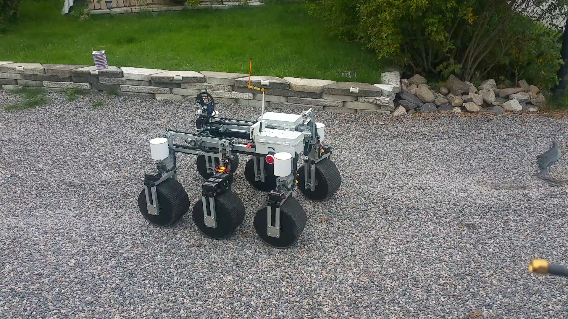
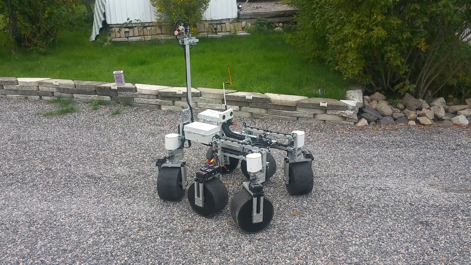
This is my new project Squidscout.
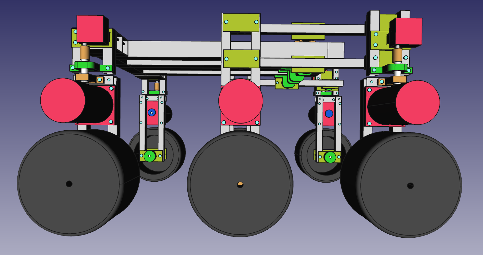
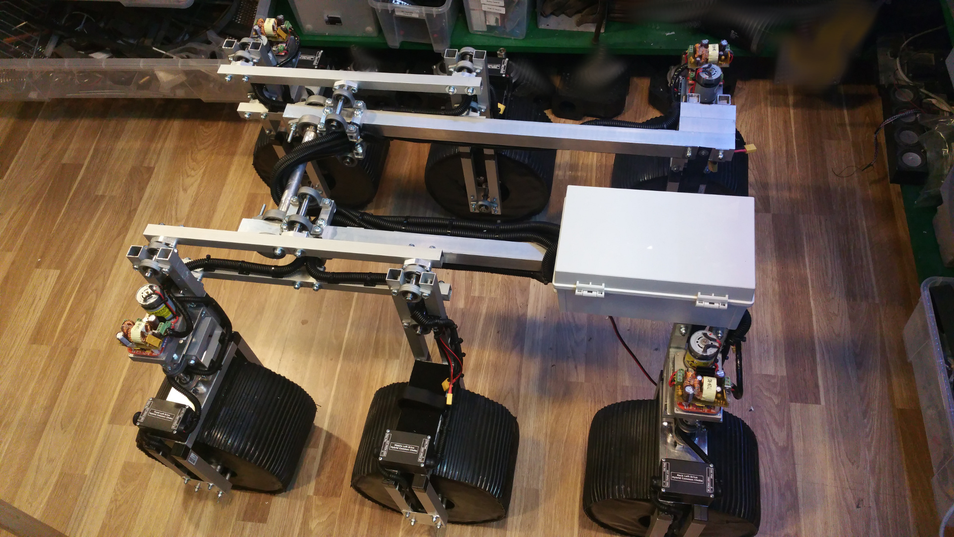
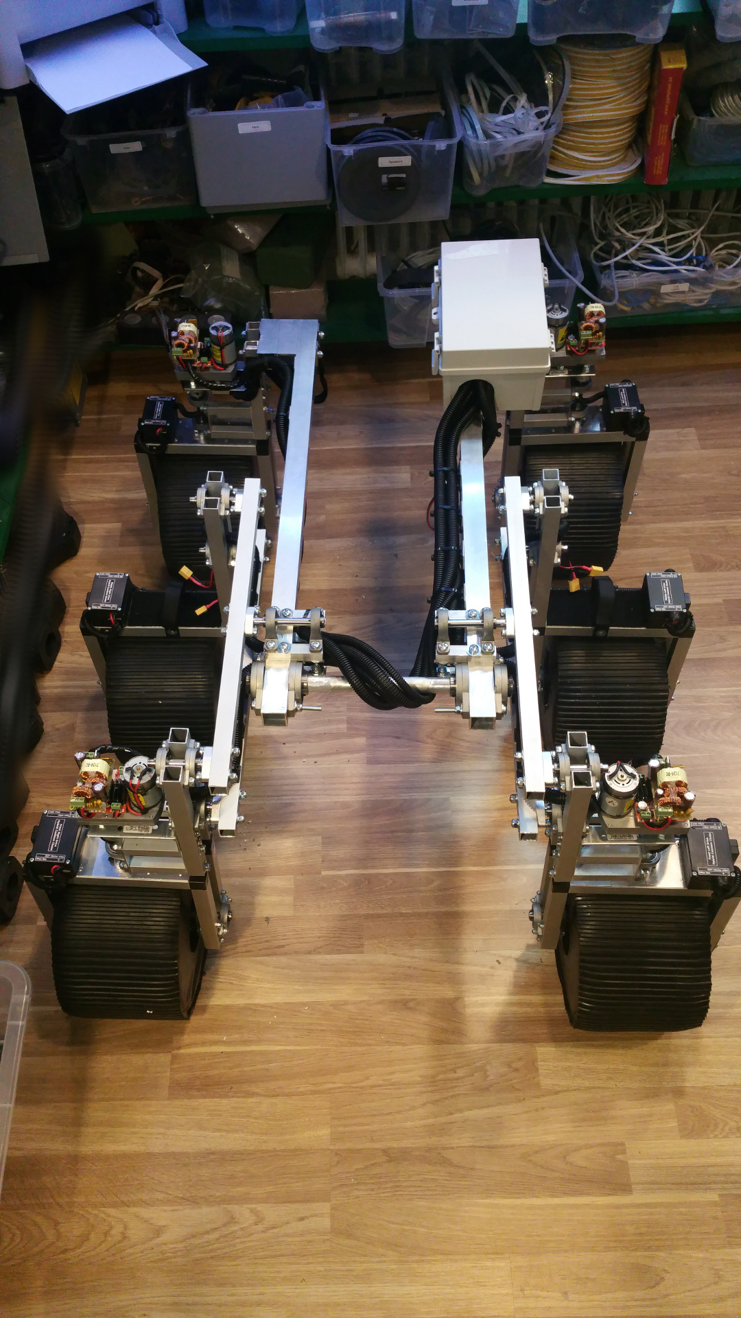
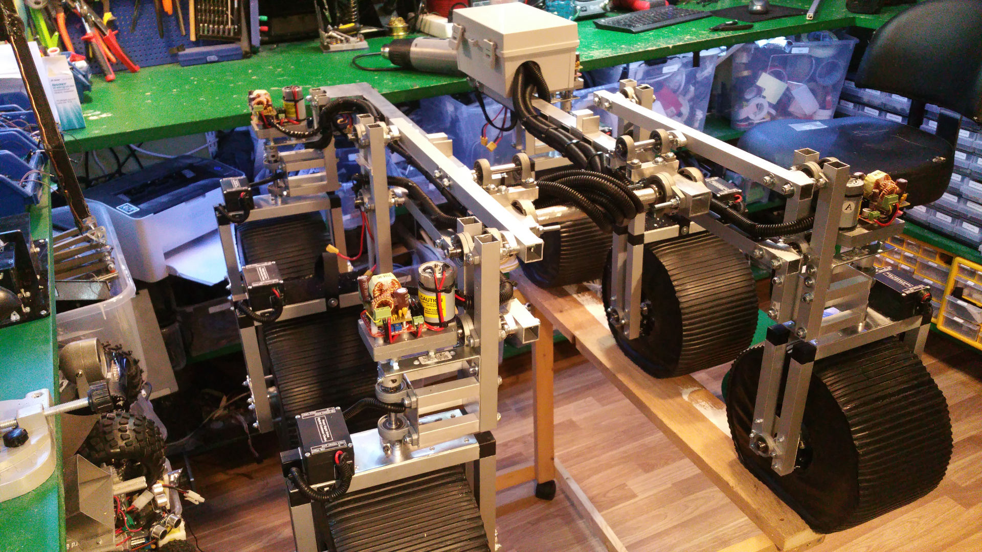
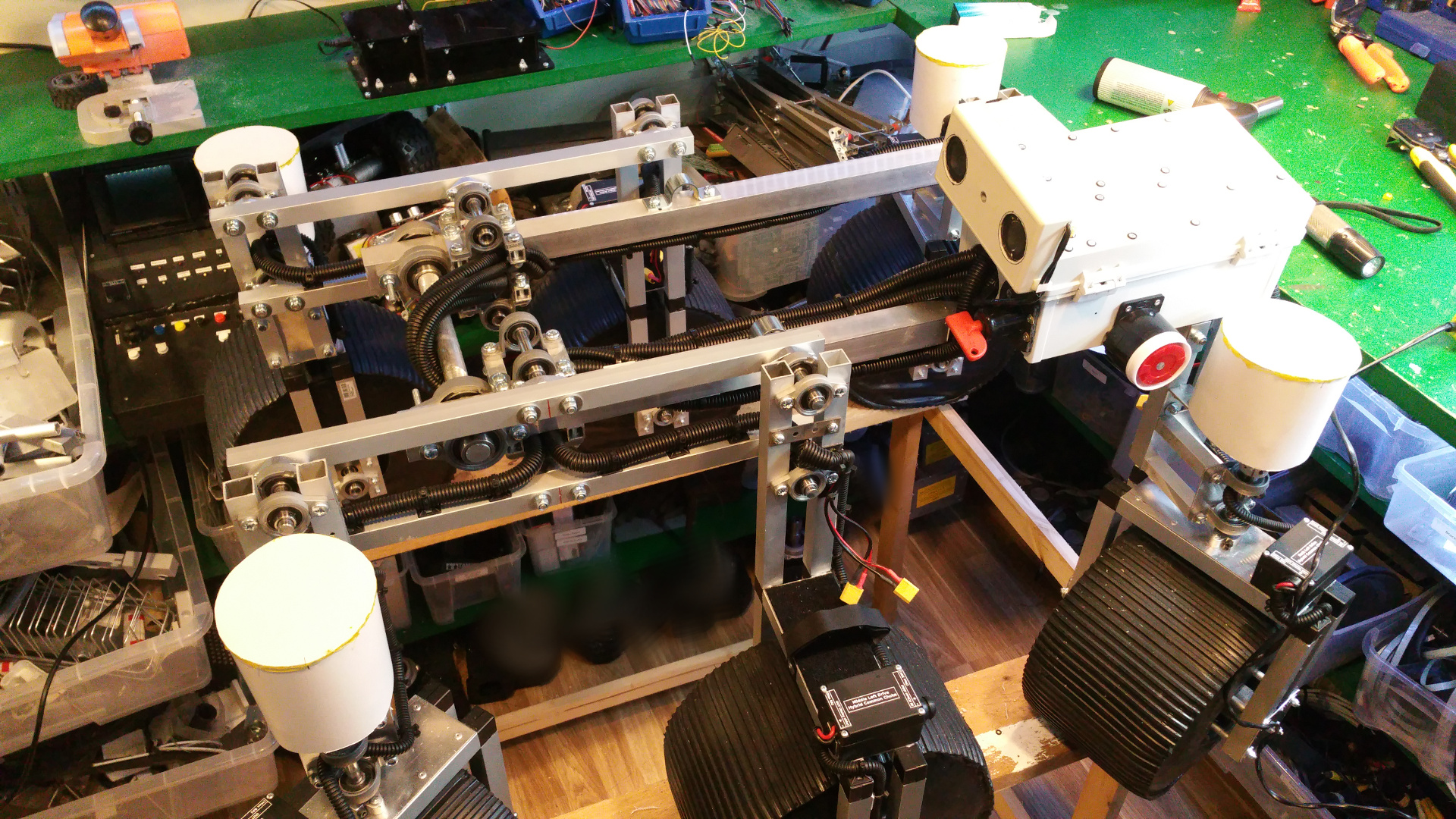
It is a 6wd rover with rocker suspension (Rocker-Bogie).
I did not like the skid steering from my last rover so this one can turn the front and rear wheels.
The last rover i built had no bearings so it was kind flimsy. So this one has bearings on all joints.
This page will be a work log for the build, think it will take pretty long time to complete...
| Contents |
| 2. Design |
| 3. Parts |
| 4. DC motors (Drive) |
| 5. Wheel rim |
| 6. Motor Mountings and wheel hub |
| 7. Tire (foam) |
| 8. Steering wheels |
| 9. Fixed wheels |
| 10. Back wheel link |
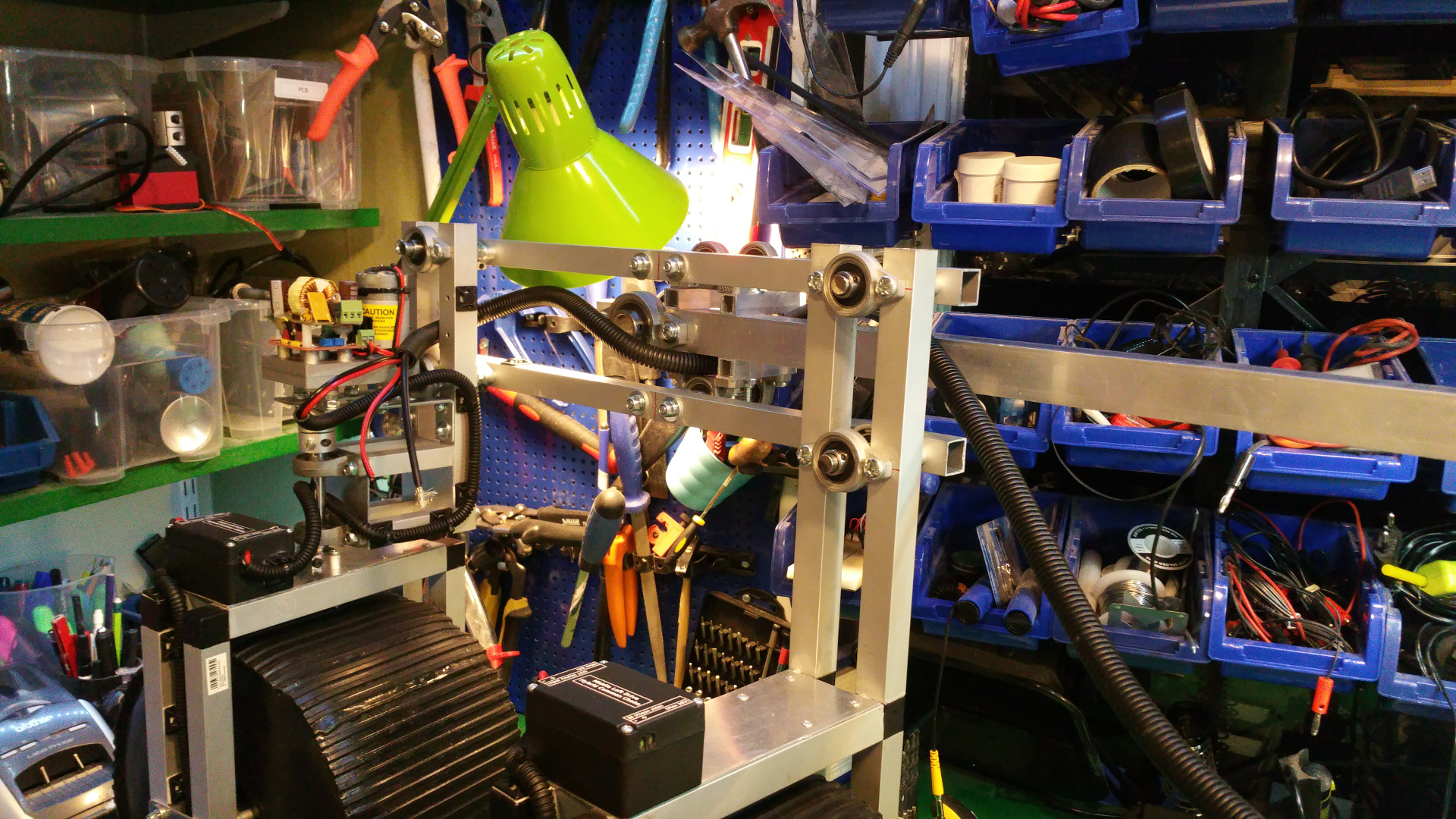
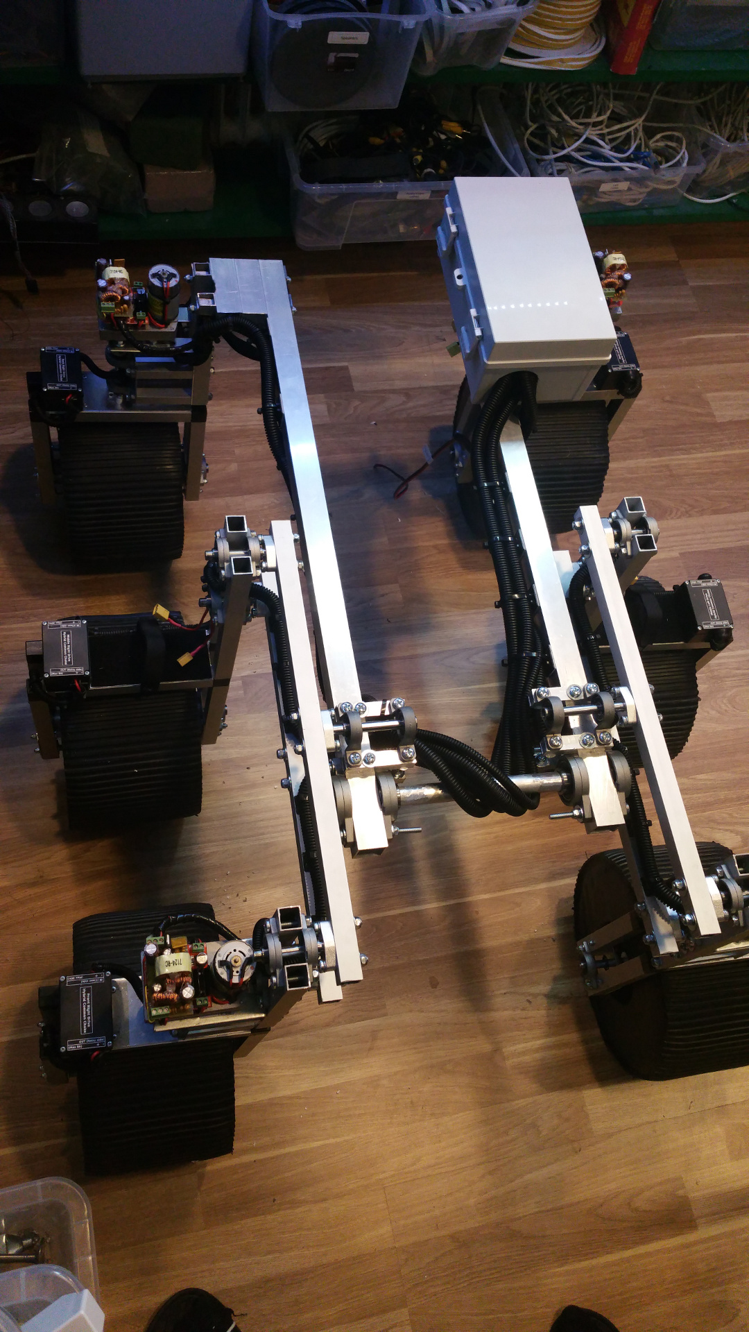
| 11. Connect wheel/bogie and frame |
| 12. Hybrid Common Choke |
| 13. Power distribution board |
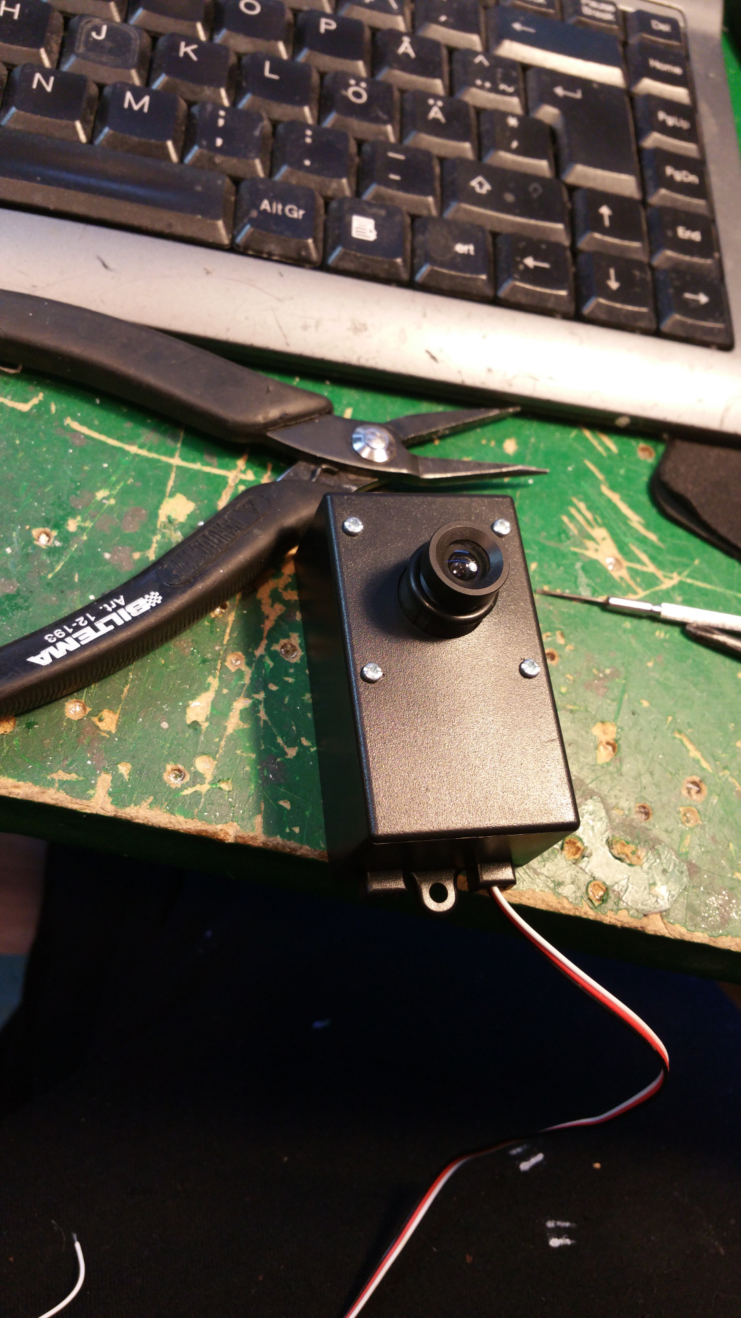
| 14. Camera |
| 15. Wiring |
2. Design
I want to make a more thoughtful design this time so I tried FreeCad.
It was pretty simple to learn the basic functionality so i use it to design the chassi.
It is not a construction drawing, just a sketch so i can figure out where stuff should be...
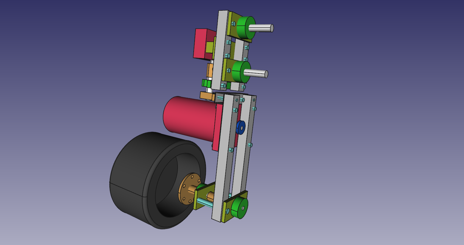

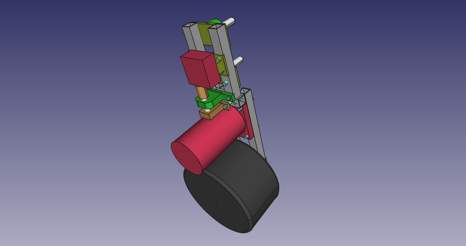
Above is the front wheel arm.
On my last rover the wheel was directly fixed to the motor and it could not handle the load. And because it stuck out so much it stuck in stuff.
I have change the motor placement, will have larger wheels and fit the motor inside the wheel.
The front and the back wheels will have servos to control steering.
The middle wheels will not have an steering.

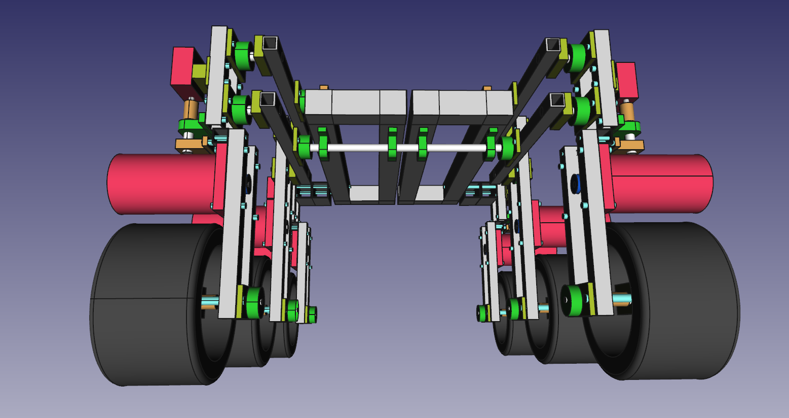
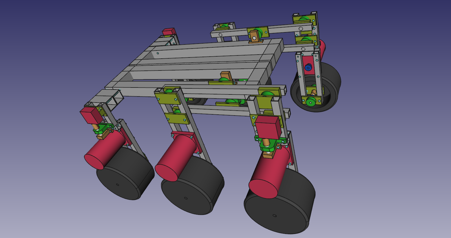

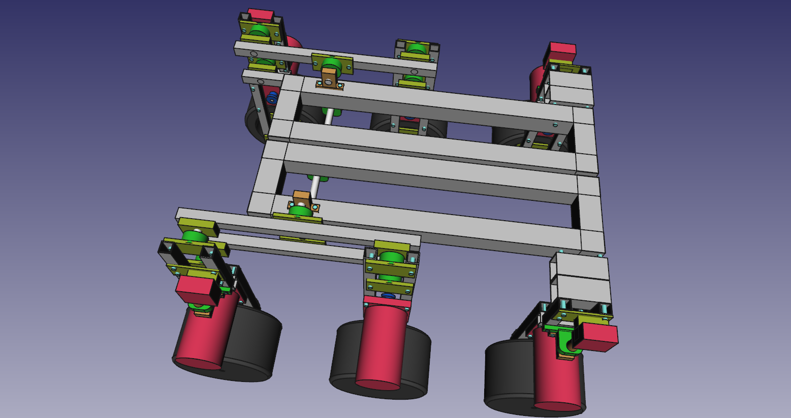

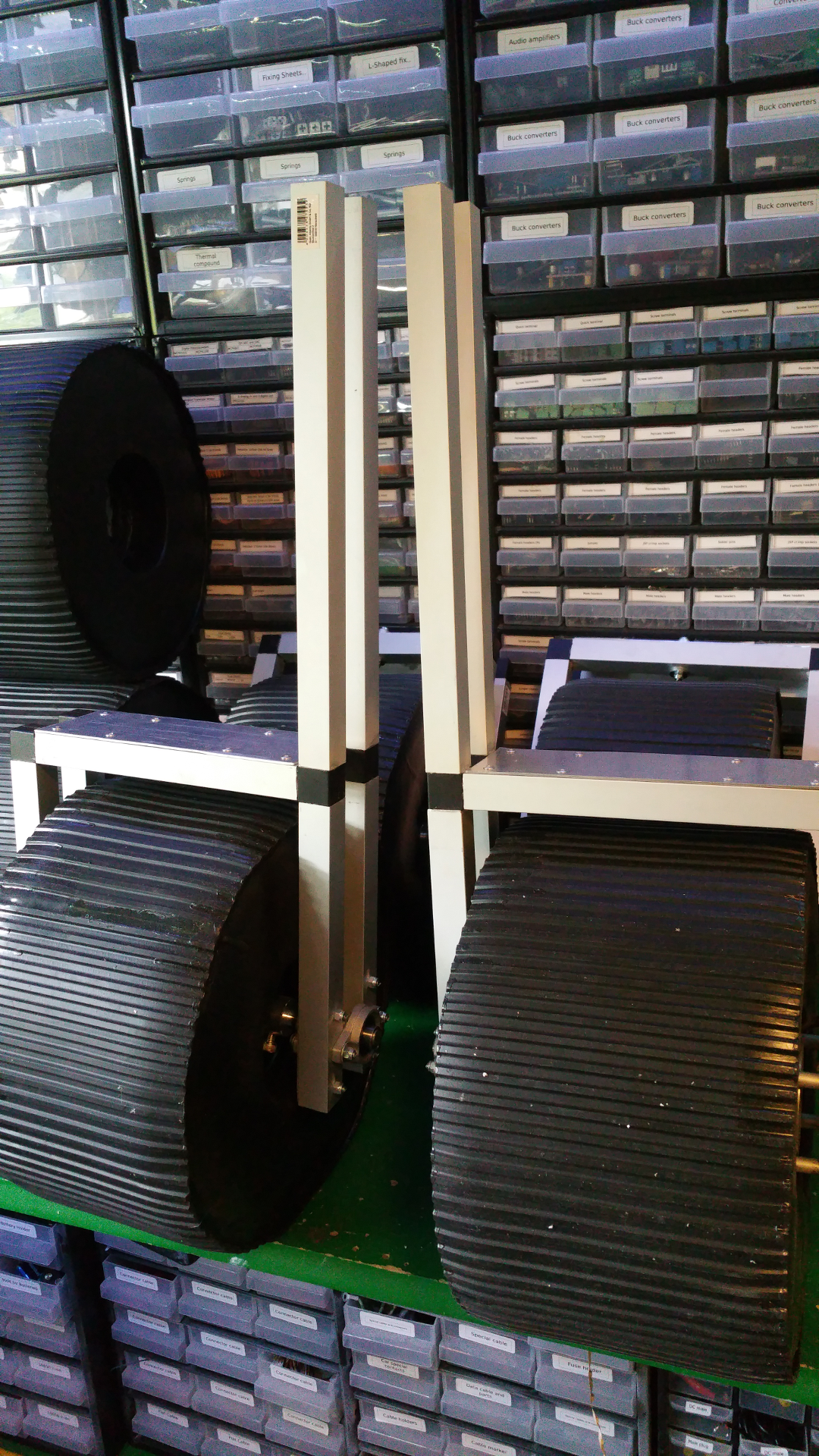
The 4 front wheel will have the rocker functionality and the 2 back wheel can move up and down separately.
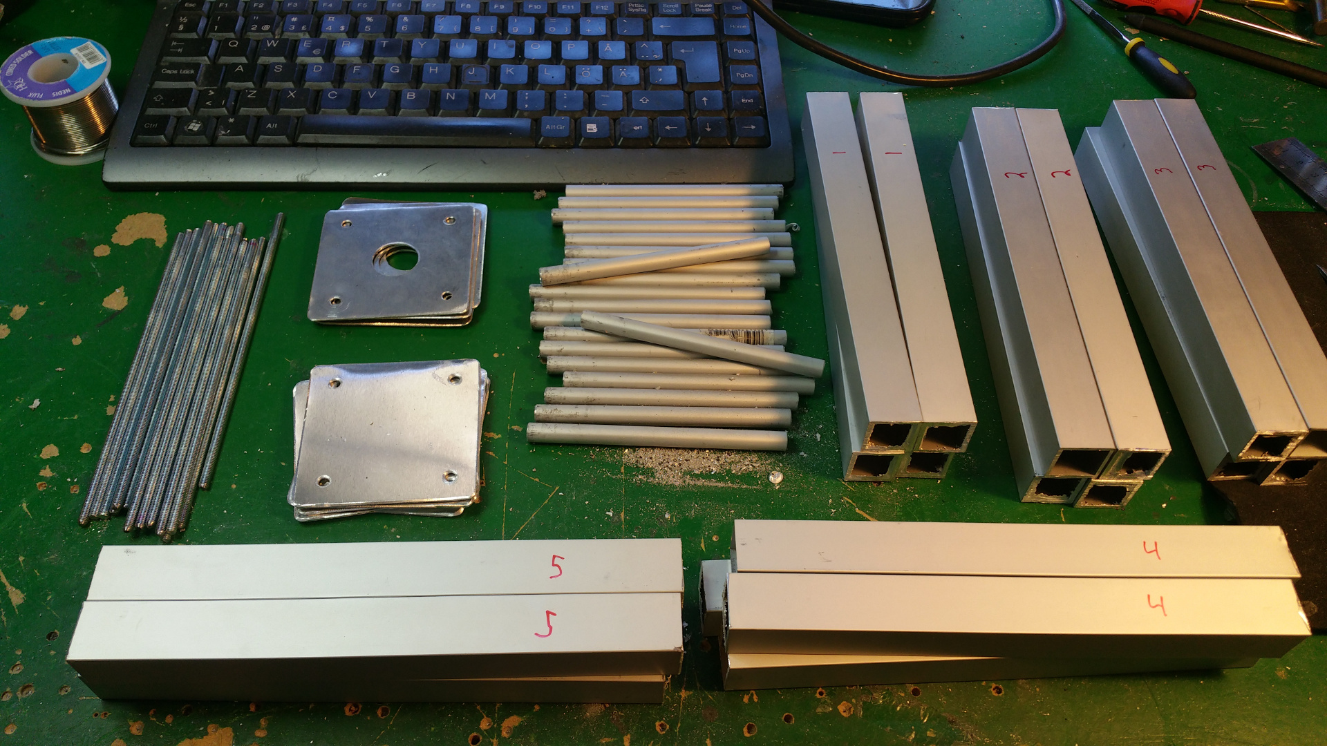
3. Parts
A lot of the parts is on its way from china now...
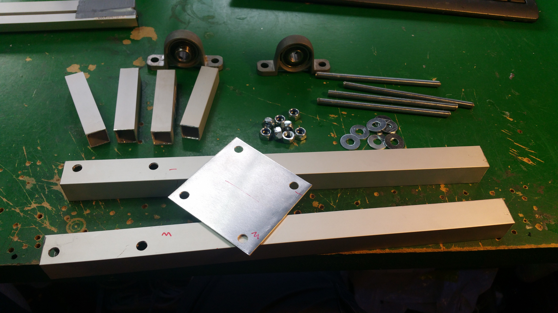
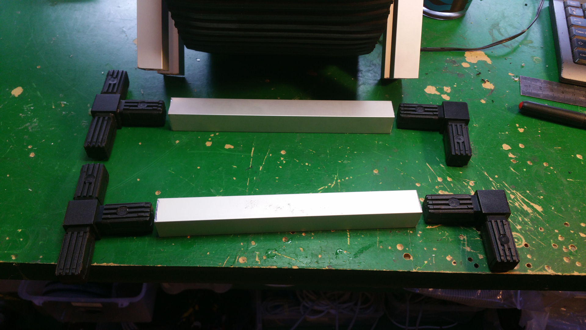
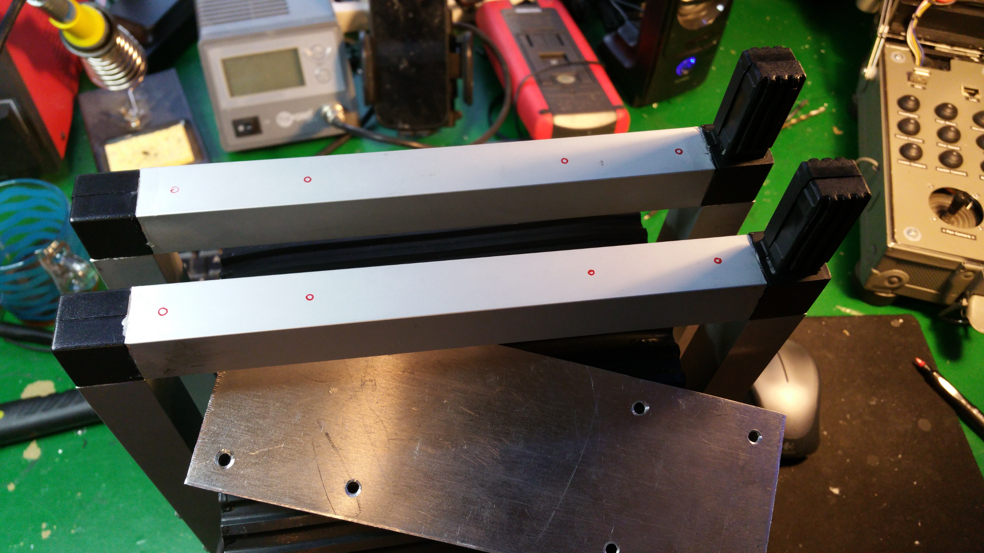
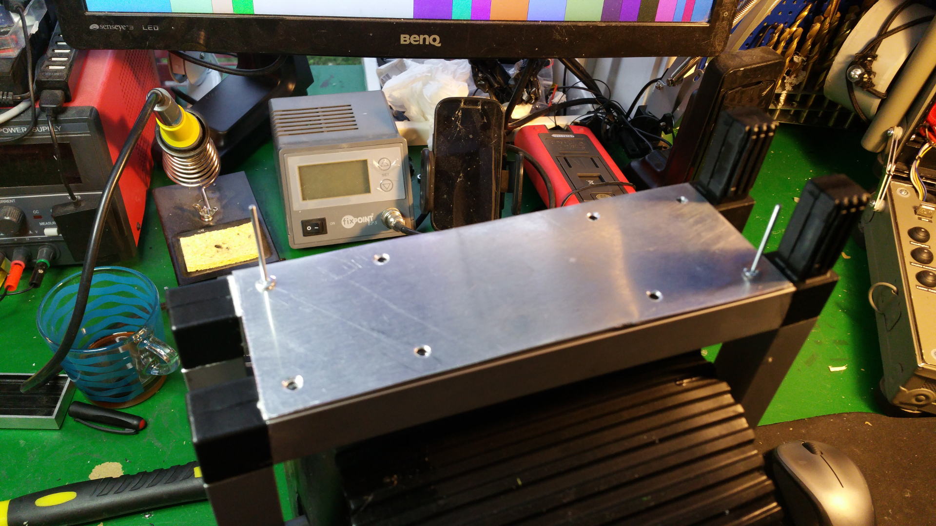
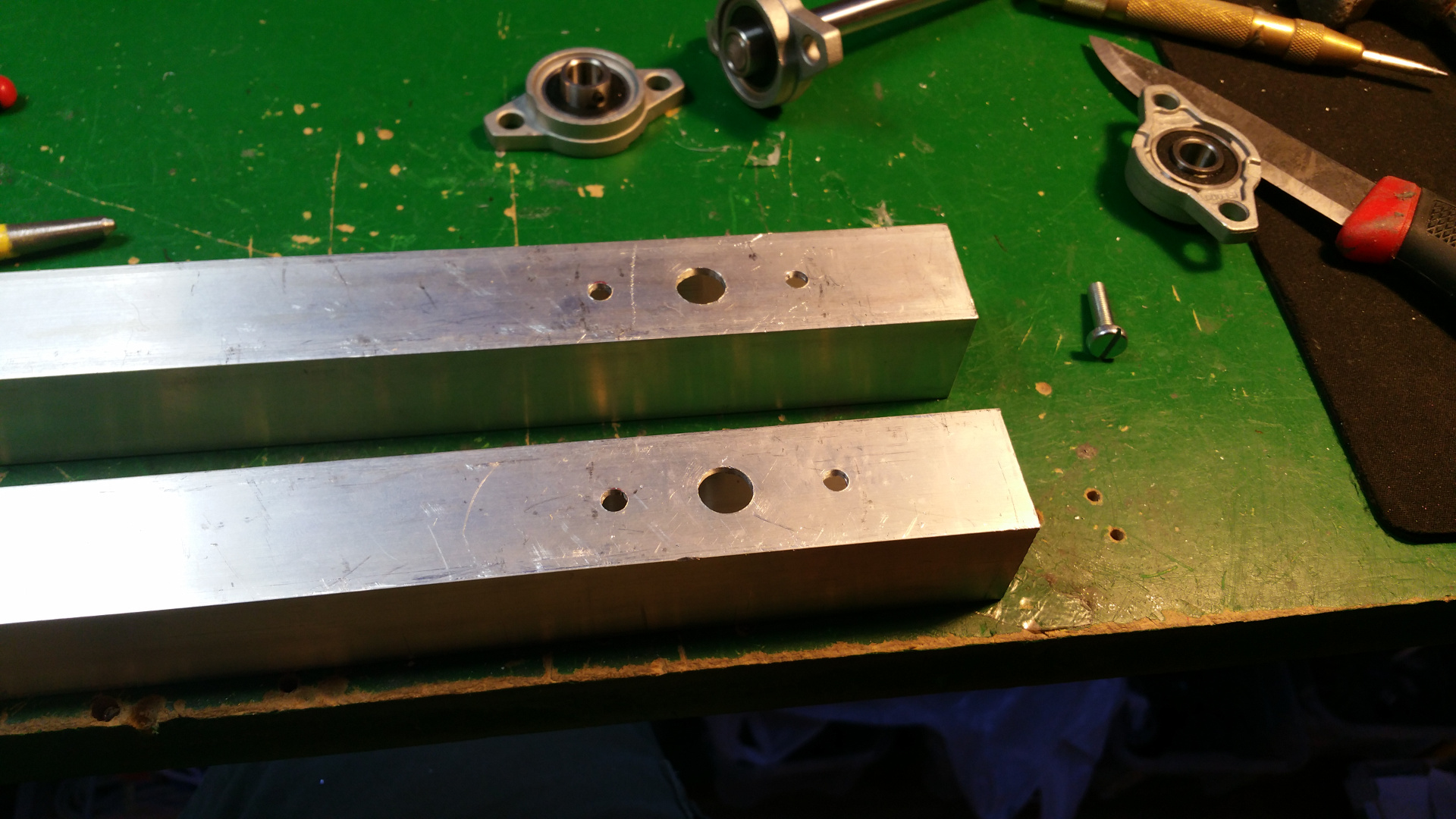
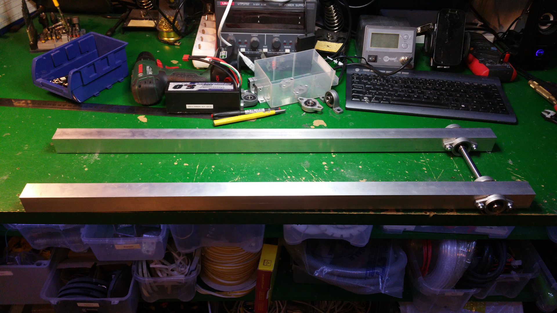
- The frame i will construct from 15mm and 30mm square aluminium tubing.
- 10 mm shafts
- 10 mm pillow block bearin
- 10 mm flange Block Bearing
- 6 mm flange Block Bearing
- Shaft coupling 6mm to 10mm
- Shaft coupling 8mm to 10mm (to connect the servo)
- 10 mm Horizontal shaft supports
- 10 mm Socket Stand shaft supports
- 6 GR12 12V DC 99.5-1 ratio Planetary Gearmotor (drive)
- ASME -03A High power high torque servo (Steer)
And a lot more....
The DC-motors i use is GR12 12V DC 99.5-1 ratio Planetary Gearmotor
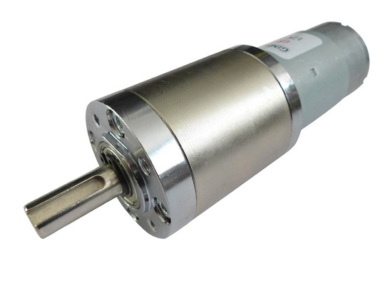
This will be the most expensive part of the project ... £45.60 peice :-(
But if the motors is as good as the specifications say then it will be worth it.
- 60RPM 12V DC motors with Metal Gearbox and Metal Gears
- Max. Efficiency Torque: 2.1 Nm
- Stall Torque: 11.9 Nm
- No-load current: 0.6 A
- Stall current: 11.4 A
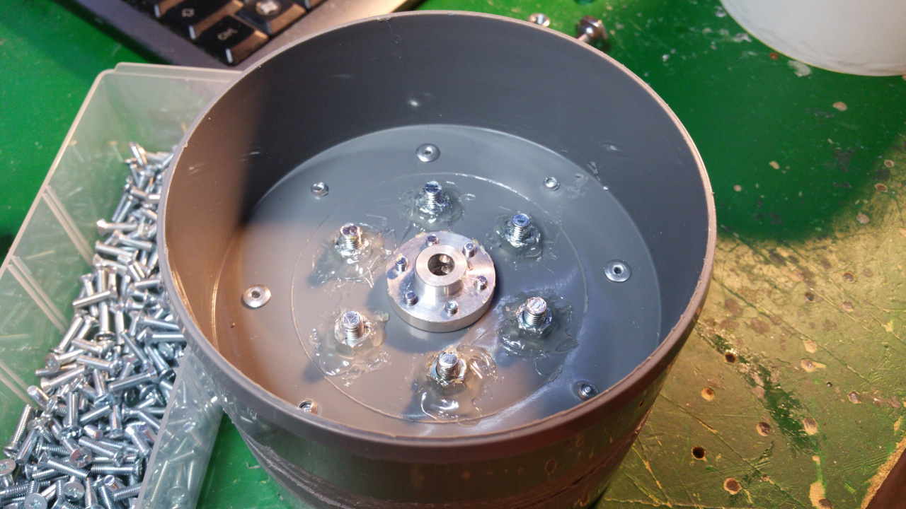
5. Wheel rim
I have change the construction of the wheels, the motors will be inside the hub of the wheel.
And the wheels will be much bigger. On one side (outside) of the hub the motor is fitted and on the other side a shaft with bearing.
-
The hub is made out off two 110 MM sewer pipe sleeves (i think its called...)
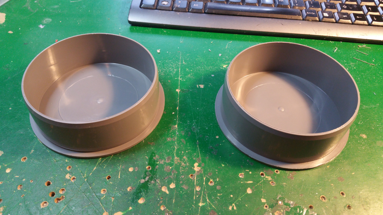

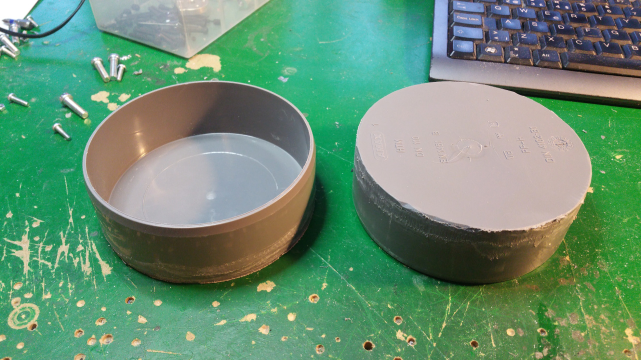
- Riveted together the two sleeves
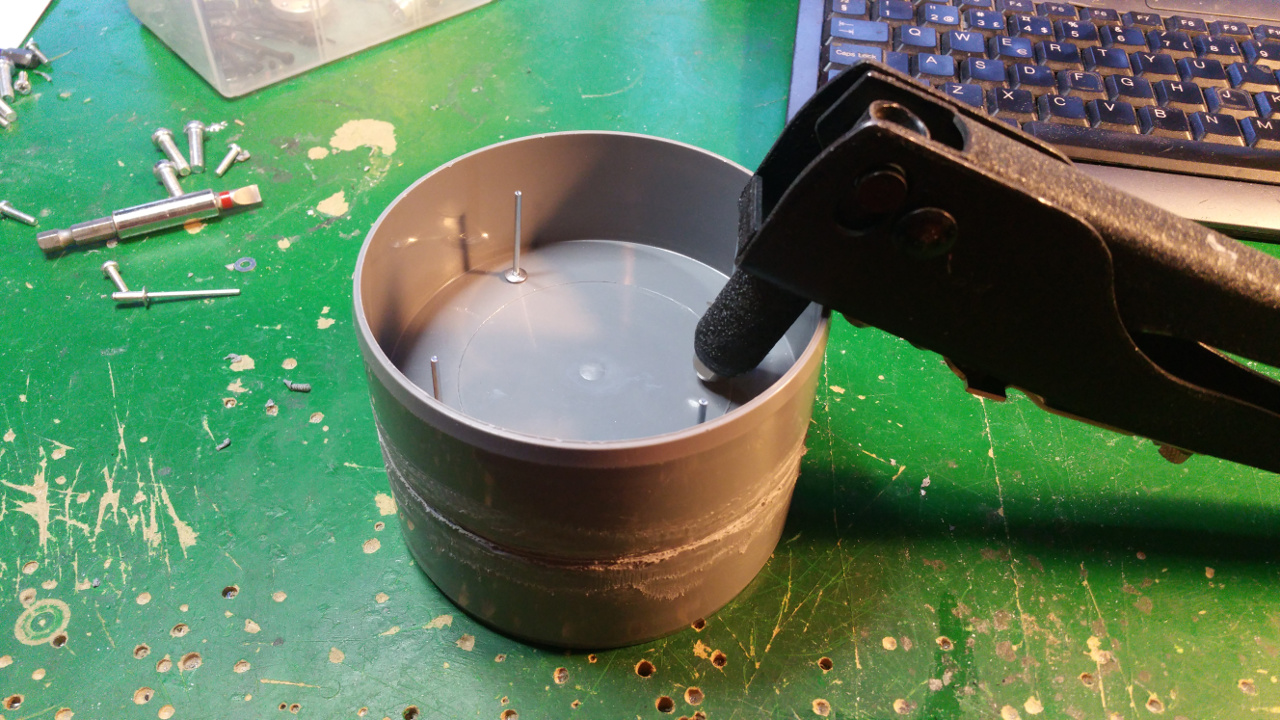
- Then it is time to fit the 6mm mount for the motor shaft.
- On the other side fix the 10mm shaft mount for the bearing.
This is to get extra stability, the small 6mm shaft and bearing on the motor is to weak.

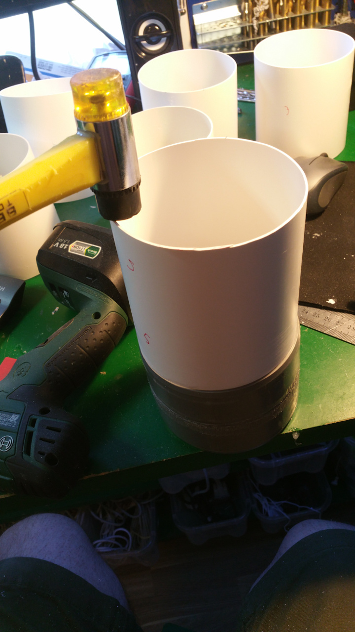
- The rest of the hub, where the motor is to be i use a Telescopic Ventilation pipe.
On one end of the outer pipe you need to sand it down or it will be hard to fit it on the sewer pipe.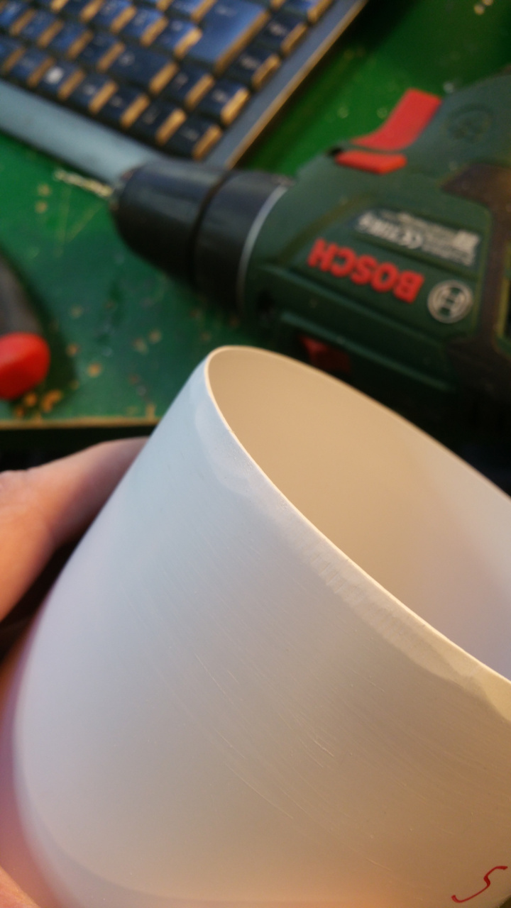


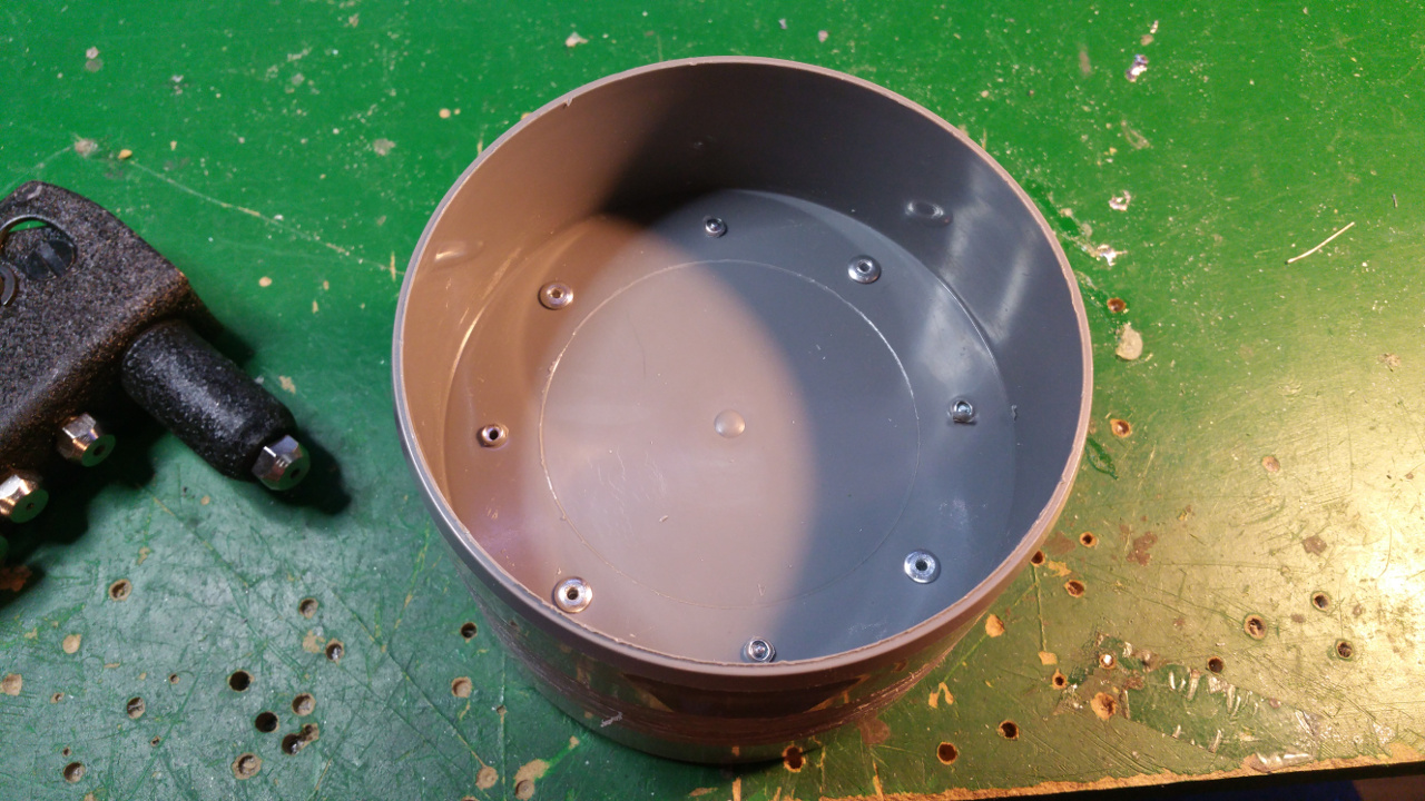
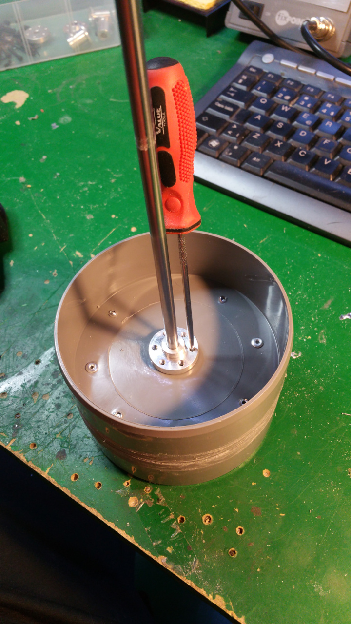
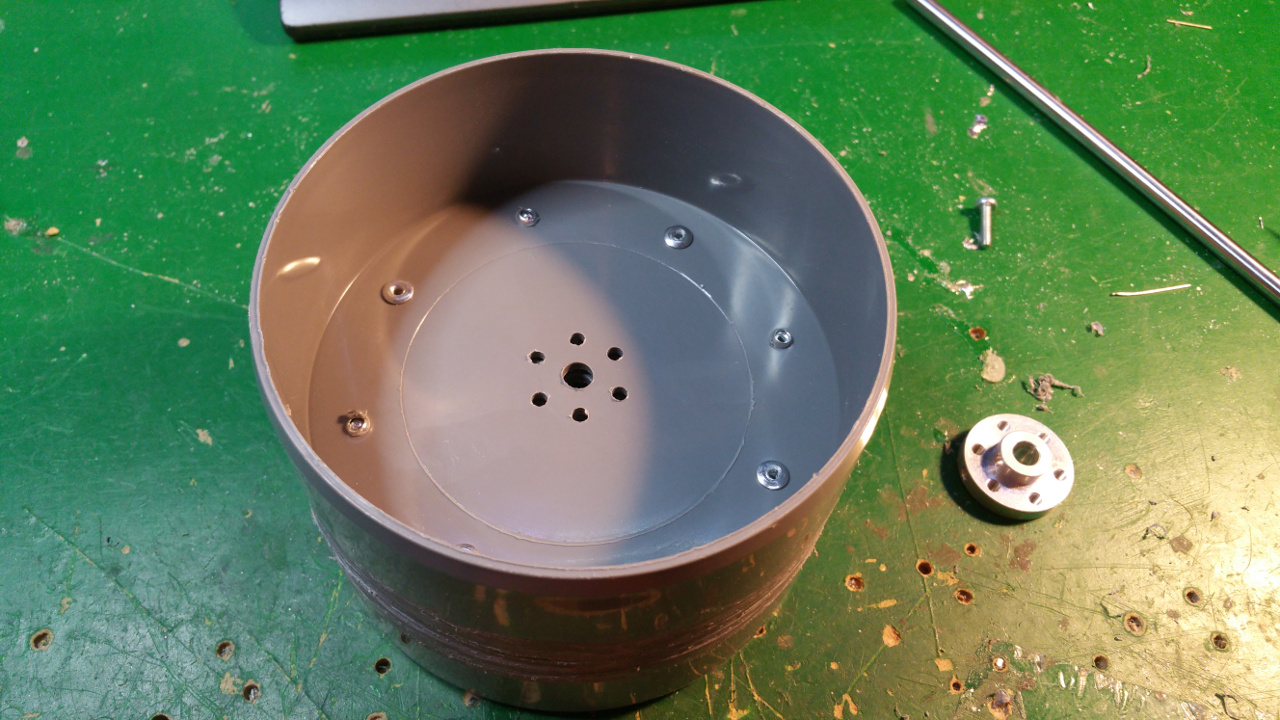
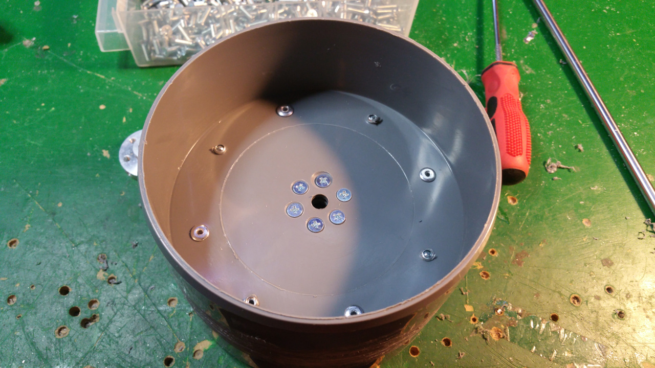
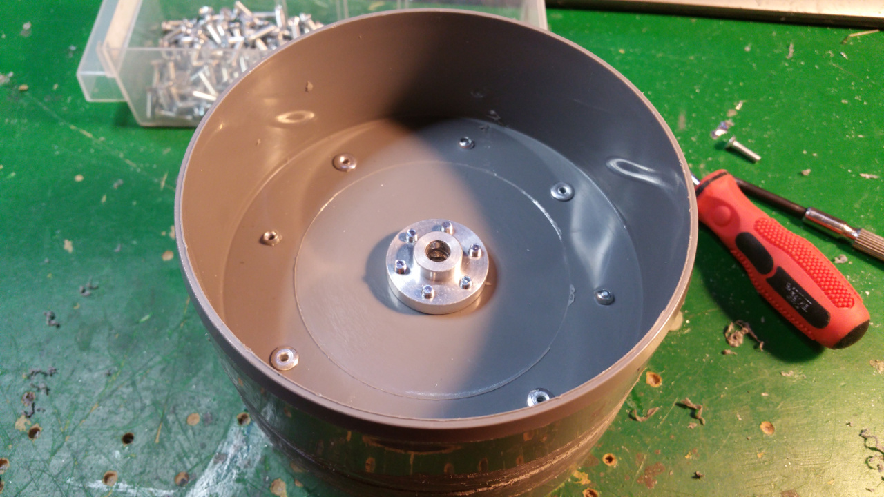
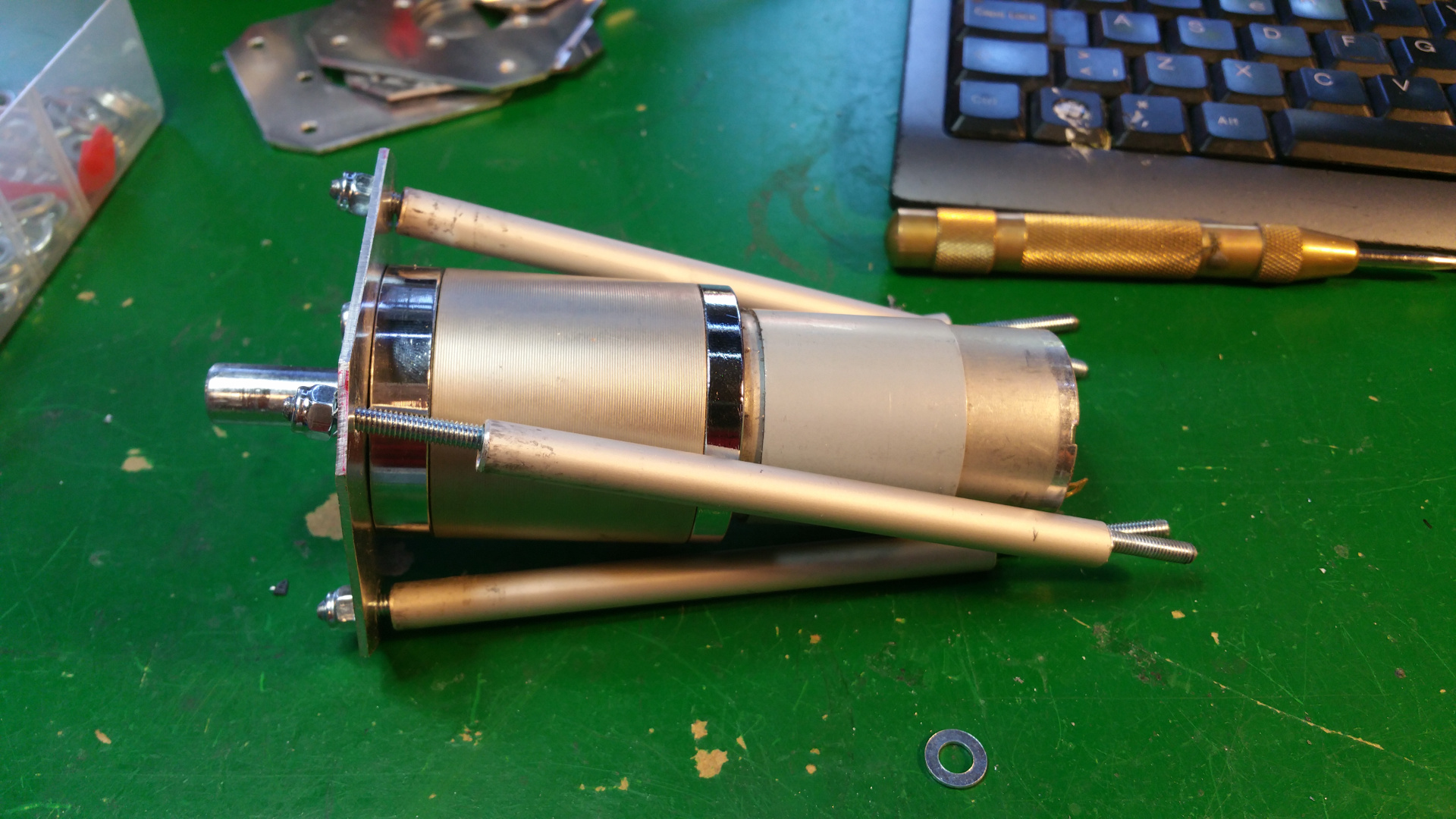
6. Motor Mountings and wheel hub
- Lot of stuff...
- The motor need some special mounting to be able to fit inside the wheels.
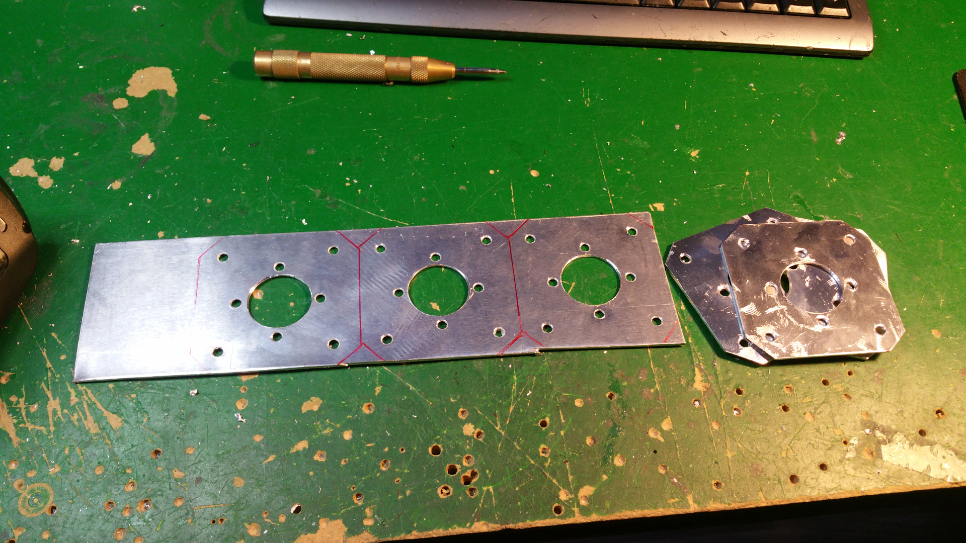
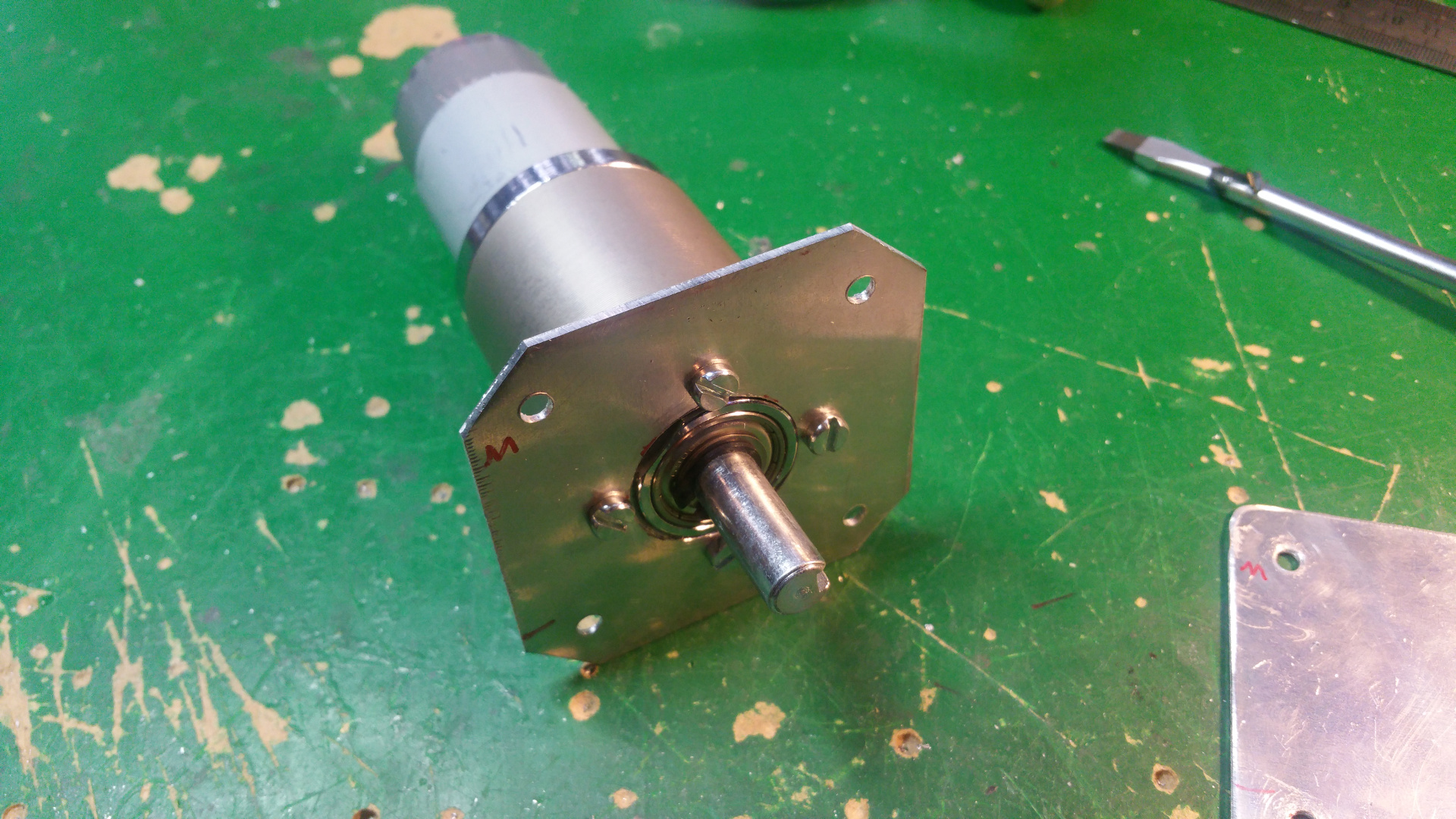
I use some fixing paste so the bolts is fixed if i must remove the motor later when all is done.

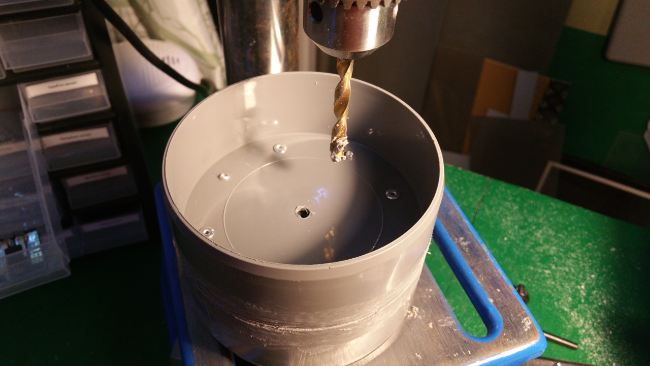
- Need to drill hole in the shaft fixing so i can connect the motor fixing from the same side as the shaft.

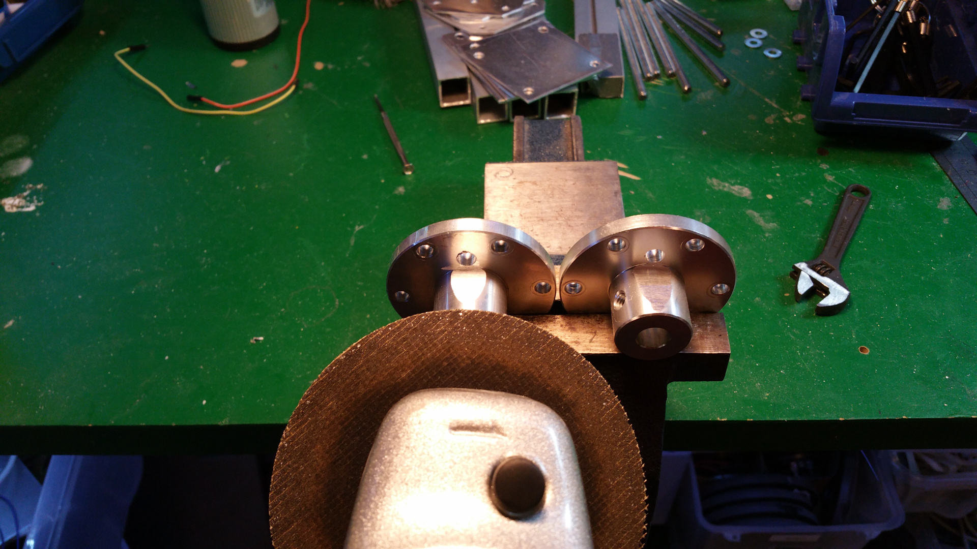
- Test that the motor fit.

- The wheel hub with bearings.

I will cut the shaft later... 
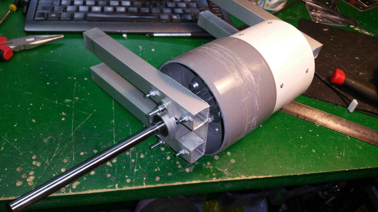
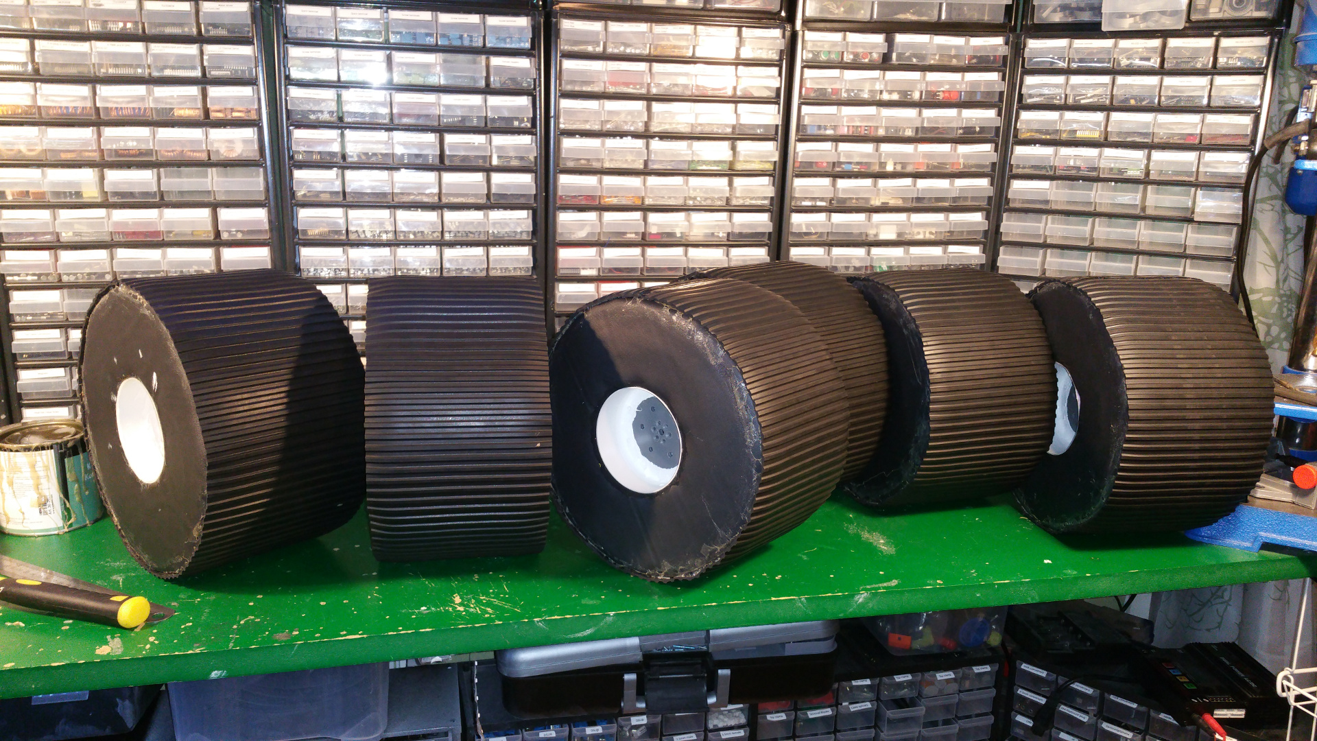
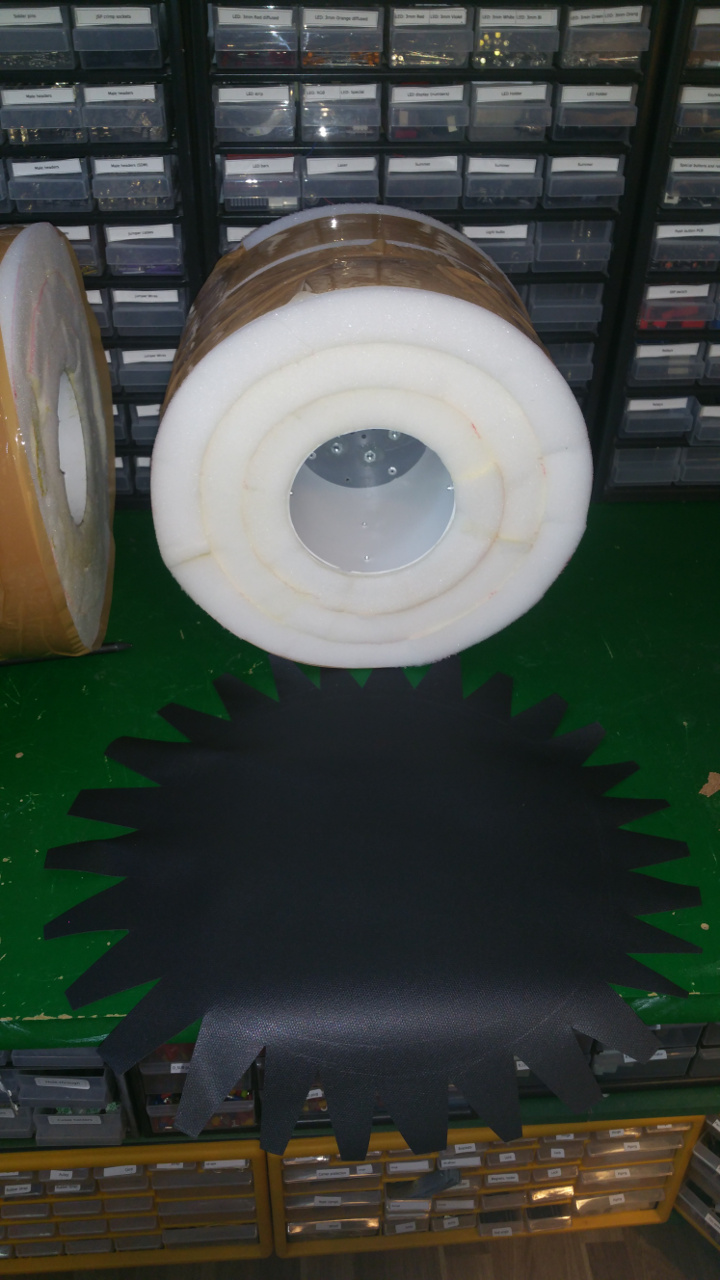
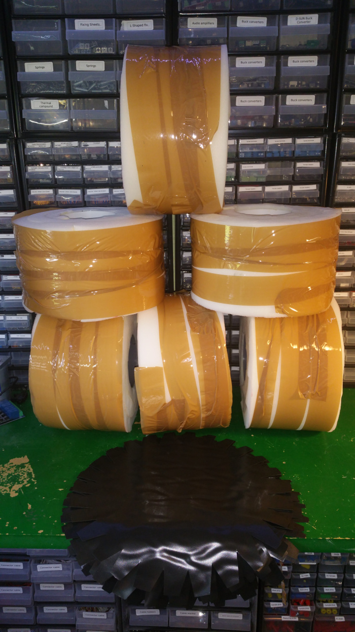
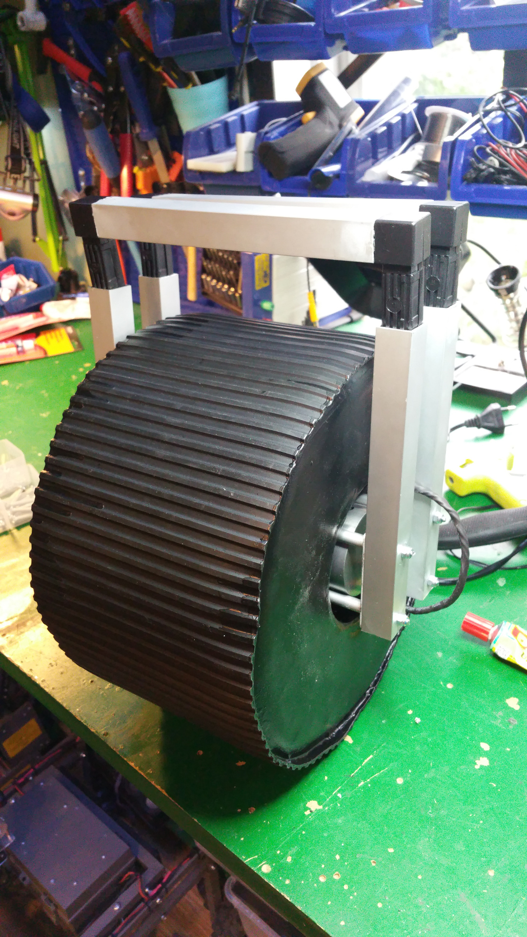
7. Tire (foam)
- The tire is just foam that i will fit rubber around.
I use spray contact adhesive to fix three layers of foam (3cm).
The wheel is pretty big, about 28cm in diameter.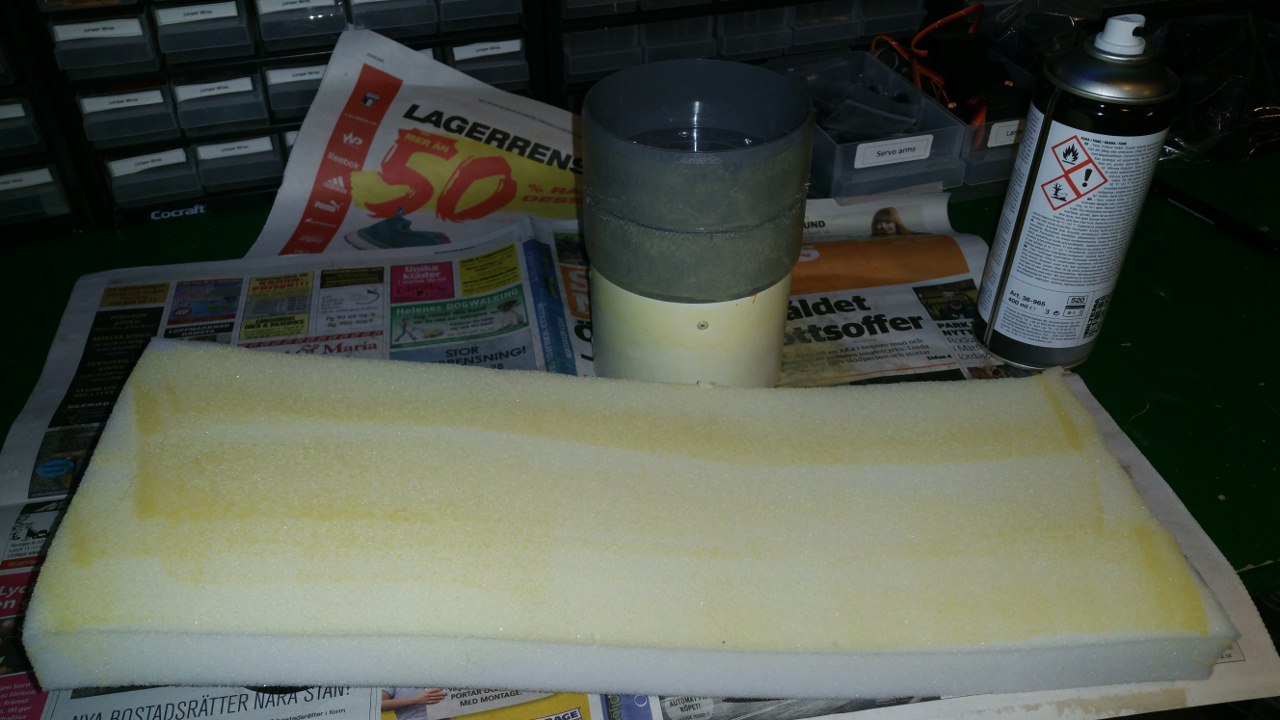
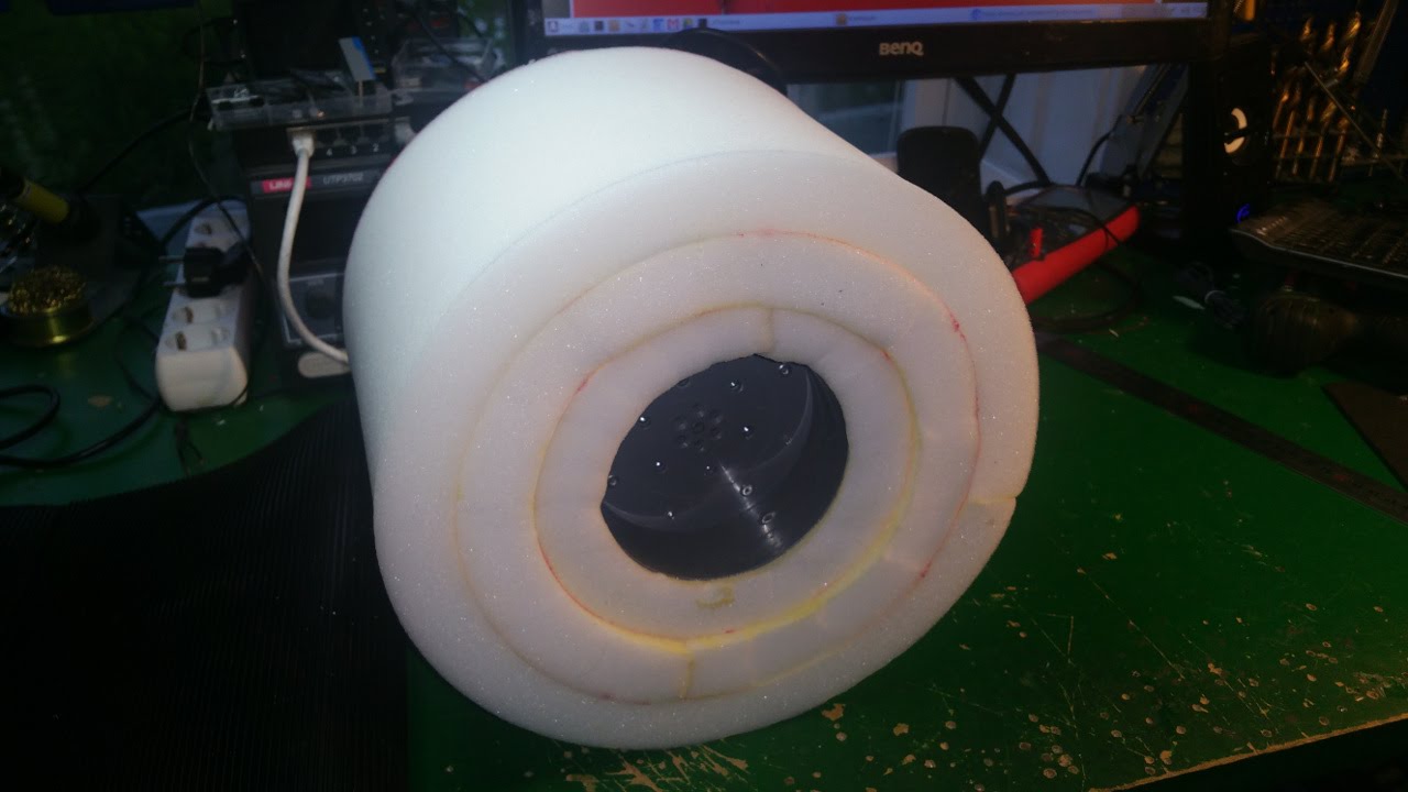
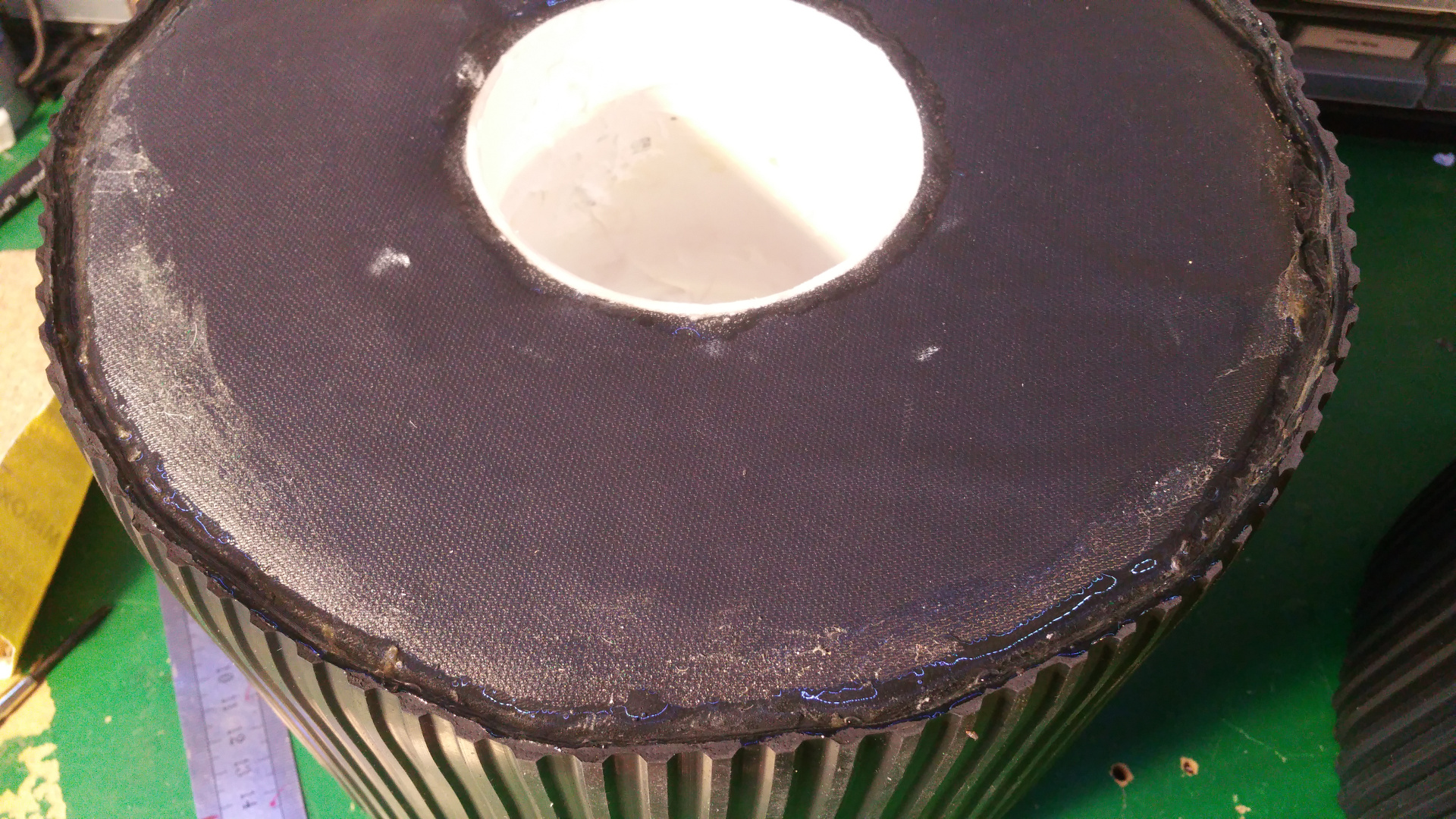
- To fix the rubber in the center hub i glue and hammer in a plastic ring, on one side i use the rest of Telescopic Ventilation pipe.
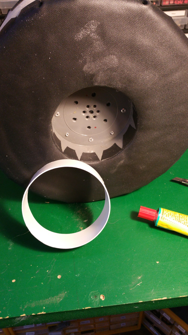
- And on the other side a joint for the ventilation pipe.
Also need to cut out for the rivet.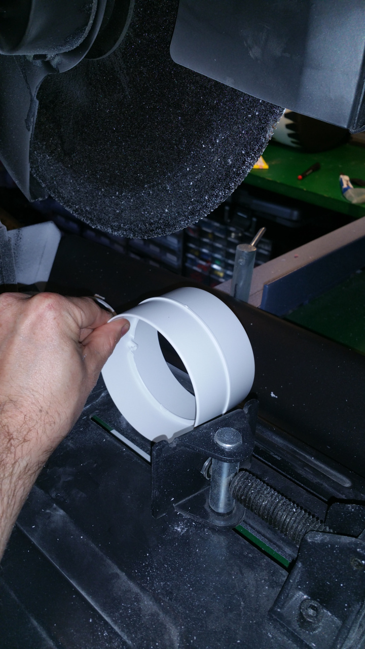
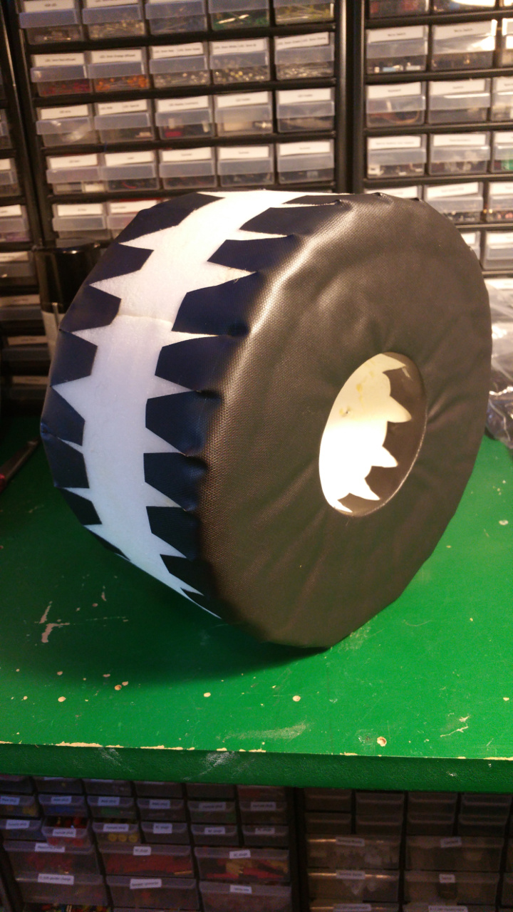
- Also glue the rest of the tire with the rubber that you use for small pools.

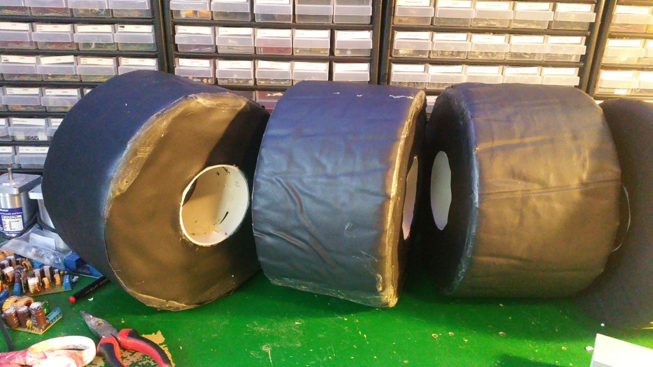
- Final step is to fix the some type of tread for the tires.
i use some rubber flooring.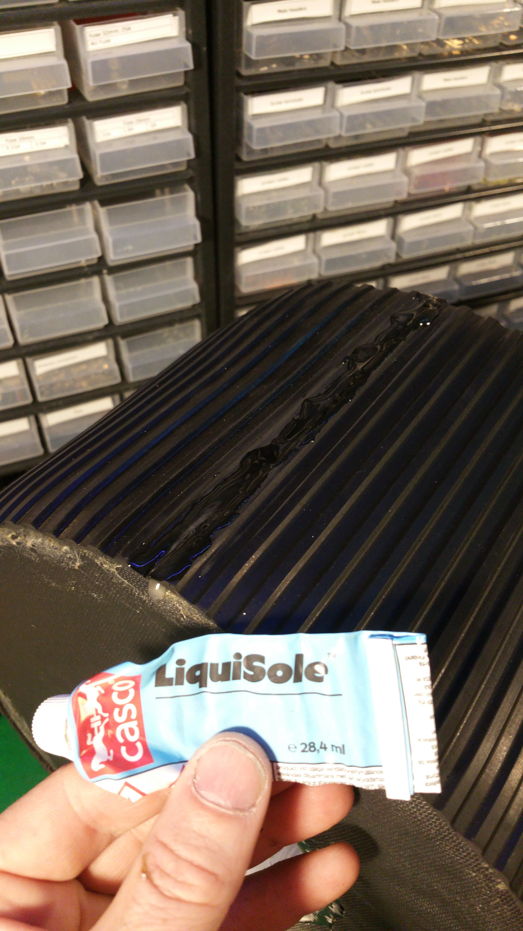


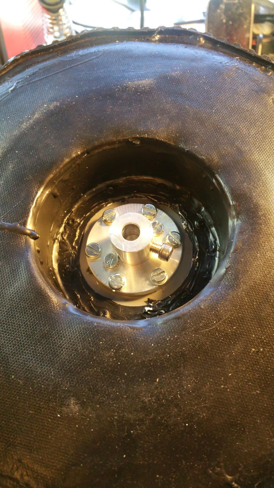
8. Steering wheels
- The front and back wheels have steering. This is the arm that connect to the wheel.
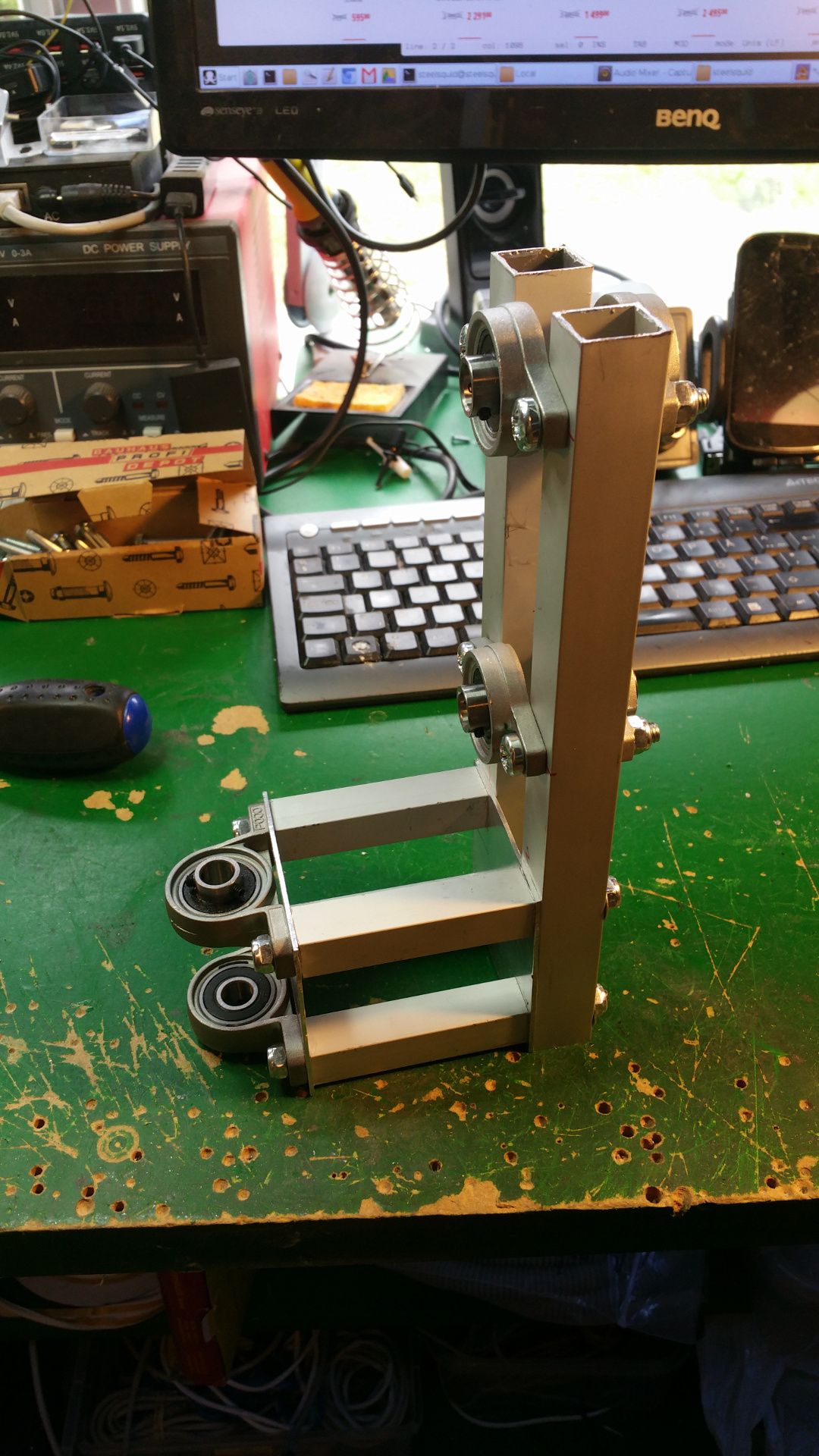
- The wheel connection.

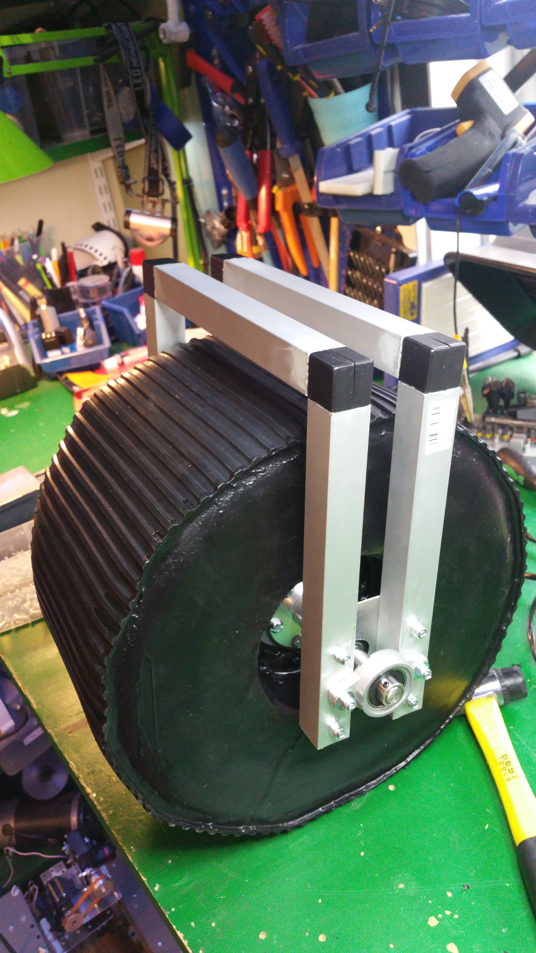


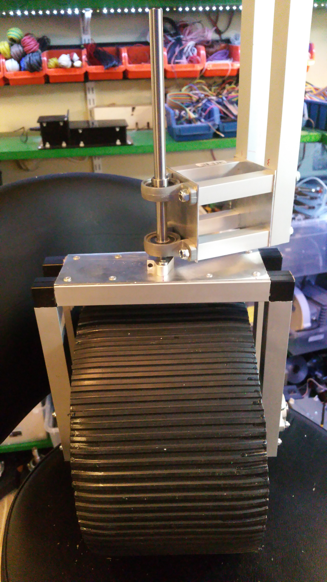
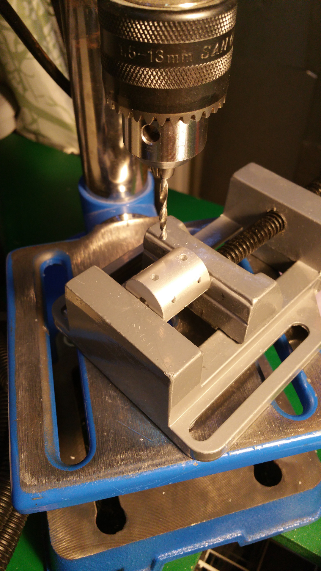
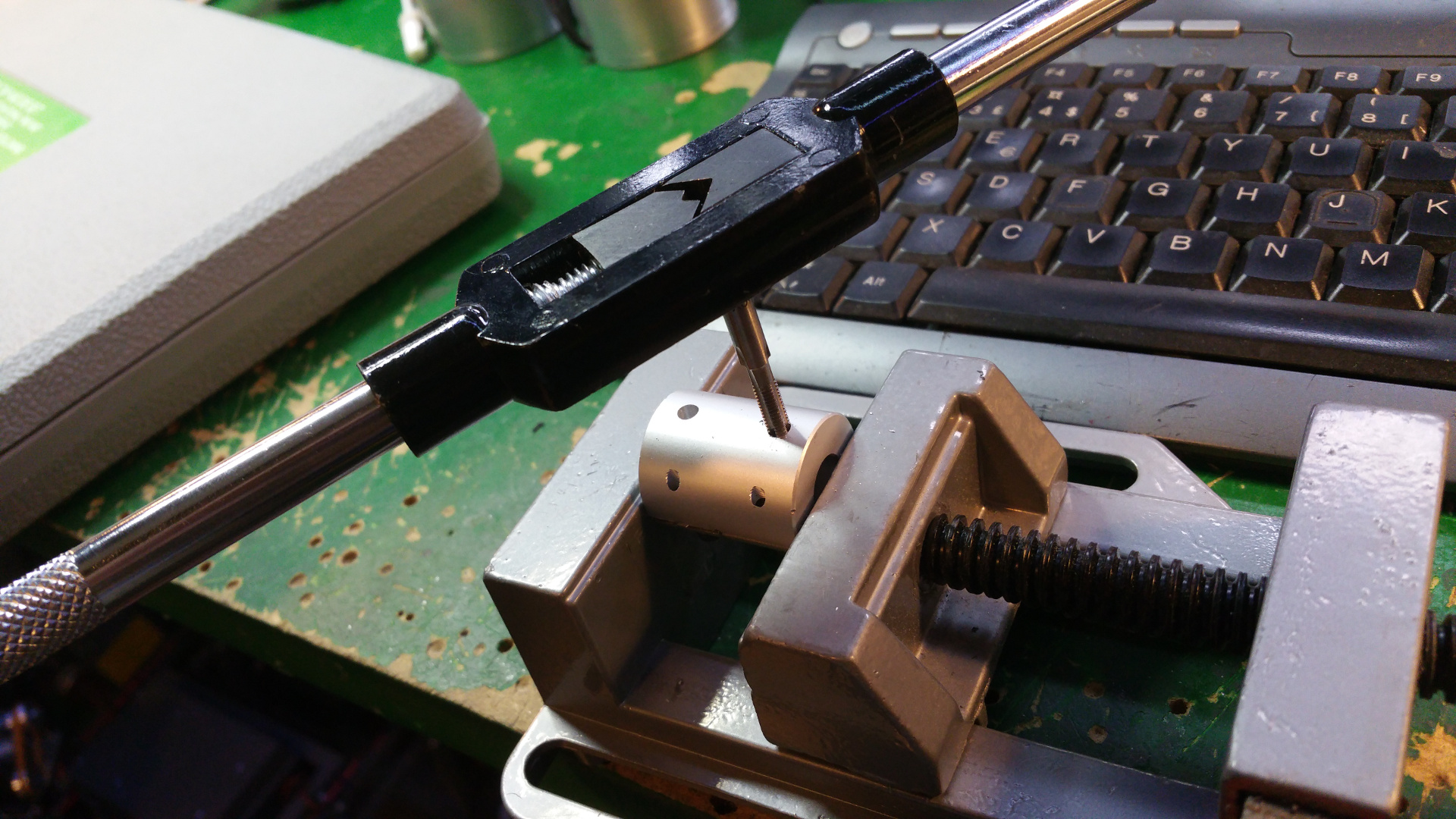
- Servo motor to steer wheel, first need to drill hole and thread it so the shaft can connect to the servo.


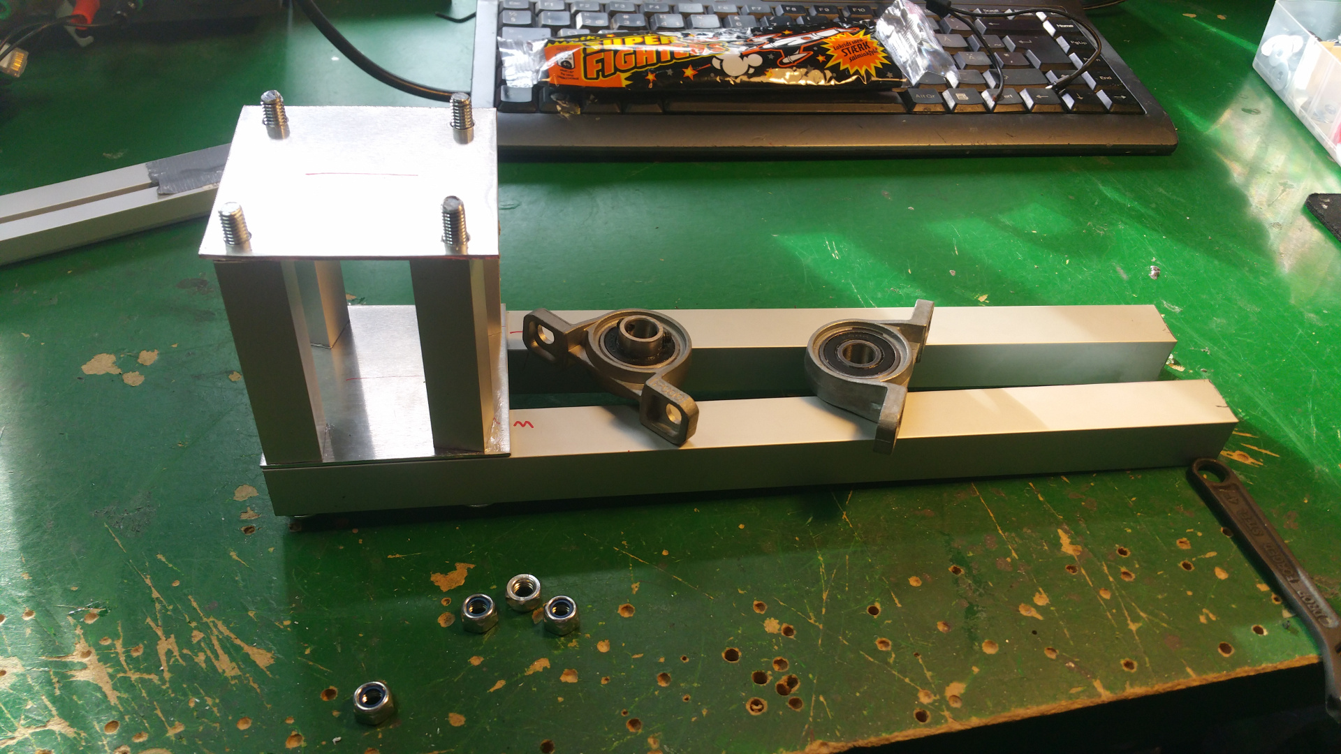
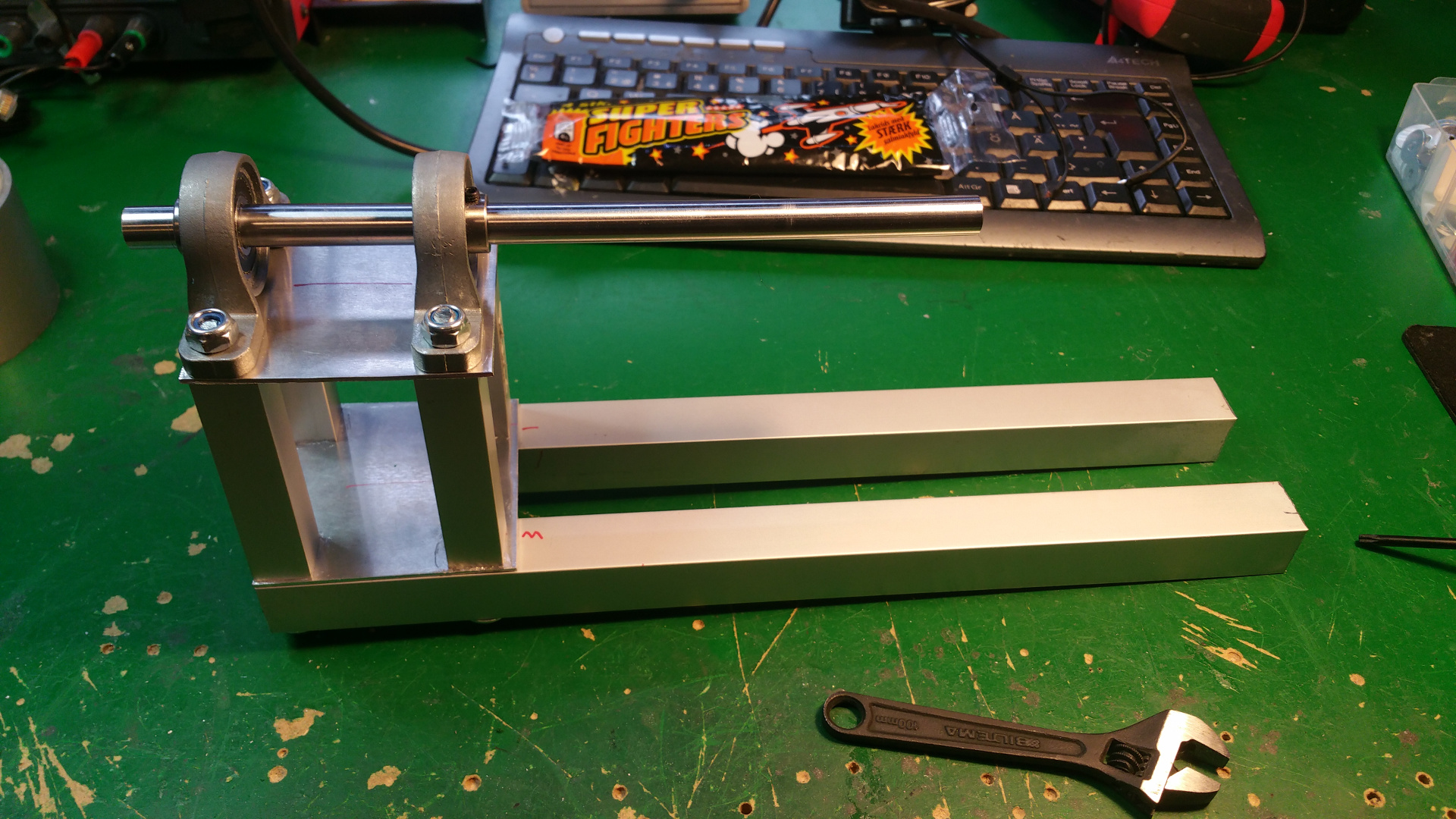
10. Back wheel link
The link that connect the two half of the rower.
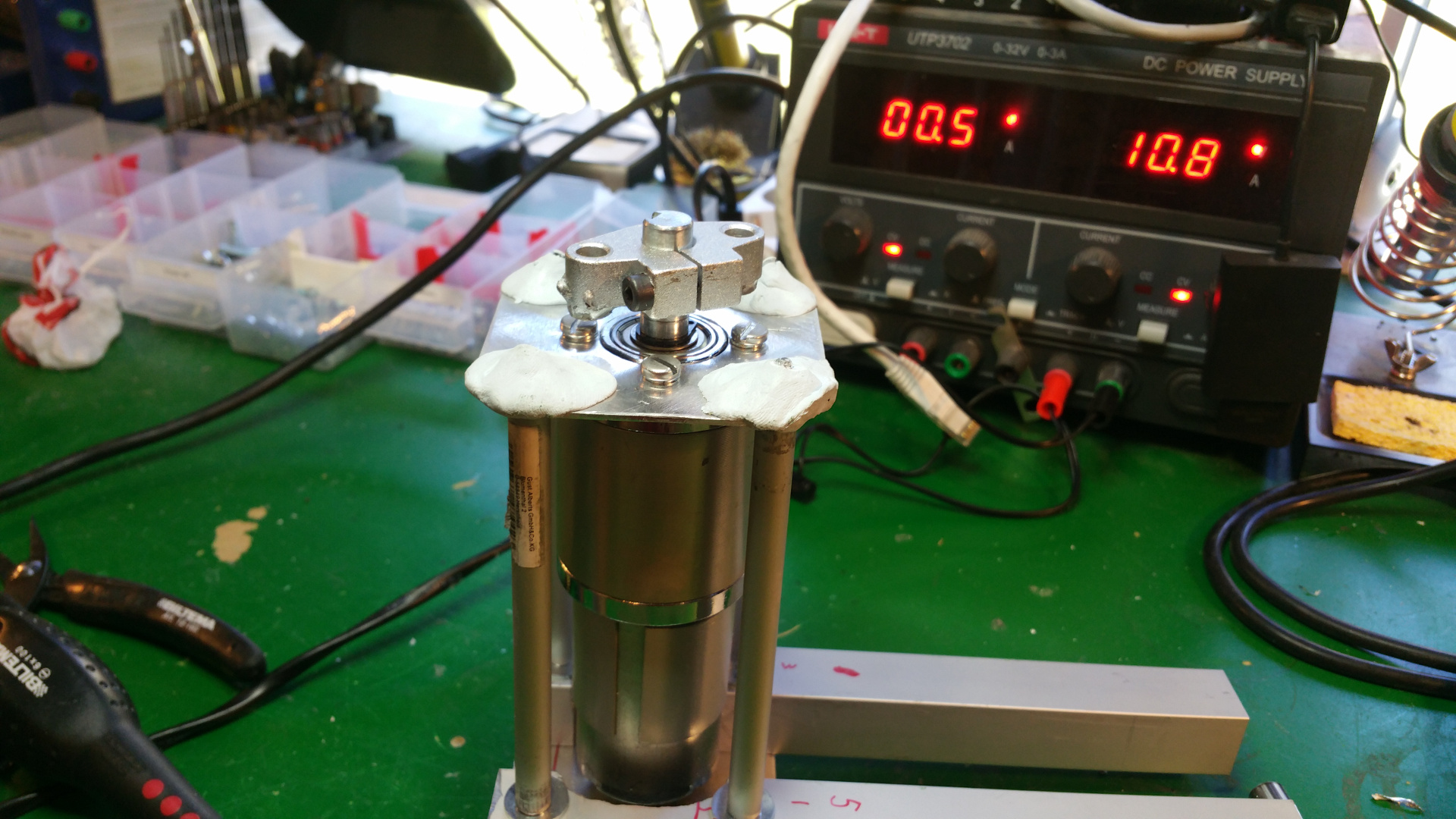
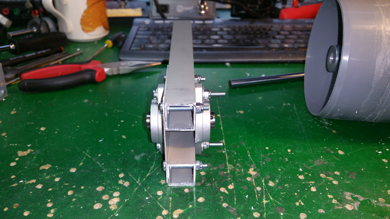
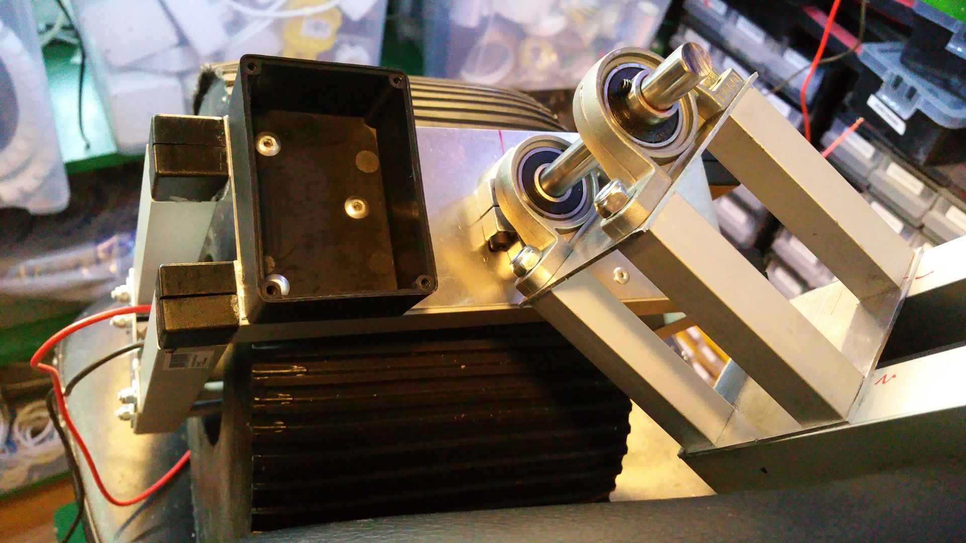
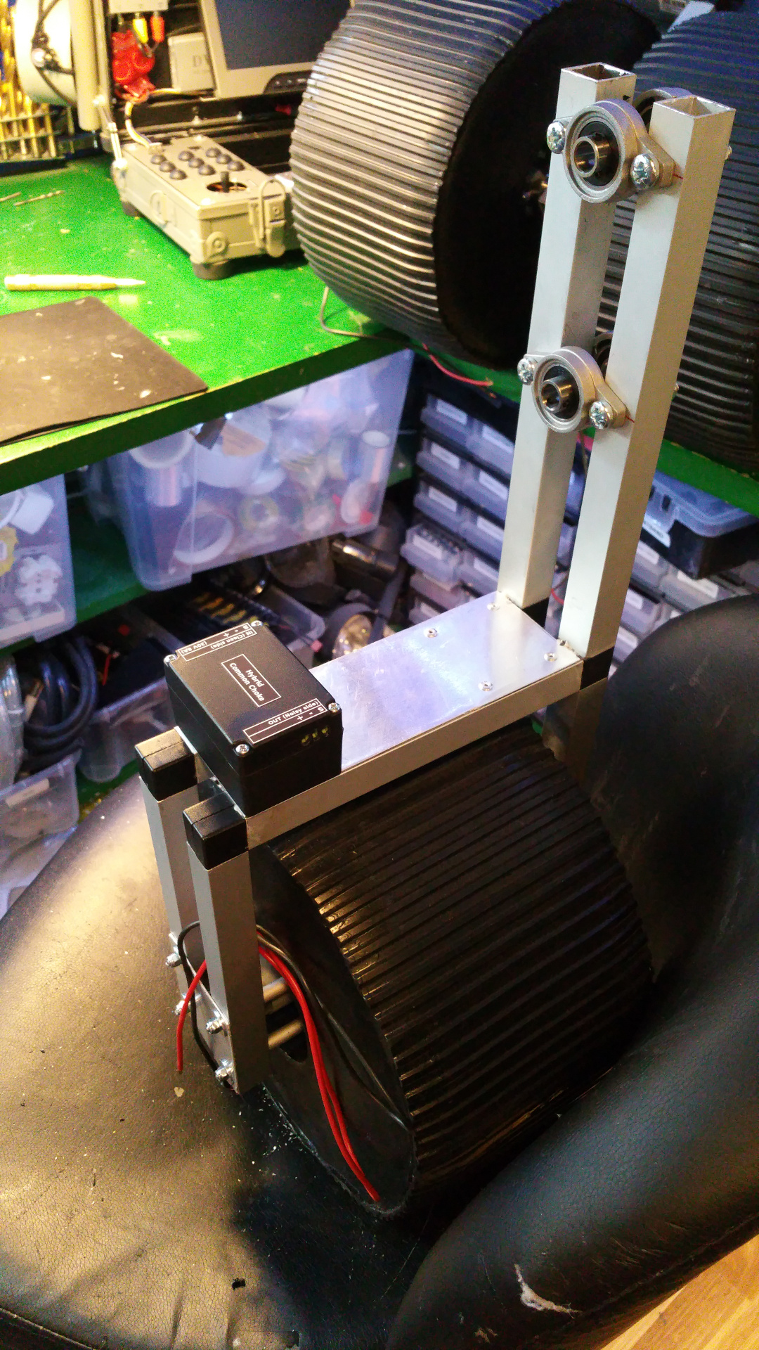
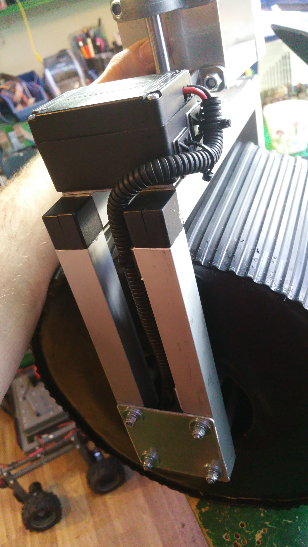
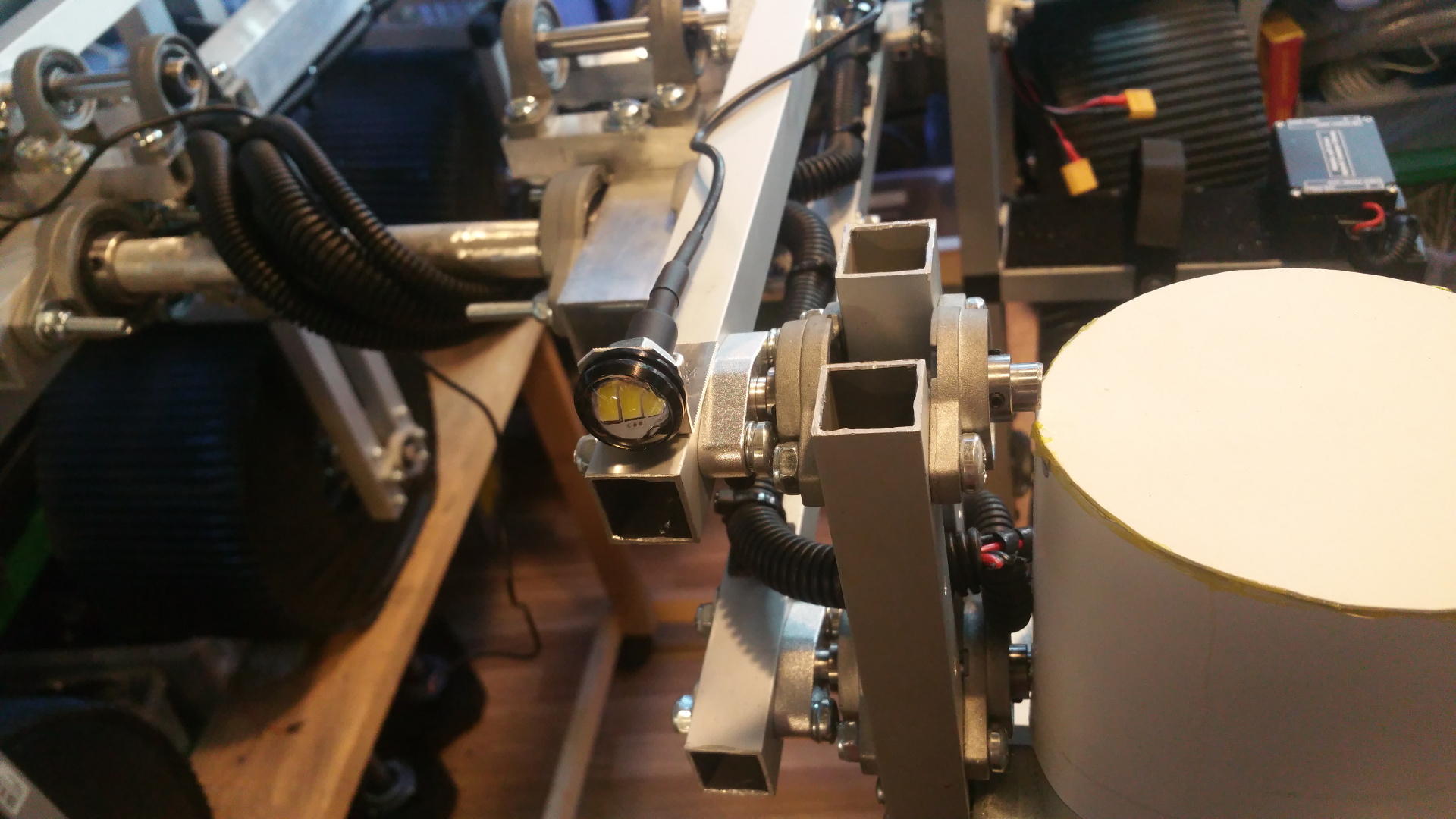
11. Connect wheel/bogie and frame
Connect all the stuff.
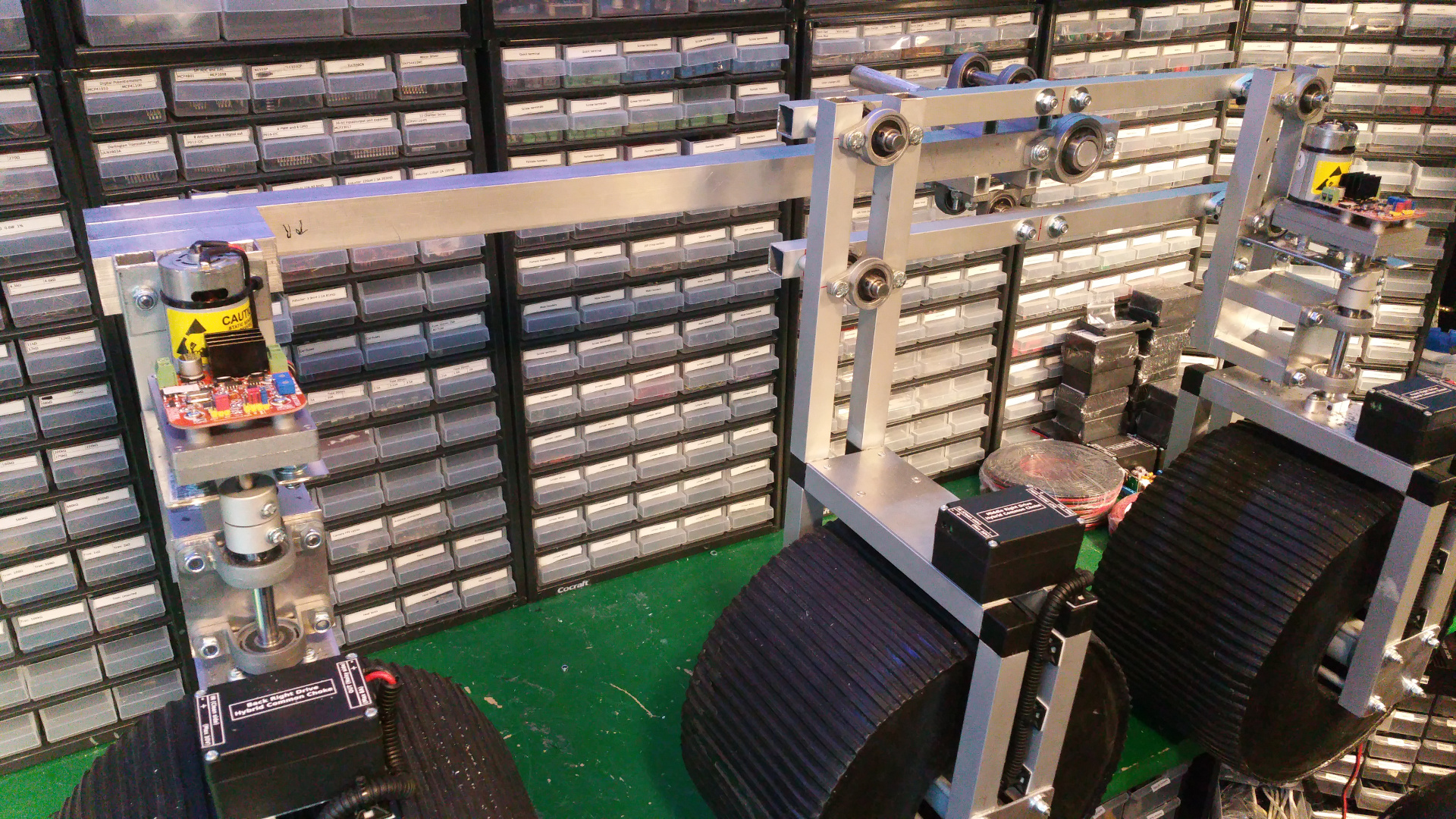
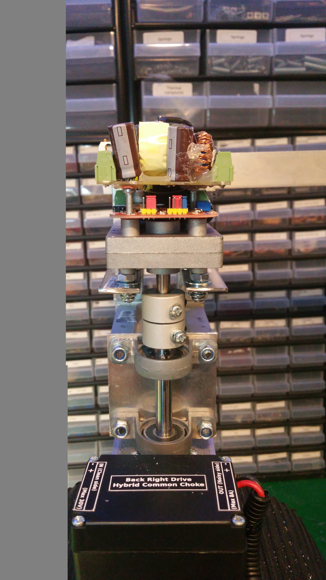
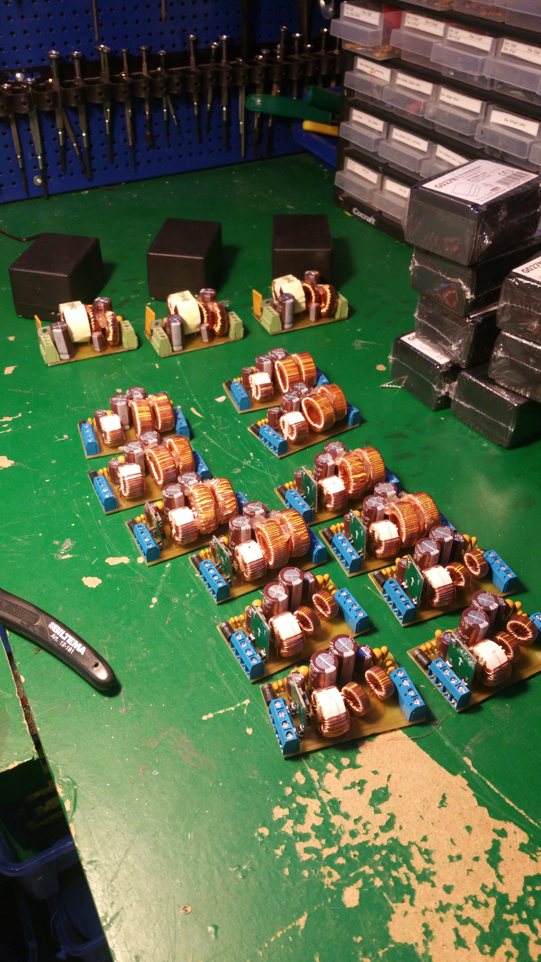
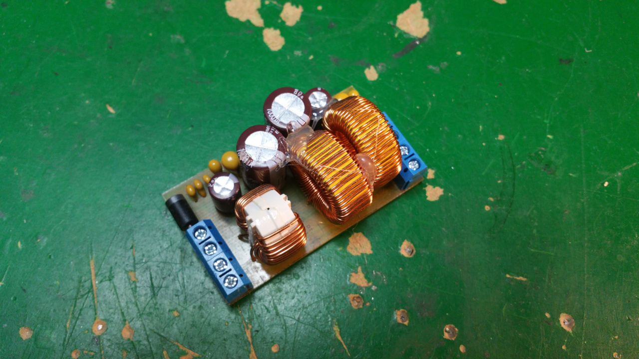
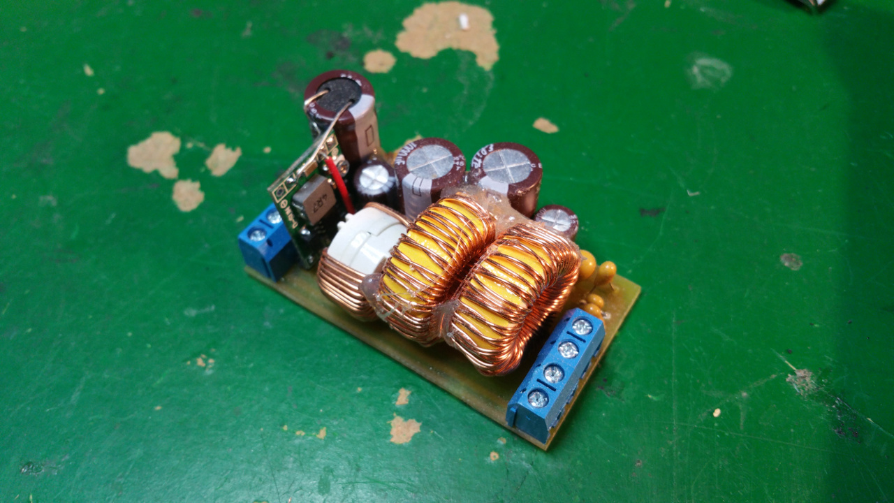
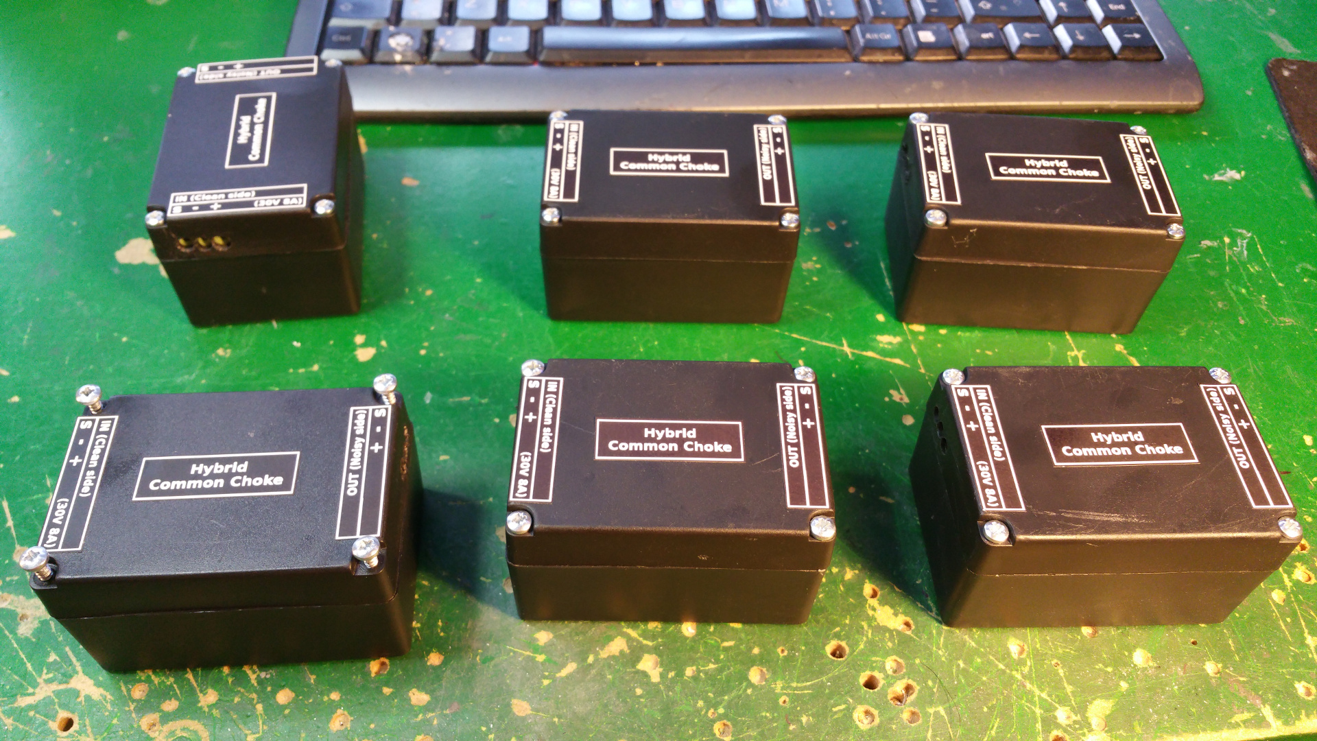
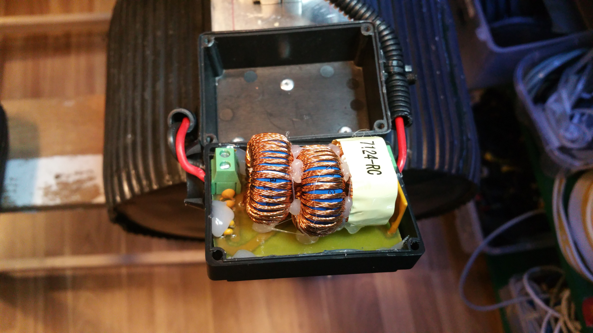
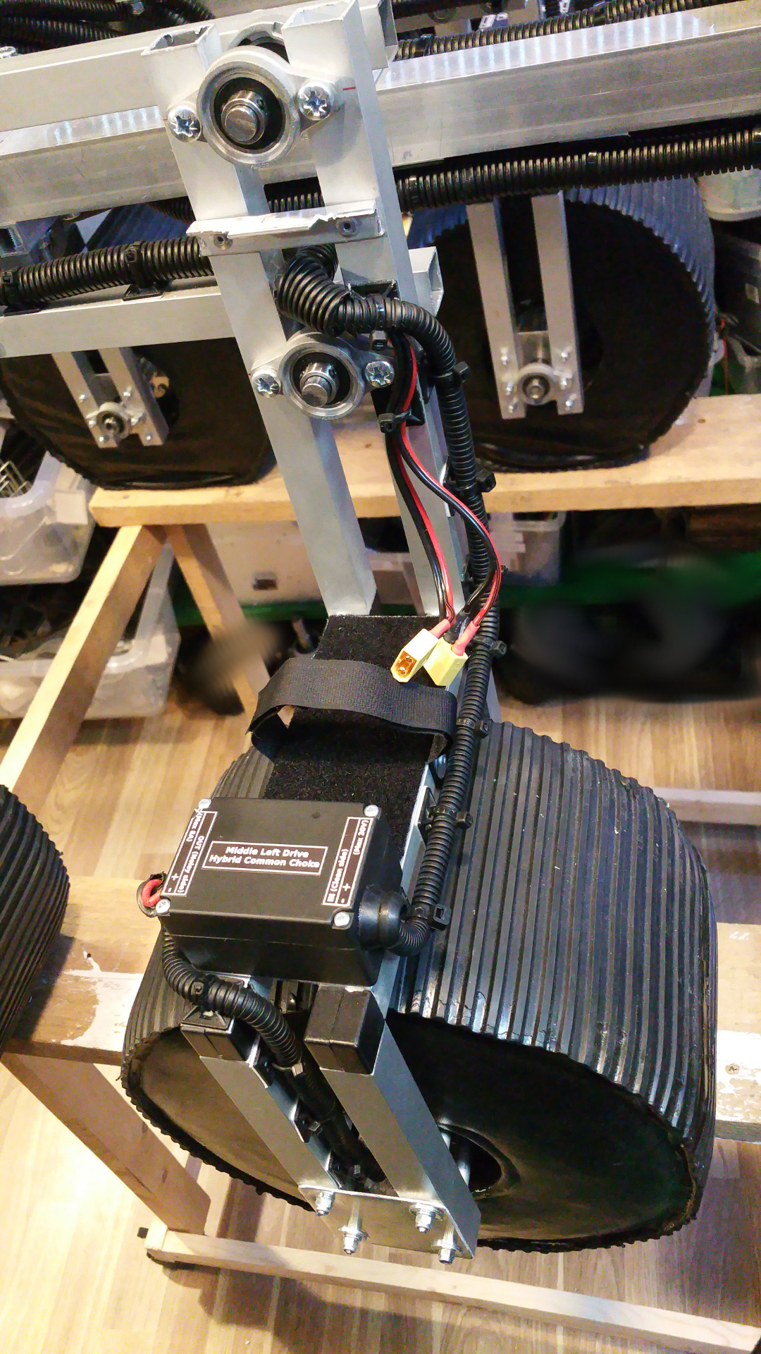
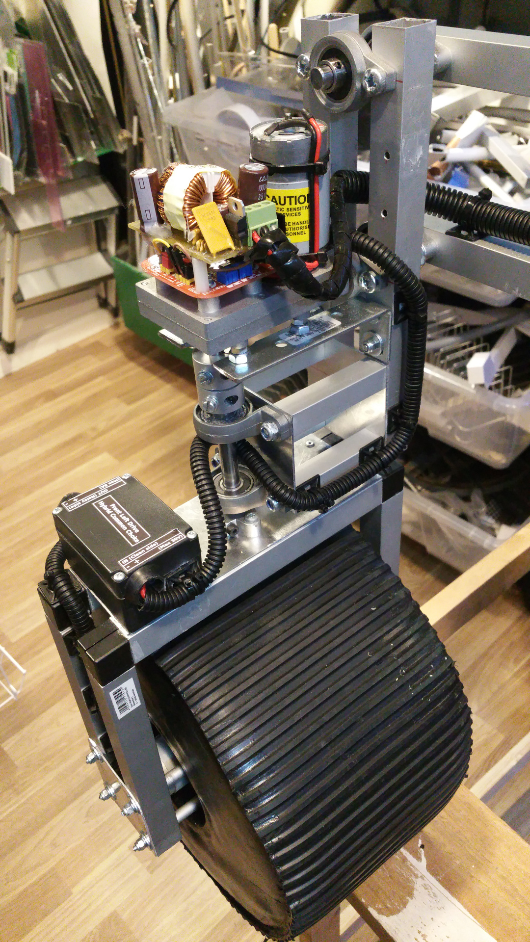
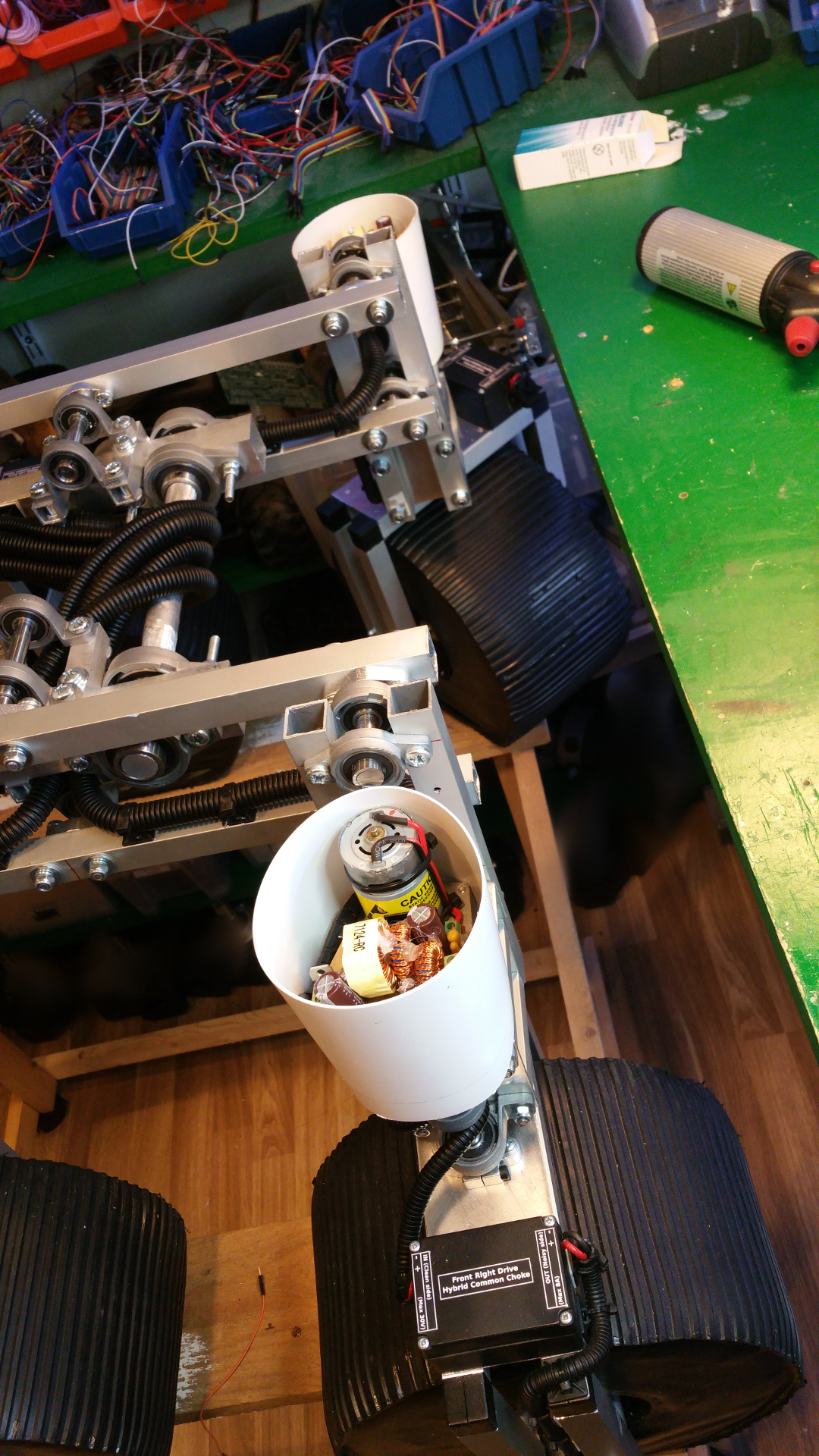
12. Hybrid Common Choke
All electronics on this rover should have Hybrid Common Choke.
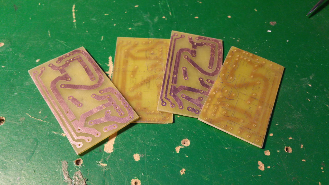
The Hybrid Common Choke i designed is probably totally overkill... they have both a common mode choke, differential mode choke and a lot of capacitors.
I designed three different types with the same base layout and components.
- Screw terminal
For easy connection of Power, GND and also extra connectors for example signals. - PTC fuse
Protect the circuit from over current. - Schottky diode
To keep the capacitor from discharging back into the source. -
Capacitors
Decoupling (Like a extra battery on high loads and quick load changes)
From 1nF to 1000uF (Probably overkill, but way not...) -
Common mode shoke
Filter out common mode noise (Interference that appears on both signal leads (+ and -)) -
Differential mode shoke for +
Filter noise on the power line -
Differential mode shoke for GND
Filter noise on the GND line.
This can cause problems so you can bypass them by solder on some places on the board...
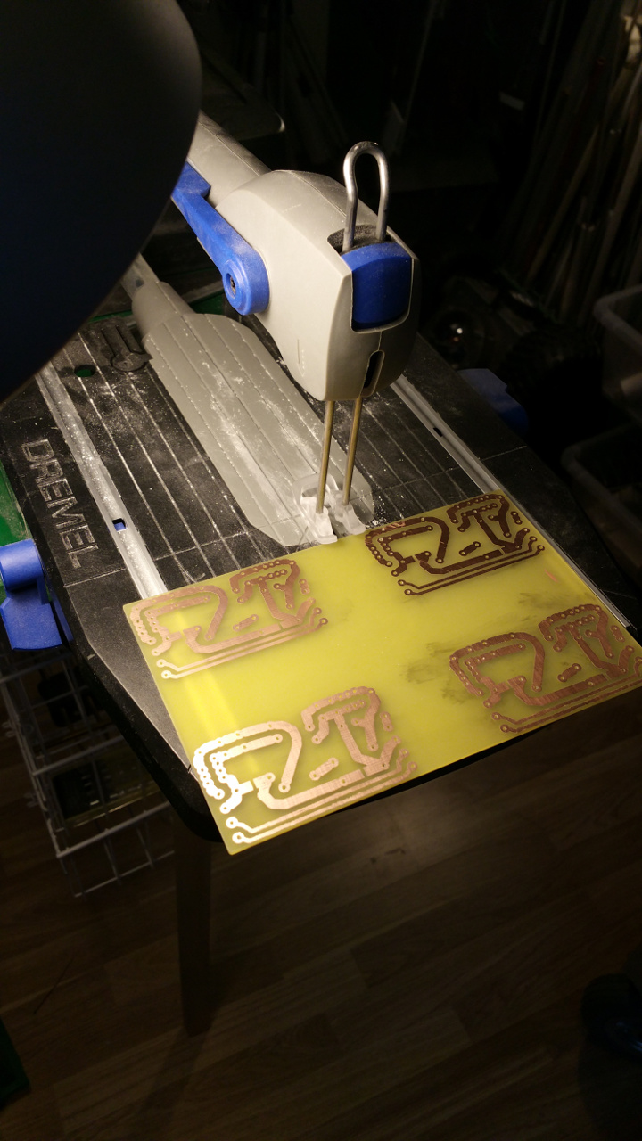

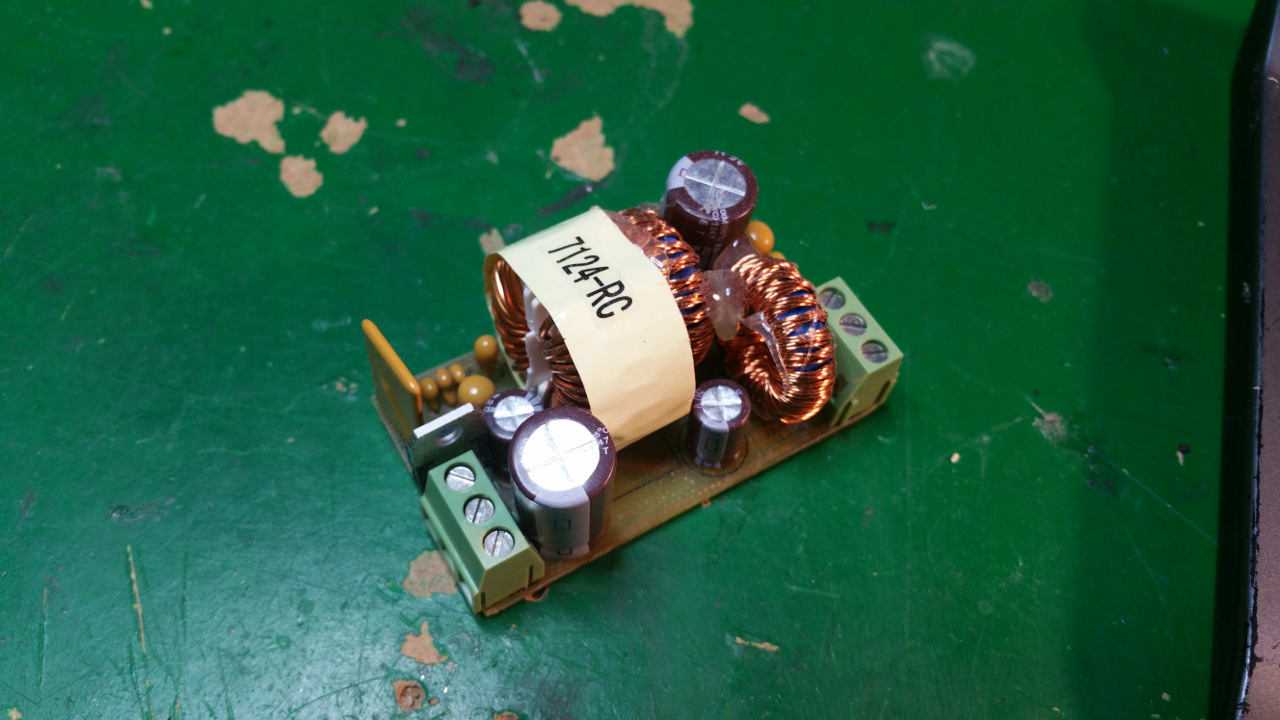
My Hybrid Common Choke factory :-)
I have tested them with my small oscilloscope (DSO Nano) when i drive a DC-motor and they seem to work but someone who is better than me on electronic might have a different opinion :-)
Without the filter i get a lot of nose and when i add the filter much less nose, but a simple LC-filter might work just as well.
Without the filter i get a lot of nose and when i add the filter much less nose, but a simple LC-filter might work just as well.
The three different types have the same base design but with various components to handle different loads and other stuff...
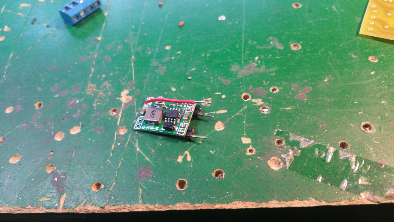
- Max 2A filter
This i will use to filter the FPV equipment and other stuff that can get power directly from the batteries.
In the PCB layout bellow i do not have any fuse, but i have add a PTC that hold 1.85A and trip at 3.7A
-
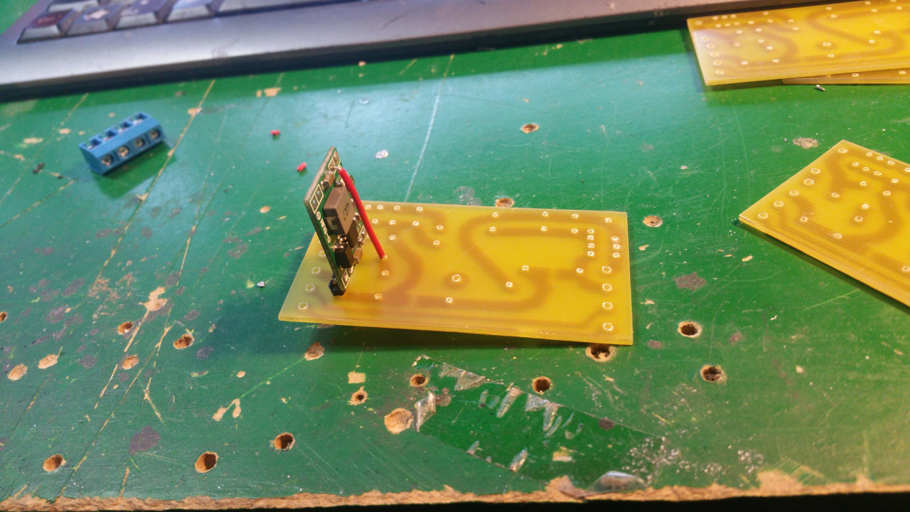
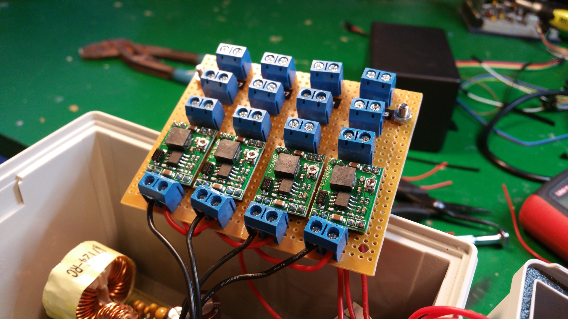
Max 2A filter with Buck converter
Power the Raspberry pi and other stuff that must have lover voltage.
In the PCB layout bellow i do not have any fuse, but i have add a PTC that hold 1.85A and trip at 3.7A
It is also a extra 1000uF capacitor on the output of the buck converter that you dont see in this PCB layout below.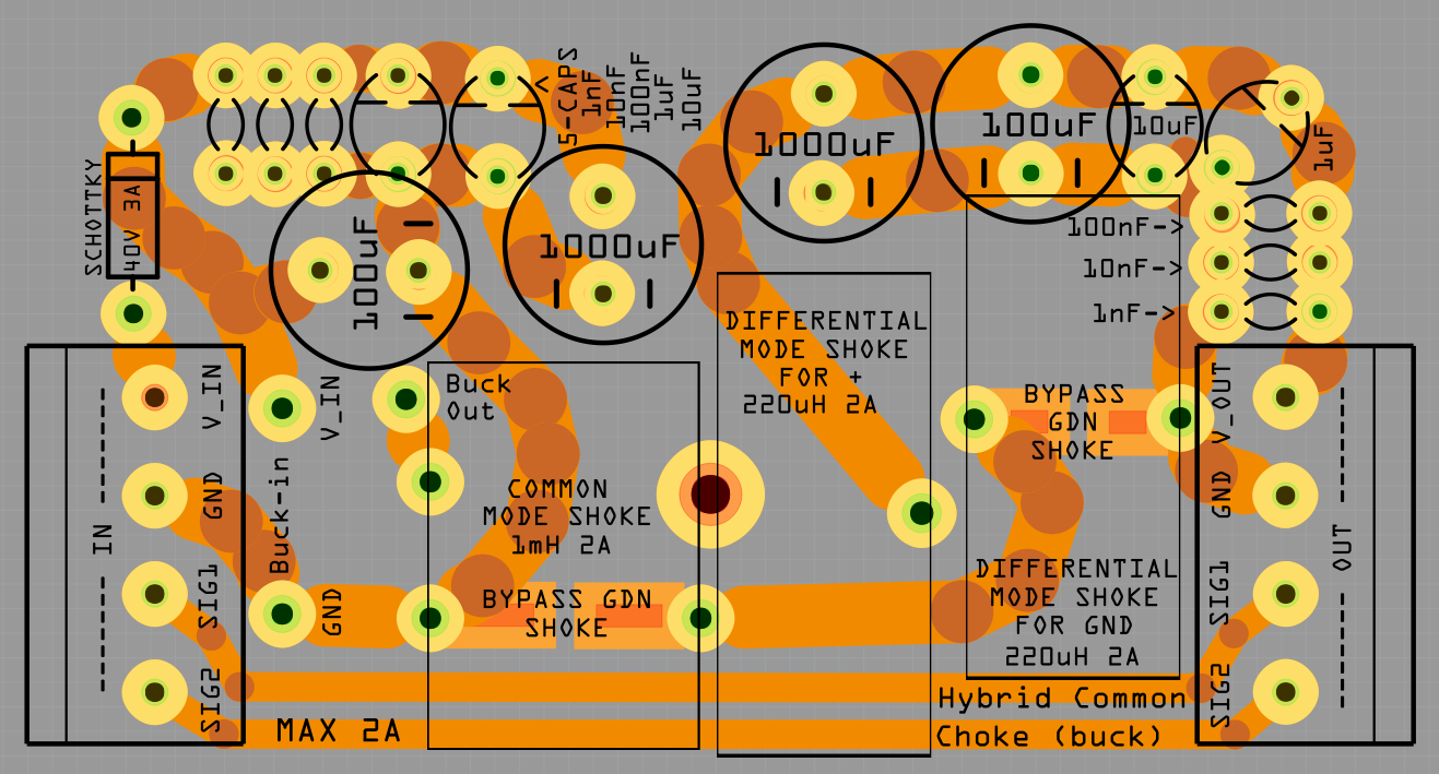
-
Max 8A filter
The DC motors need well regulated power and the LC-Filter will also reduce the interference from retching the rest of the system.
The PTC fuse will protect the motors from over current.
PTC fuse Hold: 5A Trip: 10A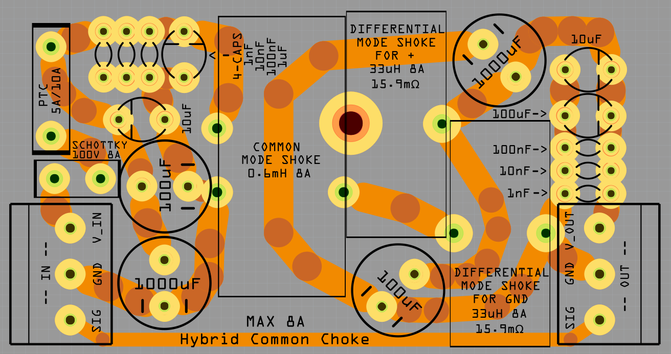
- The LC filter on the rover...
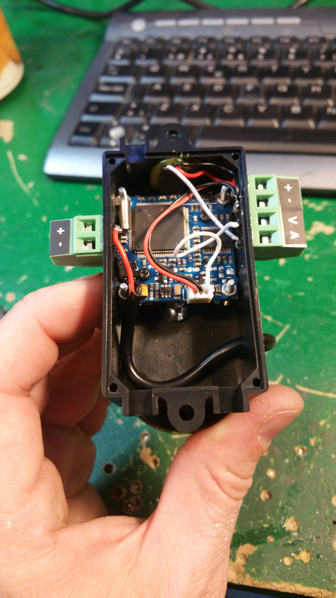
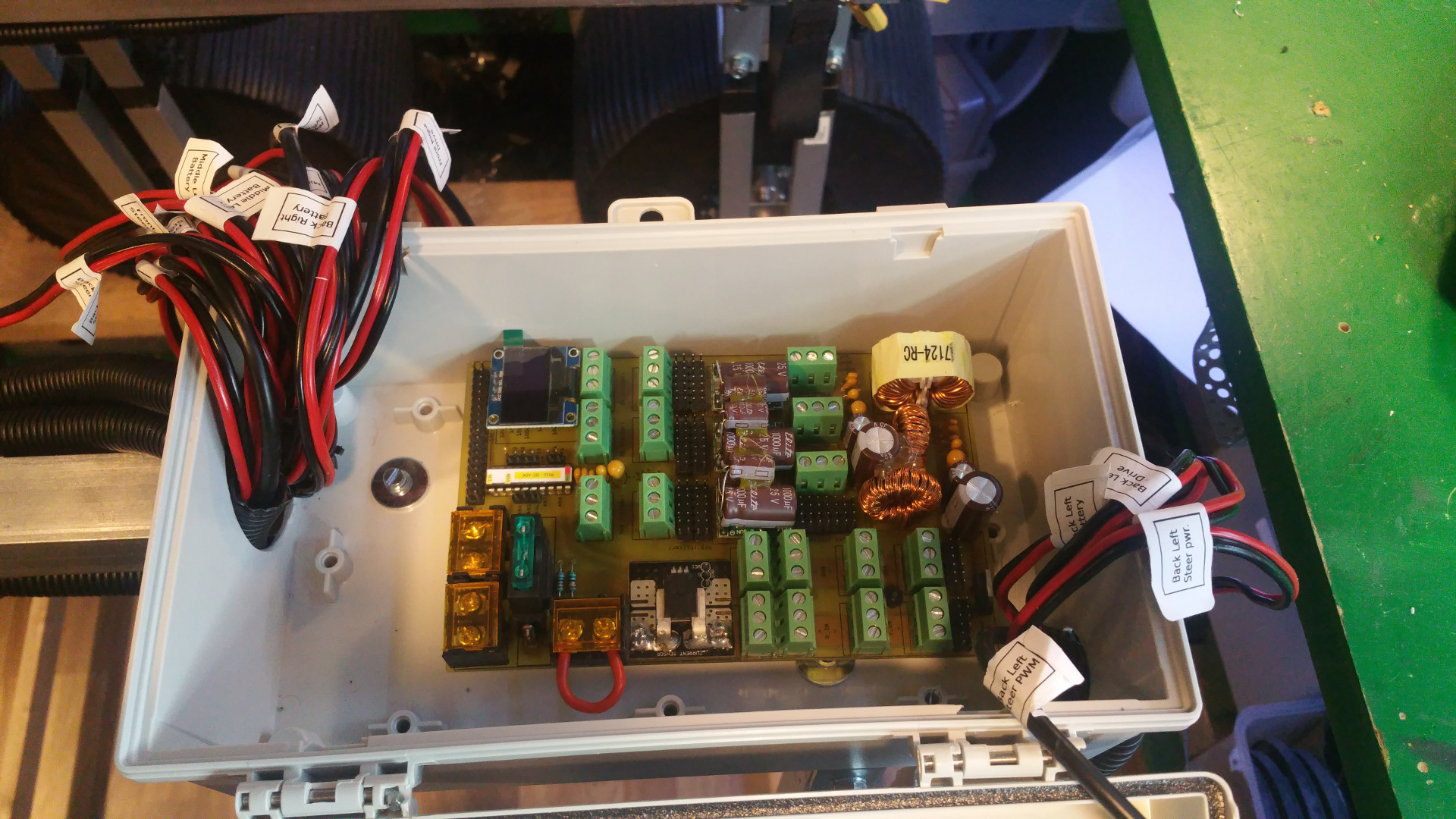
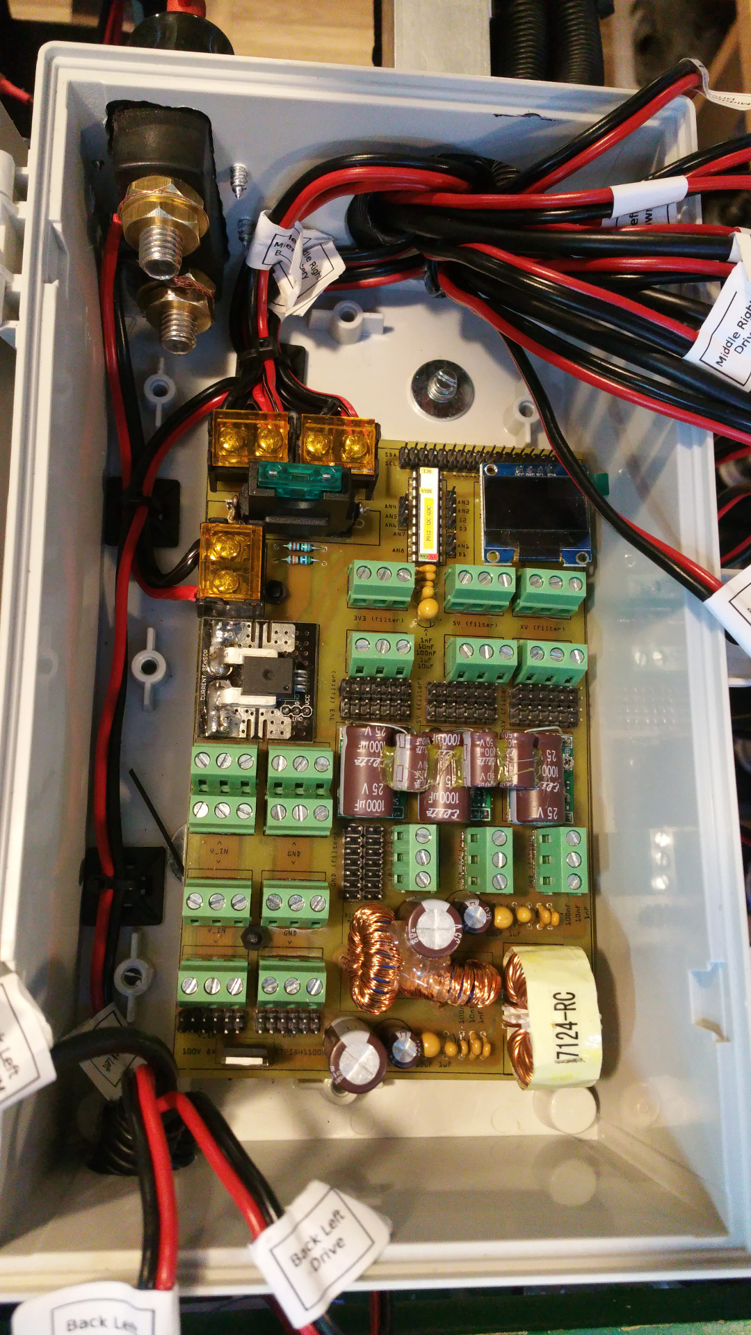
13. Power distribution board
I made my own power distribution board. Two screw terminals for power in and one for main power on/off.
It has 3.3V 5V and one more voltage...do not know what i will use it for now...
In the PCB layout bellow i do not have any PTC fuse on the buck converters, but i have add a PTC that hold 1.85A and trip at 3.7A on 3.3V, 5V and xV.
It has 3.3V 5V and one more voltage...do not know what i will use it for now...
In the PCB layout bellow i do not have any PTC fuse on the buck converters, but i have add a PTC that hold 1.85A and trip at 3.7A on 3.3V, 5V and xV.
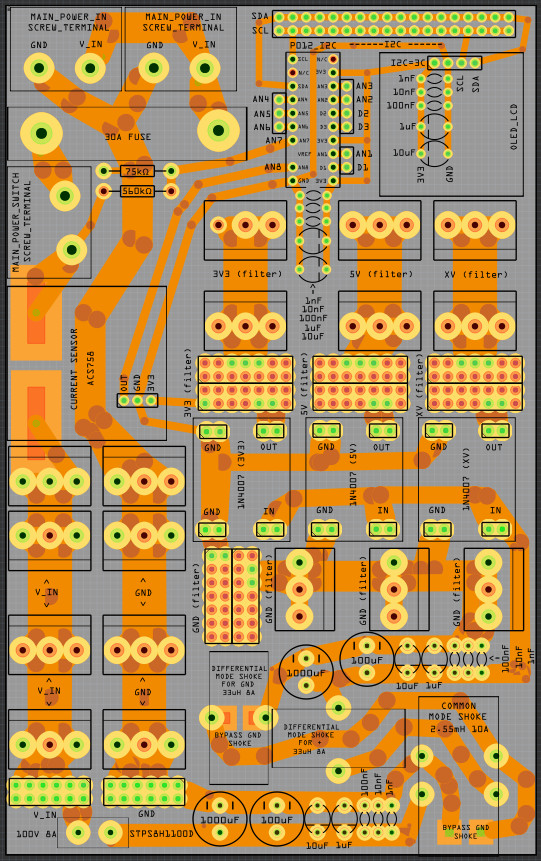

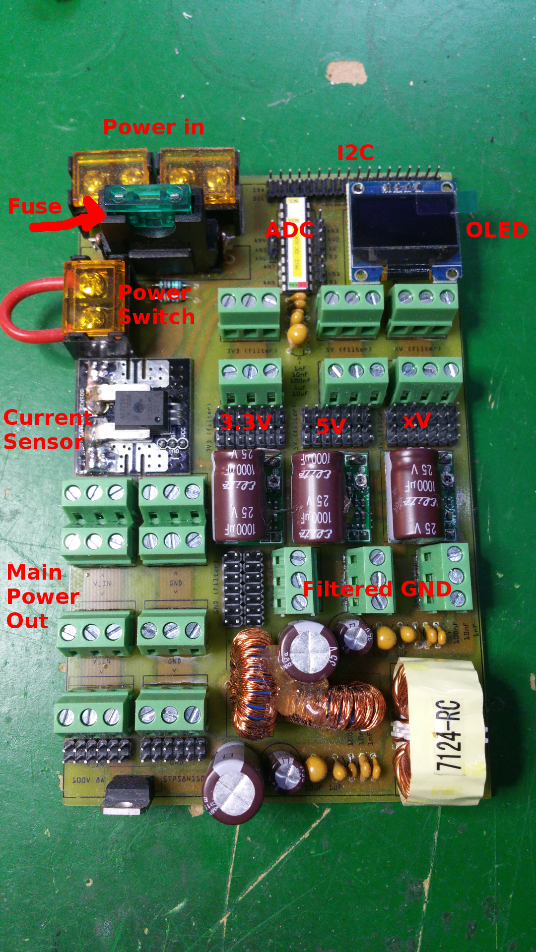
- Two screw terminals for main power in
- Main fuse (30A?)
- Screw terminal for main power switch
- Current sensor
- Voltage sensor
- Screw terminal and PINs for main power and GND
- Hybrid Common Choke for buck converters
- Filtered GND
- PTC fuse on every buck converter (hold 1.6A and trip at 3.2A)
- 3.3V, 5V and one other voltage out.
- ADC PO12 (Read current and voltage)
- OLED LCD
- Lot of I2C pins
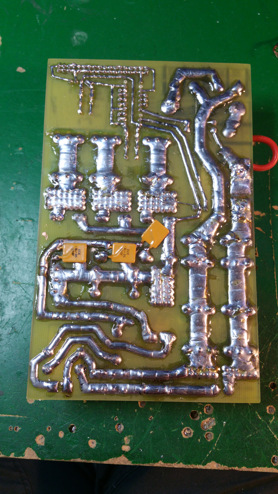
If you want more information on how tot do this...
- First print out the layout on a photo paper for a inkjet printer.
Some papers do not work, but the one i found works great.
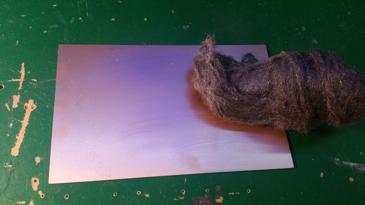
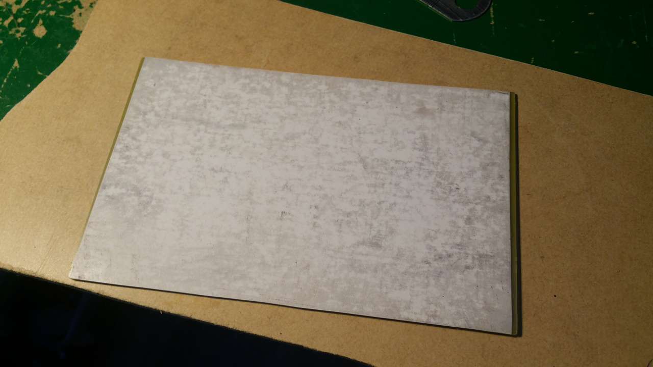
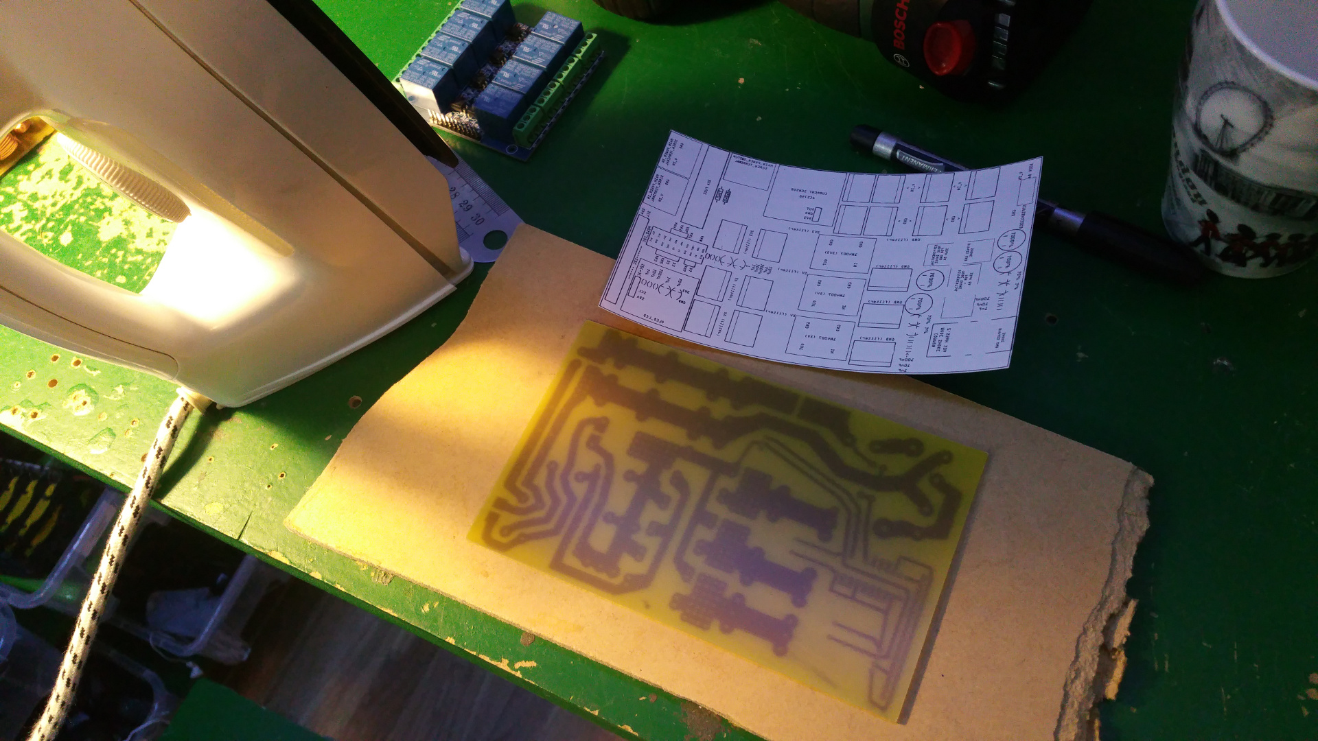
Roughen the copper side of the PCB steel wool.
Then place the paper with the ink down to the copper and iron on highest heat for about 5 minutes

- Peel of the paper, with the paper i use is it simple but other paper can stick and you may have to soak it.
If some of the ink don't transfer to the pcb, use a ink pen to fill in the gaps.
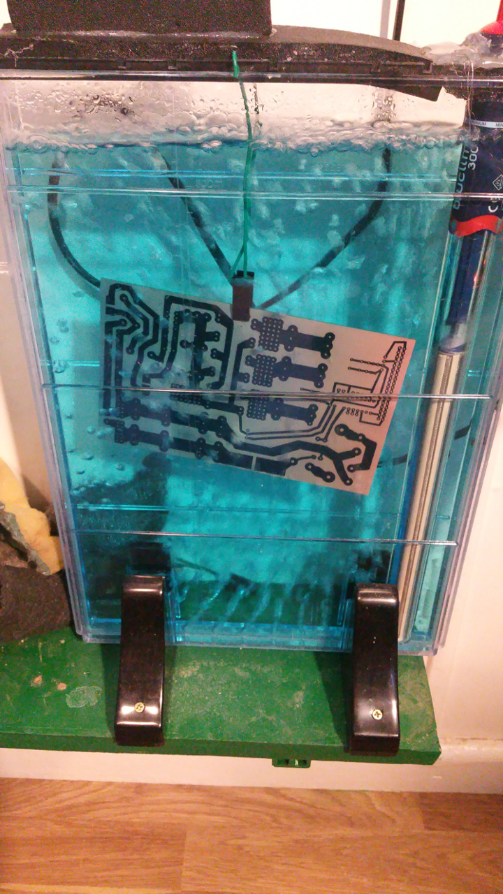
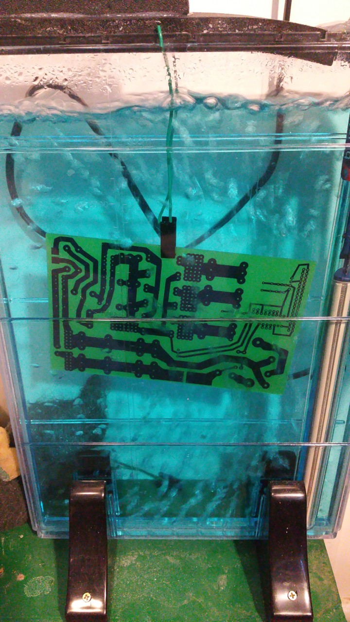
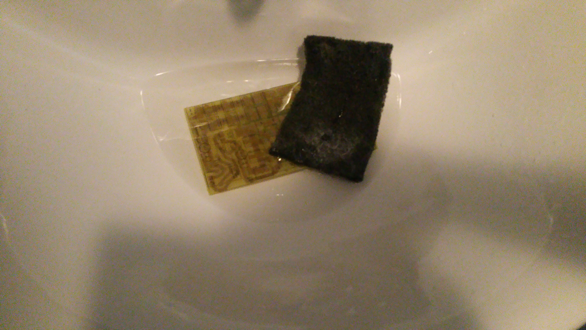
- Then put the pcb in the etch solution and wait for the copper to dissolve.
- Then clean of the ink with some acetone.


- Now it is time to transfer the text on the top side of the PCB.
Print it like before and iron it to the top side.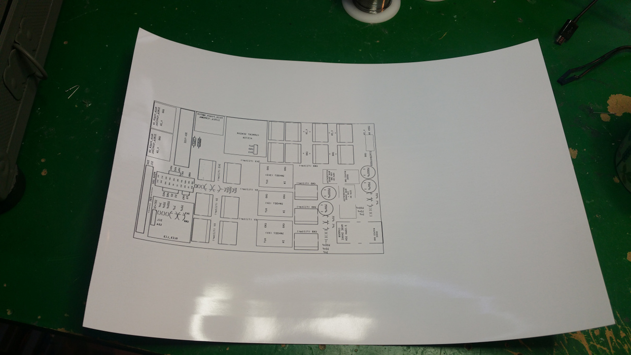
- It usually is harder to peel this of and you probably must scrub it gently to remote the white layer...


- The last think is the drill the holes, then you can solder the components...


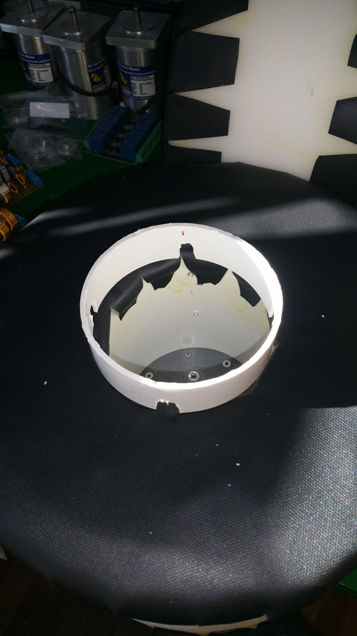
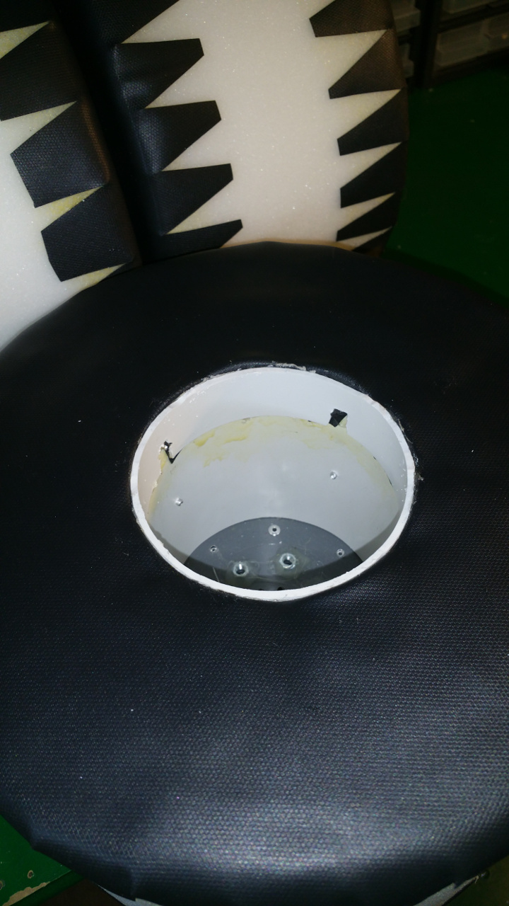
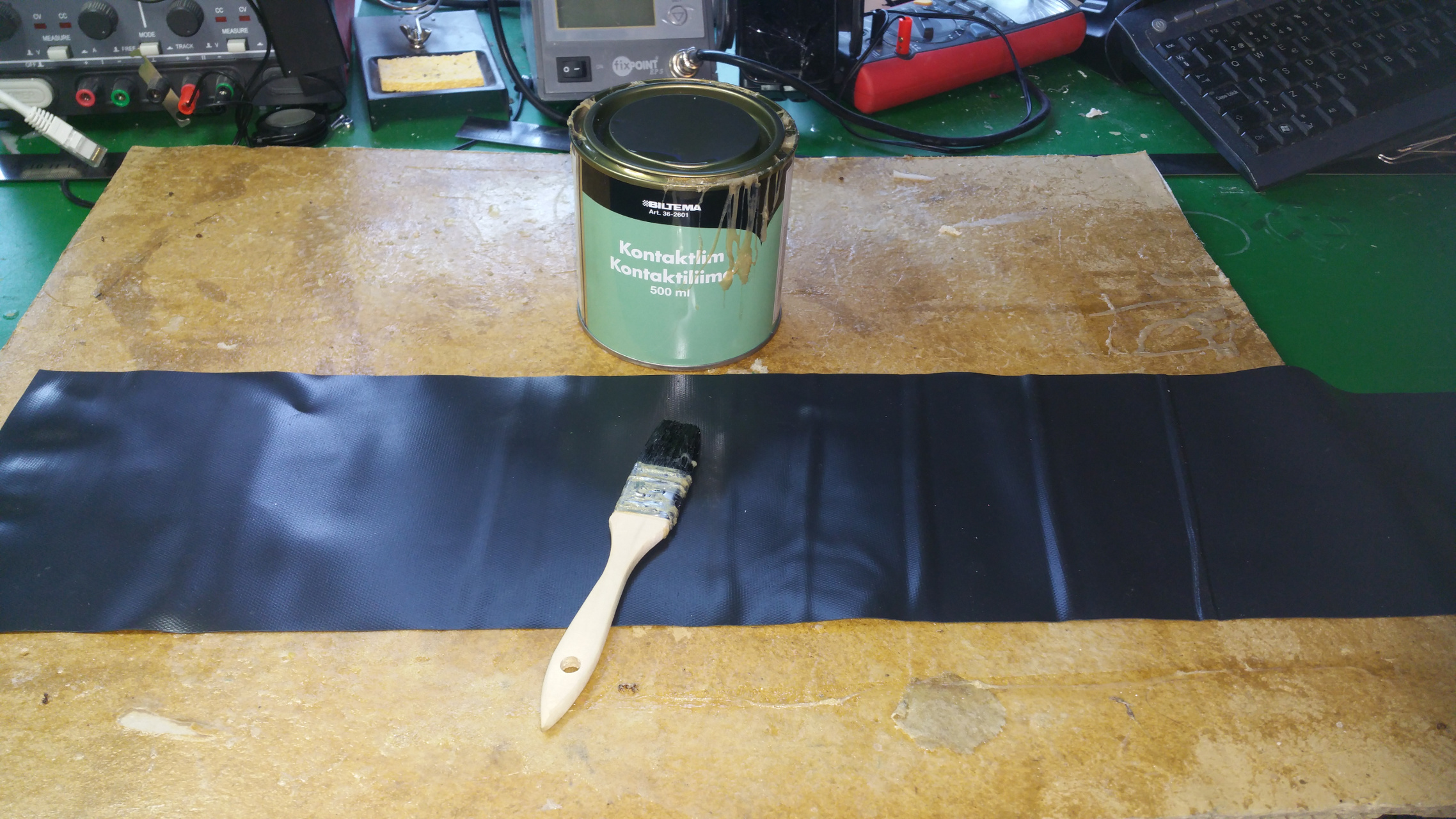
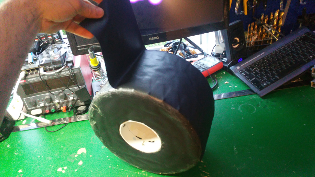
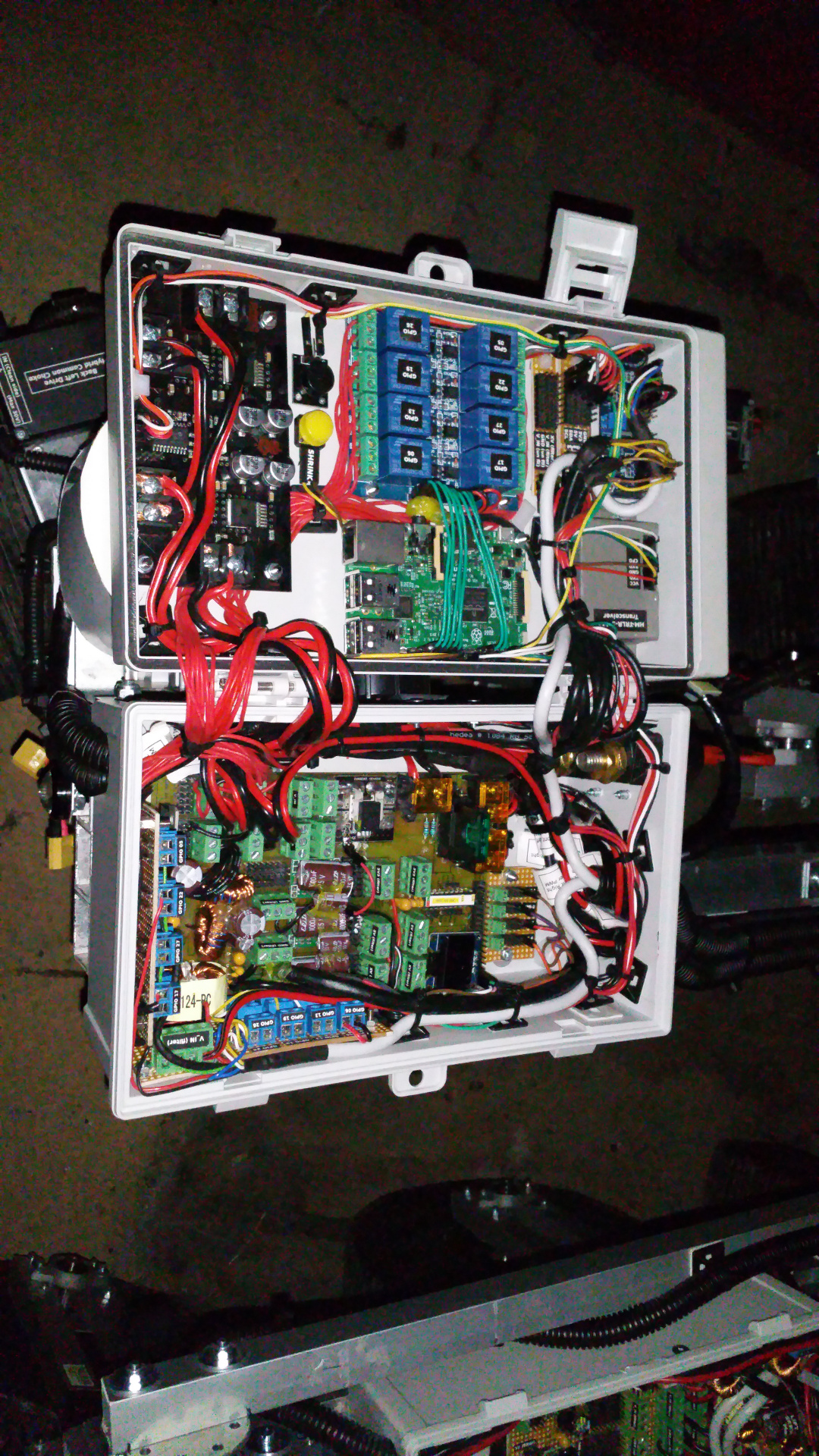
15. Wiring
-
All cables in protective tubes.
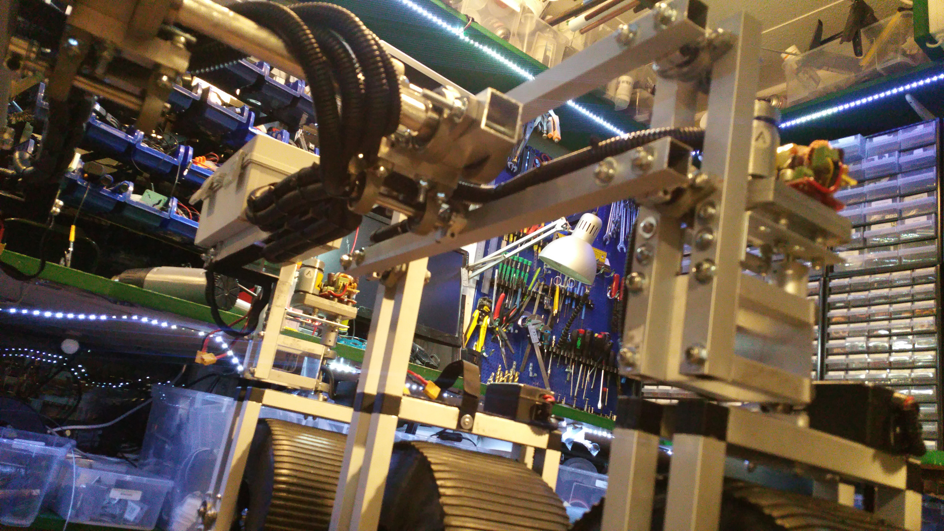
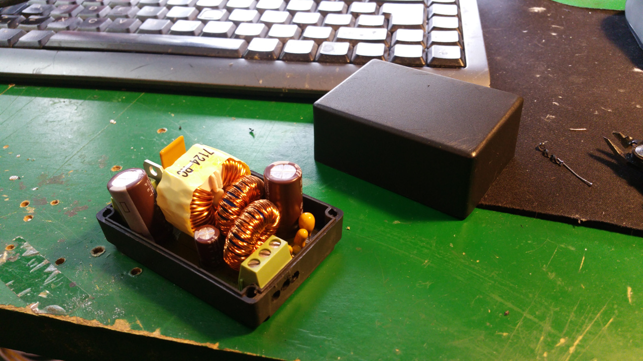
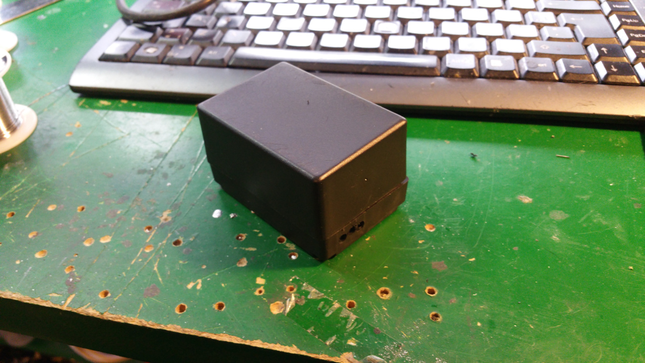
- Box for electronic
- Main power on

- Motor, relay, servo controller and the tranceiver.
The second picture is buck converters for the relay to power light and other stuff
- The two boxes with all the wiring and electronic

- Box with speakers and amplifier

- Enclosure for the steer servos and you can also see the speaker box...

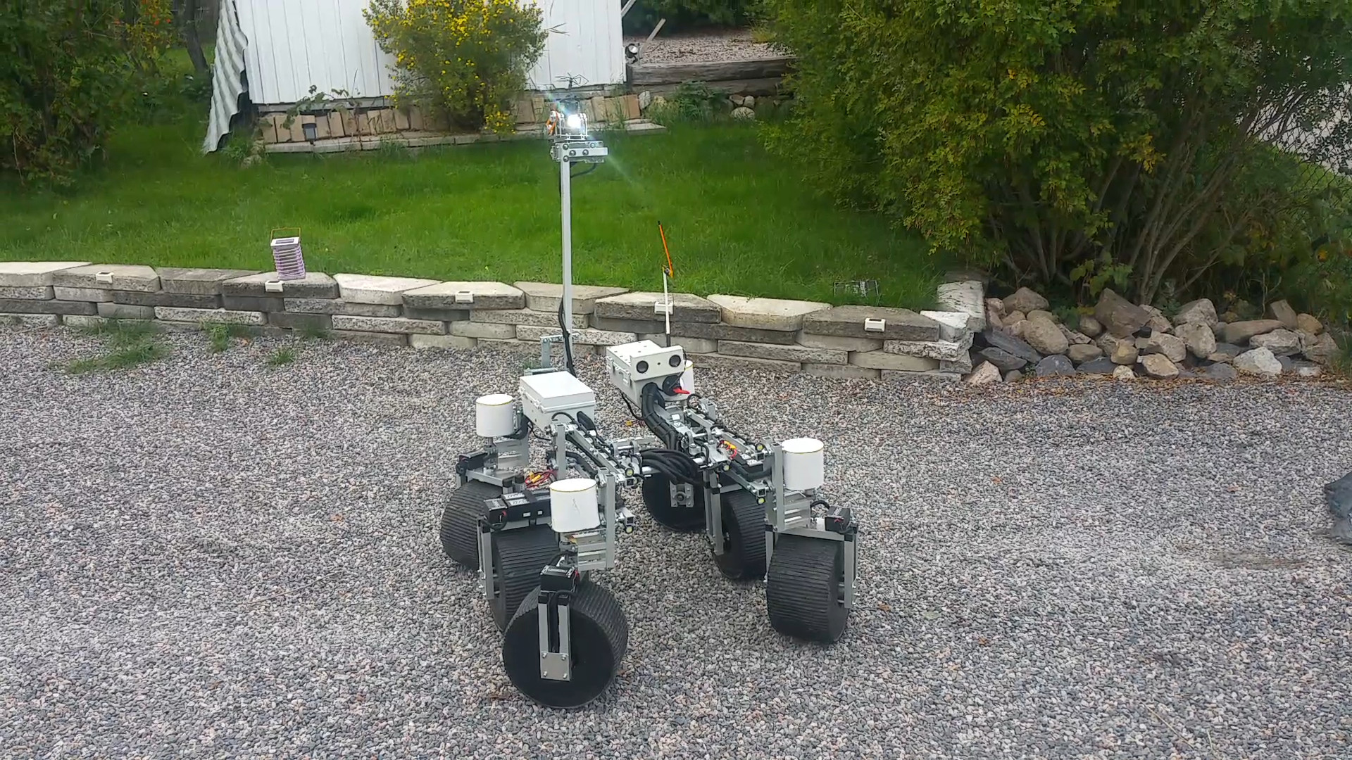
- The lighting
FPV offroad rover
- CPU: Raspberry Pi
- Operating system: Steelsquid Kiss OS (raspbian)
- Programming language: Python
- Sensors / input devices: video camera
- Target environment: outdoor
This is a companion discussion topic for the original entry at https://community.robotshop.com/robots/show/squidsscout-fpv-rover

