

Encouraged by a comment to RobotFreak's rendition of a SpurtBot, I am trying to build one too. I hope to make it as cheap as possible, because the goal it to bring materials to make a bunch of them to MakerFaire NYC.
If you want to build a SpurtBot, try these instructions.
LDR SpurtBot
Materials:
- Bearings: I'm using bearings scrounged from old inline skates that I got for free/cheap. Some required some cleanup, but I found instructions for removing and cleaning them on the Internet. Yea, Google.
- Bands/tires: Using the necks cut off of latex balloons.
- Popsicle/craft sticks: I have a big box of these I picked up for about $1 at a garage sale. They're very handy.
- Motors: Using a couple I got from Hobby Engineering for the prototype. They work OK at 3V, which is key. Motors too fast and not enough torque. Ordered a selection of motors from Jameco to see what works. The Jameco Reliapro PC-130F-12240 seems to be OK.
- Batteries: Using 2 AA alkaline's in a battery holder scrounged from a solar lawn light. Need to buy a bunch of these.
- LDR: Will use some I have on hand. I'll have to find ones with good values and buy a bunch.
- Transistor: I have a bunch of pn2222a TIP120 transistors, which should do the trick (the pn2222a didn't have enough gain).
Testing:
Seems to work OK in a well lit room. It requires some fussing and fine tuning with the position of the LDR. The results are workable, though the bot sometimes turns too sharply and misses parts of the line, or misses the line and drives past it. Still tuning.
This version doesn't follow the line very well. It tends to turn too far and jump off the line.
QRD SpurtBot
This version uses a QRD-1114 reflective sensor instead of the CNY70.
Here's the schematic. Click for a bigger copy.

Here's my notes on the build layout, taken from my Maker's Notebook. Click for a bigger copy.

Materials:
- Bearings: ABEC-5 bearings from inline skates
- Bands/tires: Using heavier duty 'punching balloon' for the tires.
- Popsicle/craft sticks
- 2 inches of 5/16 inch wooden dowel
- Motors: 3VDC, Jency Motor ST130-12240-38, Jenco part # 154915
- Batteries: 2xAA alkalines
- QRD-1114 reflective sensor
- Transistor: bc337
- Resistors: 33 50 to 85 ohms for IR emitter; 10k ohm for pull-down on pin 2 of the QRD-1114, 1.2k ohm on the base of the transistor.
- Battery holder: for 2xAA batteries
Build:
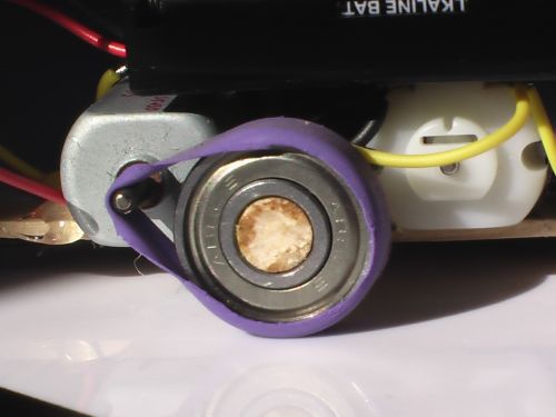
Here's a closeup of the right motor shaft. The shaft thickness is increased with three layers of heat shrink shrink. I rolled back the purple tire band so you can see the shaft better.
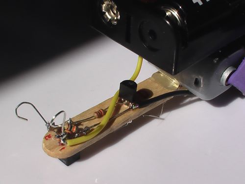
Here's a closeup of the electronic components on top of the SpurtBot. You can barely see that there are two resistors mounted cross-wise between the leads of the QRD-1114 at the head. R1 (refer to the schematic) is the 33 ohm current limiting resistor, which is on the bottom. R3 is on top mounted between 2 and 4 of the QRD-1114.
R2 is running from pin 3 of the QRD-1114 to the base of the bc337 transistor.
I curled the two front leads of the QRD-1114 around to look like antennae.
Testing:
Seems to work OK. It reacts a bit slowly, so I needed to use 3 widths of 3/4 black electrical tape for the track.
Batteries seem to run down pretty quickly, but it keeps going (just a bit slower) for quite a while. With fresh batteries (3.2V), it is too fast and often misses the track. It actually works better as the batteries get a little low, since it is moving slower. However, once the batteries get below about 2.8V, it begins to misbehave.
I'm tried shifting the battery holder a little more forward, to change the center of gravity. The bot tended to "pop a wheelie" sometimes, was affecting its line following capabilities. Shifting the weight forward worked great!
I tested to see how long it lasts with brand new batteries. Starting with 3.2V reading on the batteries, the robot ran very well for 20 minutes, and acceptably well for another 5-10 minutes. The batteries read about 2.9V by the time it started misbehaving.
I think a 20-30 minute duration for continuous use is acceptable. I think we have a winner.
Operation is much more reliable than with the LDR version. The video shows this version of the SpurtBot.
Variations:
Jameco only had 16 of the motors I wanted; the rest were on back order until October. That was going to be too later for MakerFaire and another event I need to prep for. So I tested the motors on the LDR version of the SpurtBot described at the top of this article. I left the TIP120 in place, but swapped out the LDR for another QRD-1114. I also eliminated the 10k pull-down resistor and the 1.2k base resistor. The circuit worked fine!
Unfortunately, those motors, while still cheap, were twice the cost of the ones I wanted. Since I'm buying in quantities, it makes a big difference. I had a few other motors from Jameco, so I tried a likely candidate, the Mabuchi Motor FK-260SA-10400. It's much slower at 3V than the original, but it works great, and it was even cheaper than the motor I started with. So I put in my order and will hopefully receive them in time.
SpurtBot for MakerFaire
NOTE: Detailed build instructions can be found here.
Here's the design I'm going with for MakerFaire.

Materials:
- (2) Bearings: Bearings from inline skates (Search YouTube for vids on how to remove and clean them.)
- (1) Balloon for Bands/tires: Using heavier duty 'punching balloon' for the tires.
- (1) Popsicle/craft stick: I like these nice color ones, but use whatever you like.
- 2 inches of 5/16 inch wooden dowel: Take the bearings with you and test for fit. The dowel should fit snugly.
- (2) Motors: 3VDC, Jency Motor ST130-12240-38, Jenco part # 154915 or Mabuchi FK-260SA-10400, Jenco part # 2081908
- (2) Batteries: AA alkalines
- (1) QRD-1114 reflective sensor
- (1) Transistor: bc337
- (1) Resistor: 50 to 85 ohms for IR emitter
- (1) Battery holder: for 2xAA batteries
Tools:
- Hot glue gun and glue sticks
- Soldering iron and solder
- Sharp sissors for cutting balloon and shrink wrap
- Heat shrink in several small diameters (1/16 inch, 3/32 inch and 1/8 inch should be good.)
- Lighter or other heat source for the shrink wrap.
- Wire strippers and cutters.
Notes on Motor Selection
I tried several different motors before finding good ones for this project. In case the motors I mention above are not available to you, here is what to look for.
- You need something that can operate at 3V. Many motors work fine over a range, be sure yours will work at 3V.
- It will be helpful to choose a motor with flat sides for mounting to the craft stick.
- Look for relatively low current demands, so your batteries will last a while.
- Important: Speed must not be too fast. Look for something in the range of 2500-8000 RPM when free running.
- Important: Get as much torque as you can for the speed. Something with at least 7 g-cm of torque should be fine.
Walks the line
- Actuators / output devices: 2 small DC hobby motors (3V)
- Control method: brainless line follower
- Power source: 2xAA alkaline
- Sensors / input devices: one LDR
- Target environment: indoor
This is a companion discussion topic for the original entry at https://community.robotshop.com/robots/show/spurtbot-for-kit
 Hope
Hope