Sensing servo feedback

Wiper = center wire of the

Wiper = center wire of the pot - the one you will read analog voltages from.

My guess is that the Lynxmotion SSC controls the speed the same way I suggested. You could email Jim (the owner) and find out. I believe he designed it himself.

Bringing back the pot’s ground wire was suggested by my teammate. He thinks resistance in the wires will introduce error into the analog reading, and that the analog ground will help. Honestly, he’s better than me at this stuff. :slight_smile:

Ah!

About the Wiper: Ah, I allready knew that actually. Seems I’m learning too much too fast and some of it just spills over :frowning:

And…quote: “he’s better than me at this stuff”. Then he must be pretty damned good :wink: Seriously, you’ve been an ENORMOUS help. For some reason your explanations just seem to pan out to me, which isn’t the case with everybody.

Thanks again…

Cool :slight_smile:

Nice to hear from someone who actually used one of these things (shunt resistors). However I’m just starting to read circuit diagrams, I’m still not that good at it and the one you linked to is particularly confusing. Couldn’t make any sense of it.

Basically what I need to figure out is:

1) What kind of shunt resistor to buy. I need one that measures from 0 to 1 Amp running 5 Volts.

2) Where to place it in my circuit. Eg. before or after the servo which current draw I’m measuring and how to connect it to my Arduino. I presume one wire goes to an analog in and another to the Arduino ground (and perhaps a 3rd to the Arduino 5V)?


I haven’t had much luck finding a resouce that makes this clear, but here is a simple diagram (from this page):

00165.png

I presume my Arduino will act as the voltmeter, but I'm still not sure how to connect it. The volmeter's - would be the Arduino ground and the + would be the analog in perhaps? That seems a bit weird though?! Besides all the shunt resistors I've seen look like this:

shunt-resistor-of-electricity-meter.jpg

As you can see they have 3 wires. Not 2 like in the diagram I posted (as well as other diagrams I've seen)?!

Or perhaps I don't need a "special" shunt resistor like that? Could I just do it with a "normal" resistor?


Thanks for the input...

Aniss

PS: Nice robotic arm :) But doesn't it need a gripper or something? What do you plan to do with it?

I use a normal resistor at

I use a normal resistor at 0.1 ohm.

If it is 0-1 Amp, the voltage to measure is 0-0.1 Volt. Just use an op amp to amplify the voltage to 0-4 volt and fed the amplified signal to the ADC input.


The robot arm is a chess playing robot with vision:

https://www.robotshop.com/letsmakerobots/node/2429

You can also take a look on

You can also take a look on this book:

http://books.google.com/books?id=jlvlZrAb92oC&pg=PA326&lpg=PA326&dq=Building+robot+driving+chain&source=bl&ots=ywM4GjD5VO&sig=z-b3ZZI9pTvwEMvCpW5_QqQviOY&hl=en&ei=FEuvSvDAO9aDkAW6ksGWBg&sa=X&oi=book_result&ct=result&resnum=1#v=onepage&q=shunt&f=false

page 224, it describes a very simple example there.

Servos

Hi Aniss1001,

Robotics is one place where the real world makes its presence felt.

The comment about careful processing, if you consider your leg when walking, the muscles exert a great force to start the leg moving forward, then the force drops off as the leg swings forward and then the forces reverse after the foot is planted, imagine the electrical signals.

The same for your servo, at the beginning of the step, the voltage will be high (large error = large V and I) the V and I drops as the targe position is neared, at the begining of movement the servo is basically stalled (current high).

Now then you put the communtator noise and other noise on top, the Voltage/Current signal needs be cleaned and then evaluated.

Thanks :slight_smile:

I checked the link (book) you provided. And this diagram I could read but it doesn’t seem that simple to me. There are 5 resistors + the op amp. Since I plan to measure the current draw of 12 servos that means 60 (!!) resistors + 12 op amps.

So please excuse me if these are silly questions:

1) The simple 1 resistor circuit I posted wouldn’t work (if I added an op amp)? Are 5 resistors necesary for my needs?

2) Would it be possible to use an analog muliplexer in combination with the current measuring circuit in such manner that I only need 1 such circuit to measure the current of 8 servos (or 16 depending on the no. of channels on the multiplexer)?


Thanks for your advice :slight_smile:

Aniss

PS: VERY impresive chess playing robot :expressionless: Especially the machine vision. I’ve been studying and playing with some machine vision myself. Mainly some motion detection and some neural net based object/facial recognition. So I’m curious: Which tecniques did you use to make it recognize the chess pieces?

If you want to monitor and

If you want to monitor and measure the current for 12 servos, may be u shall use current sensors (e.g. the one used by openservo, http://www.diodes.com/datasheets/ZXCT1009.pdf). I have no experience in multiplexer.

For the robot arm vision, I use opencv and some technique described here:

http://hk.myblog.yahoo.com/jw!afd6dGGRHBRkp2laqwk198fg/article?mid=462


BTW, if you want to measure the stress of a servo at any time by taking measure of the current it uses, you have to make sure the servo is not moving at the time of measurement. The reading of a moving servo is not useful in this case.

I would suggest you use a digital servo (e.g. with openservo) for your case. You can always read back the velocity, error, and other useful information from the servo to meet your need.


What?

I was definately NOT aware that I can’t measure the current while the servo is moving. In fact I thought that a servo didn’t use any current (or very little = standby) when it wasn’t moving.

Are you sure that is the case?

That pretty much changes everything. It may still be useful, but not for what I originally had in mind.


Again…thanks for your input

Exactly!

It would seem were ARE on the same page. And like I said I did consider that quite a bit. When I tell a servo to move I will allow it to have an abnormal current draw for the first few milliseconds (how many will depend on a test). It’s only if the the current draw doesn’t decline at the expected rate that I will assume something is wrong (=the servo is experiencing stress).

But since clcheunghk just informed me that I can ONLY measure the current while the servo ISN’T moving I’m not quite sure what to think anymore ?!

Sorry for the misleading

Sorry for the misleading english.

I mean that when a servo is moving, it is not very useful to measure the corresponding current it is using. Only when you believe the servo is stopped, a high value of current using indicates a "stress" on the servo.

So you may need to take the data together with the servo controller to make a clever guess on the stress levels on the servos.


I’ve made a video:

I’ve made a video:

http://www.youtube.com/watch?v=9RRb78VJUp0

The situation will be like this:

- when the robot is at rest, it takes about 0.25-0.35 Amp current.

- when the robot is moving, it takes about 0.35-1 Amp, on average. Note that you need to compute the average reading or otherwise there will be a lot of noise.

- when I bend the leg of the robot, some servo is under stress, the current usage is going up to 1.4 Amp.

Hope this can you help visualize your idea.

Very cool video and great
Very cool video and great explanation. Are these the HXT-12 servos?

PWM vs. PPM

To whom it may concern (perhaps FingerTech and Robotologist):

Our little discussion about whether a servo is controlled by PPM or PWM kinda bugged me, so I created a topic on the Arduino forum hoping to get a comment from the guy who wrote the comment I posted earlier. And I did. Here it is:

http://www.arduino.cc/cgi-bin/yabb2/YaBB.pl?num=1253149521/6#6


Aniss

Those are MG995 with my
Those are MG995 with my version of openservo. More information at https://www.robotshop.com/letsmakerobots/node/2423

Thanks again!
1st of all you’re english seems fine. Sorry if I gave you any other impression.

The reason I wrote “what?” was because you said…

“if you want to measure the stress of a servo at any time by taking measure of the current it uses, you have to make sure the servo is not moving at the time of measurement. The reading of a moving servo is not useful in this case.”

…And I was unaware that a servo even draws current while NOT moving. So I got confused. I still have very limited knowledge of servos.

My idea was to measure the current draw ONLY while the servo is moving. Like this: I tell the servo to move to a specific position. If something is blocking it’s movement then it stalls and I should be able to detect an abnormally high current draw, thus I would know that something is blocking it’s movement.

So I wanna ask you one more thing: in the video…is the current draw reaching 1.4A simply because you’re bending the leg OR because it’s trying to move at the same time (thus it is stalling)?

Sorry if my questions seem silly. I will off course be spending hours experimenting myself once I get my setup up and running…


Thanks again for all your input :slight_smile:

Aniss


PS: WOW! Your walking robot is even more impressive. I hope one day to be as skilled as you. Respect!!

>> And I was unaware that a

>> And I was unaware that a servo even draws current while NOT moving.

You are basically correct. The servo only draw a very little current when it is not moving when it is not under “stress”. i.e. the servo already move to the decided position.

>> So I wanna ask you one more thing: in the video…is the current draw reaching 1.4A simply because you’re bending the leg OR because it’s trying to move at the same time (thus it is stalling)?

When I bend it, the servo positions are shifted away from the original position, so it tries very hard to restall back…and thus a high current is measured.


>> PS: WOW! Your walking robot is even more impressive. I hope one day to be as skilled as you. Respect!!

Thank you ! I am also a beginner in robot building.

Pulse Width Modulation/shunt

Hello Aniss,

I am not sure why the confusion, but (typical) servos use Pulse Width Modulation, the width of the pulse is what controls the output position, Servos are typically very tolerant of variations in the pulse interval. Finger Tech provided a good description of PWM vs PPM. The only thing I did not like was the “Pulse Width Modulation has a fixed frequency and variable period” statement, normally the term period refers the duration of cyclic wave form, thus period = 1/frequency, but I think we know that finger Tech was refering to the “On period”. I have never seen a servo which uses PPM, that does not mean they don’t exist. One could successfully control a servo by providing a pulse train which is (control pulse) 20ms (control pulse) 20ms, this would keep the period within 25ms; so in this case the position of the pulse would vary but that is not what the servo looks at, in fact if the pulse is late this triggers a missing pulse detector, in this case the behaviour of the servo varies from manufacture to manufacture.

I thought I would add something on shunt resistors (sense resistors) there are two ways of using the shunt resistors, high side and low side, High side is where the resistor is on the posititive side of the load (motor), so as not to waste power it is important that the shunt resistor be of a reasonably low resistance so to make the signal useable we need to amplify it, the circuit below shows one way of doing this for high side sensing:

Highside.jpg

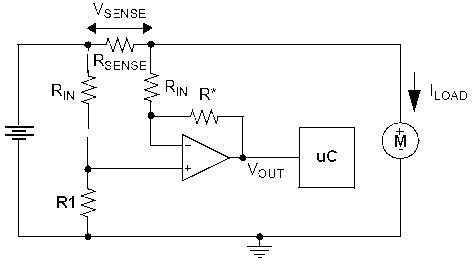
The uC is the microcontroller and is natually an Analog (A/D) port.

In this case Vout = Vsense x (R*/Rin) = Rsense x Iload x (R*/Rin)

[R1 = R*]

Now for the low side:

lowside.jpg

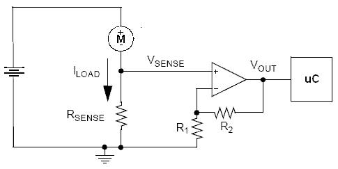
In this case Vout = Vsense x (1 + R2/R1) = Rsense x Iload x ( 1 + R2/R1)

The Opamps are just configured as fixed gain amplifiers.

Now the trap, the servo motors are reversable, so in one direction the shunt is on the low side and the other way the high side.

A couple of other issues is the motors are inductive loads and generate a back EMF when the current stops, this could be enough to cook the Opamps. Normal practice is to tie Vsense line to the +V and Gnd rails by REVERSE BIASed diodes.

You can also sense the "speed of the motor" using the comutator noise (little DC can motors typically consist of 3 windings which are turned off and on) in the Automotive industry this is the common tecnique used with such things as Window Winder Motors (i.e. detecting you head is in the window).

any way got to fly, I am late again....

If this is of any use I can write a little more.

best regards

cliff


Hi again

Well, the confusion originates from this article and the fact that several very knowledgable people (on the Arduino forum) believe that PPM is more appropriate than PWM for describing servo signals.

Here is (a part of) an explanation that I’m still trying to fully understand (copied from this thread):

PWM involves the modulation of a signals duty cycle. In controlling a servo, the duty cycle does not control the position of a servo. Servo position is controlled through modulating the on time of the pulse. Indeed it is possible to control a servo over its full range of movement by changing the on time but keeping the duty cycle constant. If servo control works perfectly well without changing the duty cycle then PWM modulation would not be the most appropriate term for the modulation used.

The terminology is confusing because servo control pulses do involve changing (modulating) the pulse width. And a subset of PWM can be used to emulate the modulation needed to control a servo. But its no more correct to say that this makes the servo signal PWM than it would be to say that an AC (Alternating Current) signal is PWM because PWM is capable of alternating (switching on and off) current. Indeed it is possible to emulate AC using PWM (along with a few passive components) but of course that doesn’t mean one should say that AC is PWM modulation.


Perhaps you will understand it better than me. I just understood what duty cycle means, but I’m still not clear on what the term modulation actually means…

And thanks for your thorough comments on the shunt resistor matter. I’ll get back to you on that when I’ve studied it some more…


Best wishes :slight_smile:

Aniss

OK

Just one last question…for now anyway :slight_smile:

Is the servo trying to restall back because your microcontroller is constantly telling it to do so, or simply because of the last command received?


Thanks