

This robot was started when i was at faculty of Mechanical engineering and mostly as a time to kill between studying. Then i made few seminars regarding the controllability of non-holonomous construction and after that it became my "project". I made my master Thesis on simulation model of this construction but i have never got the time and resurses to made it real. So after few years it came back on my table and i started to work on it when i get back from work ...
Basically it all started with Tamiya RC model which was bought to play around, but i got borred very fast and i started to modify it. Then i came idea to put another steering wheel option and of course idea to make it autonoumous. I made some modificaitons on construction and basically all that was left from original model was gear box.
Some of the parts was modelled in Catia and made either on faculty or at local CNC shops. Other parts was bought over e-bay and fitted. Electronics is made as modular construction where i buy bits and pieces around and assemble it on one of my own board which was designed to fit "perfectly" inside of construction.
At this very moment im concentrating on writing the fuzzy logic controller for the Bot. Also all of the programmings are made by me on Keil for ARM and manual control are done on iOS.
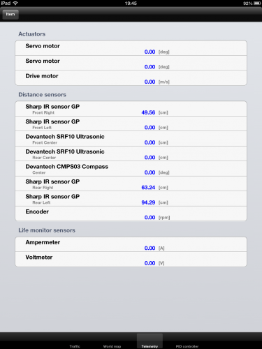
Live telemetry view on ipad. (at the moment not all sensors are functioning)
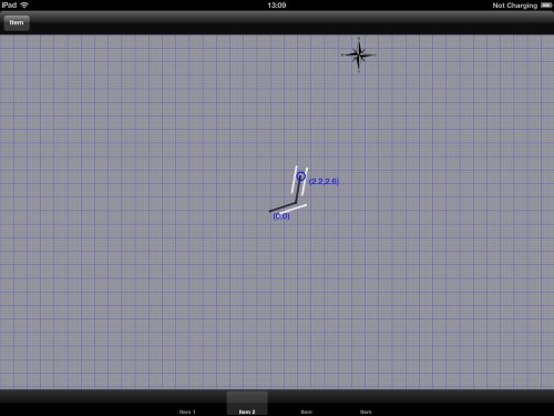
This is the world map view, where black line is robot movement and white line is reading from sensors. Units shown are meters. I have managed to position it in 2mm error in straight line using implemented PID for distance control.
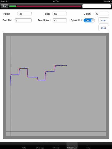
PID demand and actual speed. I will resend this pict with different color for demand and actual, but for now this one shows the progress. As for the noise on speed, i have no idea where does it come from. It can either be bug in encorder reading, speed calculation or PID parameters. Work in progress... Bugfixing was done and now it works like a charm. You cant imagine how much problems can unaligned holes on encoder produce :)
P.S. i will try to update text in regards of comments from you guys...
Navigate around and map the area
- Actuators / output devices: 1:18 tamiya gearbox, 2x540 Mabuchi motors, 2xservo
- Control method: autonomous with manual mode: iOS iphone/ipad
- CPU: LPC2148 ARM7
- Operating system: my own
- Power source: 7.4V Lipoly, 2x7
- Programming language: ObjC for iOS, Keil C for ARM
- Sensors / input devices: CMPS03, 6xSharp IR, 2xSRF08, Motor encoder
- Target environment: indoor, outdoor
This is a companion discussion topic for the original entry at https://community.robotshop.com/robots/show/scater-bot
 We love video of robots here.
