

Update: 12/14/10, Frntc hppy updt
Update 11-21-10
I finally uploaded the video's I took last month. the 1st video is a trip to sporting goods store to buy a real compass. the 2nd is after buying the compass and comparing it to the bot, while traveling back to starting point. the 3rd is after making an adjustment to how the satellite radio antenna mounts.
Bottom line: the bot works great, but its original mission is in question. the bot works great in some vehicles like my chevy truck, but it hates my Mazda RX-7 - it spins wildly out of control. I've learned how sensitive compasses can be in moving vehicles.
even in my truck, when traveling in certain places, like over large metal bridges, the compass receives lots of noise, and the robot oscillates back and forth like crazy. I'm thinking about ways to "remove the noise" from the signal such as averaging the samples to smooth the spikes in the data. any other advice would be appreciated.
also on my agenda for this bot, is to add an IR Receiver and use a standard TV remote to detangle the wire from time to time. I'll do it mostly for the learning experience of how to do such a thing. eventually I'll program in an automatic detangle routine, but I figure I'll still need a manual way to do it also. I may add another LED on the top spinning deck to see it operate better at night. my girlfreind gave me a small blue 1" plastic pointing hand, so it might be neat to see that glowing blue at night as it points north.
Update: 10-07-2010
Done for now, pending more field testing.
I added the "solar panel power plant", which takes 12v from small solar panels (2x6v @ 166mA), steps it down to 8v for charging the 6v battery. a diode prevents solar panel from draining battery at night and adds more resistance which drops charging voltage to about 7v.
a week of field testing in my truck yielded a lot of data....
popsicle sticks had to be replaced with #10 bolts, now the unit is much more stable. large rubber feet are also held in place by the same bolts. and the entire units sits on dash, and really hasnt moved at all, no matter how I drive, or what bumps potholes I hit - lots of road construction in my town right now.
I can see I'm going to need a pair of buttons to manually rotate deck because if I turn him off and back on again, he wont know how tangled it was before being turned off.
had to replace my custom fuse holder with a real one. the solder joints kept failing, presumably from vehicle vibrations.
the compass module seems to get a lot of interference from the vehicle. however, I still havent calibrated it according to parallax instructions. Ive been focusing on the physical hardware. Tonight I calibrated it, so more field testing tomorrow.
next problem to solve - figure out how to make and post a video. Im probably last person on earth that hasnt done it yet.
latest pictures:
new bolts and proper fuse holder
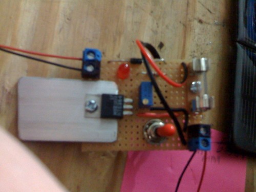
"Solar panel power plant" - scrap piece of aluminum came in handy, and really does heat up reducing 12v to 8v, at 100mA approx.
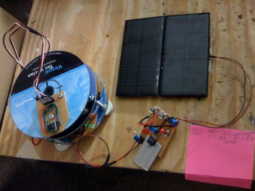
all three pieces sit on the dash nicely, and surprisingly stable because of the wieght from 5 AA batteries, and large rubber feet.
09-25-2010
This is my first robot. I think it counts as a robot, yes?
I wanted to make a robot that had a reasonable purpose, although I'm probably stretching it :-) .
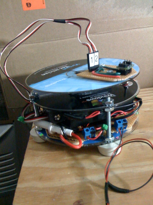
I have a XM satellite radio in my truck, and the provided little antenna can be mounted on the roof, but I decided to keep it on the dash board, and its my perception that here in Massachusettes, if I'm driving north or east the reception is spotty, so this idea came to me when trying to figure out what my first robot should be. (its really just an excuse to make my first robot). the main body is nothing more than 3 cd's, and some popsicle sticks.
I've seen other people use cd's here so that was part of the design inspiration. they are stong, thin, lightweight, etc. it uses a parallax basic stamp2, the hm55b compass module, and a continuous rotation servo. its almost done. I first built it on their development board and it worked mostly so I decided to build it in final form. although popsicle sticks may not be robust enough for a moving vehicle.
I will velcro the satellite antenna to the upper deck. because the upper cd deck will be spinning and it holds the compass module and the wired antenna, I avoid tangling the wires by not allowing it to spin more than 360 deg in either direction. if it gets to that point, it reverses the direction 330 degrees.
not sure how long the 6v battery pack will last - i suppose it depends on how much work the servo has to do. I'm guessing 3 or 4 hours. as soon as I'm done with phase 1, and because I know a few things about solar panels, I am immediately planning phase 2 - attaching 2 little solar panels (5" x 2.5" each) to sit next to it to always charge the batteries. 2 x 6v panels wired in series will produce 12v, and a voltage regulator will knock that down to 7v for charging the 6v battery pack, which is 5 x 1.2v nimh = 6v. and there should be enough juice coming from the solar panels to drive the robot and charge the batteries. I think all my robots will have solar panels involved somehow. theres a lot of hoping and wishing happening here.....
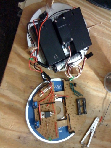
inside compass bot - 5 battery pack, and servo attached to middle deck, and circut board on bottom deck. the 2 blue terminal mounts are for the battery and the future solar panels. I also have a tiny on/off switch, 3a fuse, 5v regulator, headers for the servo, compass, and serial connector. I wish I could find a PCB mounted USB-B connector.
the perfboard circut board has since been screwed to the bottom cd - not shown above.
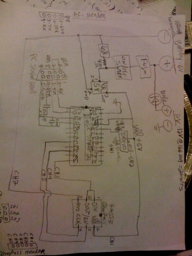
phase 2 will be the solar panel sub-board (off of this bot) for combining the solar panels, with another fuse, 7v regulator, led indicator, and a diode to prevent the solar panels from sucking juice from the battery at night.
I'll post the code after I refine it after its working.
because I'm a newb to all this, I keep making rookie mistakes, 1 after another....
**** Current Problem to Solve: I cant get my pc to talk to the chip. so I'm still debugging the connections. the pbasic editor says "no stamp found". it also says Loopback yes, Echo No. I know the bs2 chip is good because I moved it back to development board and it shows up just fine. I'm getting 5v and good ground at all the right places. all wires and signal lines have good continuity, except the DTR line on serial connector, because capacitor is inline (according to an EE friend). or is that my problem? obviously, 1 of those statements I just made may not be true even thou I checked it, rechecked, and checked it again. I'm in for a dope slap. solved
points my XM Satellite antenna southwest
- Actuators / output devices: cont.rotation servo
- Control method: autonomous
- CPU: Parallax BS2
- Operating system: pbasic
- Power source: 5x1.2v nimh
- Programming language: pbasic
- Sensors / input devices: compass
- Target environment: inside a moving vehicle
This is a companion discussion topic for the original entry at https://community.robotshop.com/robots/show/sattrack-compass-bot

