

CURRENT PROJECT WORK
(Most recent first)
August 19, 2011
More body work, cutting and filing...and thinking about where to place the boards...
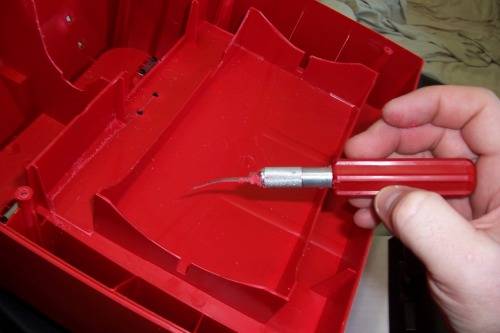
Cutting an opening with an X-ACTO saw blade so that the inside of the robot may be accessed by opening the front door. Be careful when sawing with these, the blade bends quite easily.
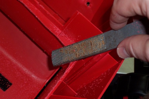
Filing the edges of the cut smooth.
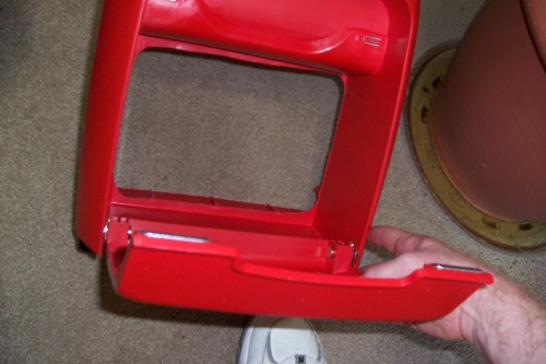
The newly cut hole behind the front door
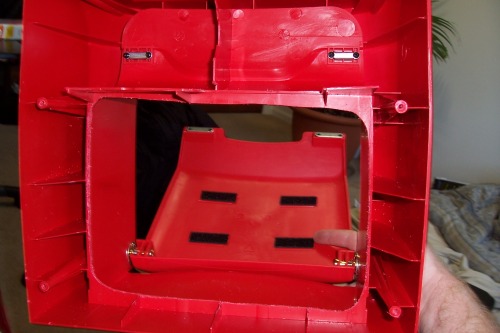
View from the inside-out
Upper area to be cut with razor saw
Piece removed after being cut with razor saw
Another angle...
With the top back on. Hey, those aren't Jawa feet!!
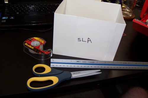
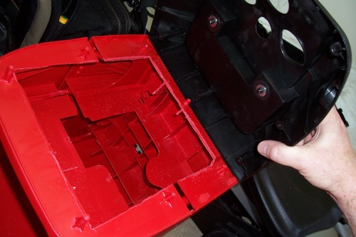
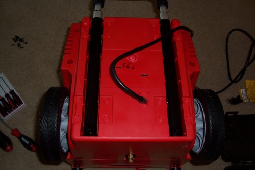
Paper model of the proposed SLA dimensions being considered to check form and fitment. The following photos show potential electronics placement to take advantage of ease-of-access provided by the existing door. Of course, a metal frame will be built to secure everything , these are just photos of me thinking aloud of some potential places to put the boards.
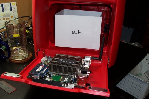
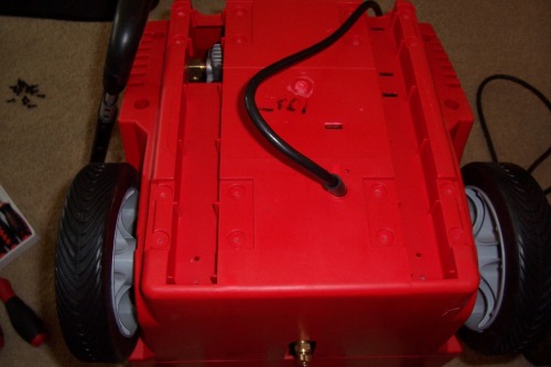
Where to put the electronics? Good design practices state that the heavy battery should be centered over the wheels, as shown. This photo shows a motherboard placement on the inside of the door, where they could be easily accessed. I borrowed this idea from a guy named Paul who made an R2-D2. If you haven't seen his website, click the link to the left and go there RIGHT NOW and take a look, it is absolutely amazing! The photos of his door are as follows:
(Courtesy Paul's R2-D2 blog)
(Courtesy Paul's R2-D2 blog)
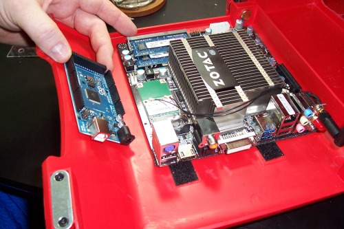
By placing the electronics on the inside of the door, all interfaces and wiring could be very easily accessed, and adjustments made without the pain of having to unscrew and remove the black curved top of the robot each time something has to be tweaked.
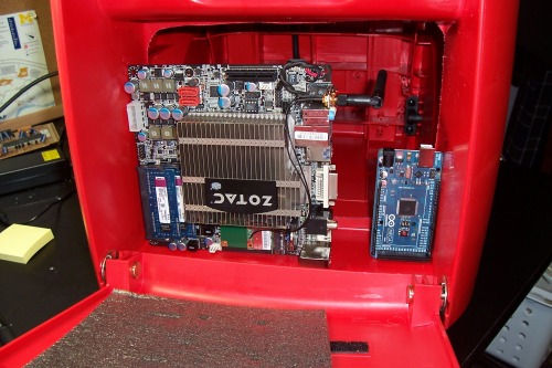
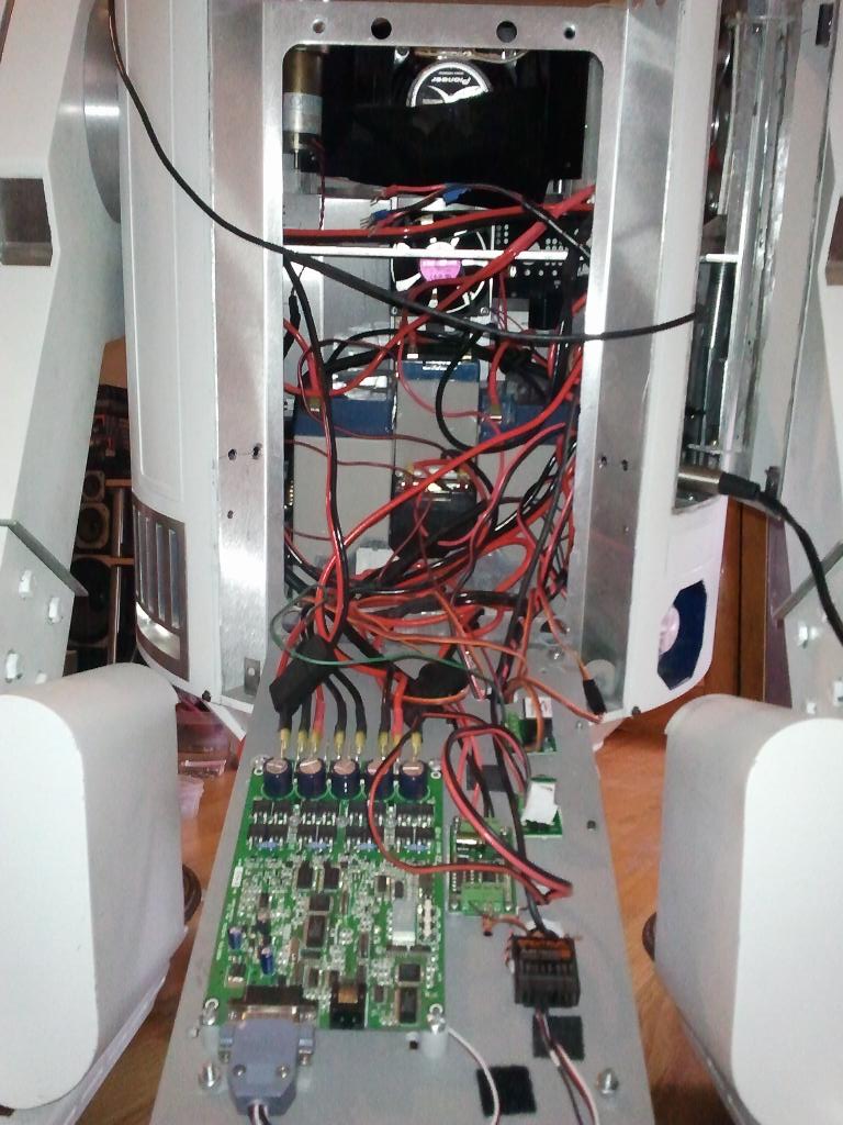
Another placement would be directly in front of the battery as shown below so that the weight of the boards would be borne by the metal frame and not the hinges on the front door. This type of placement is what the Pioneer robot uses:
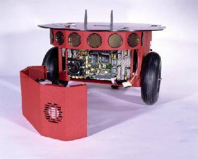
(Photo courtesy Adept MobileRobots)
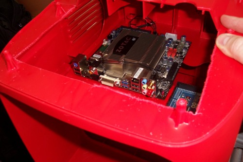
Another potential placement would be near the top which was cut out, placing them over the battery, and underneath the black curved top. A logical choice, this is at the top of the robot, any heat from the motherboard could be easily routed out through a side vent. As stated before; however, this area is not easy to access as the top would have to be unscrewed and removed, unless a hinge was used to attach the top as shown below:
Any suggestions from the LMR crew with respect to electronics placement would be appreciated! :-)
That's all for now, will be purchasing a Parallax Wheel & Encoder kit and begin building the frame in about 30 days from now.
July 6, 2011
Project work began a couple of weeks ago (7/6/2011) with the puchase of a Zotac Mini-ITX motherboard, interfaced via USB to an Arduino Mega 2560.
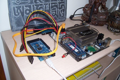
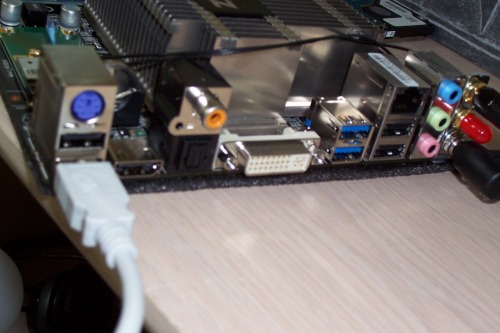
The Zotac has plenty of USB ports and other interfaces on the back, and includes two wireless antennas. Included on the board are a Dual Core Intel Atom D525 and NVidia ION GPU.
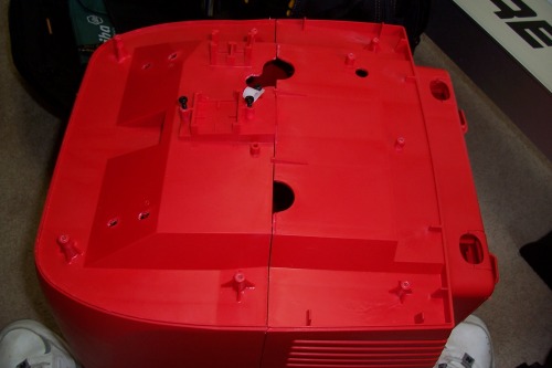
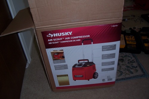
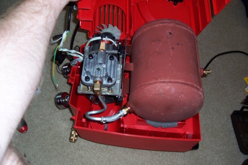
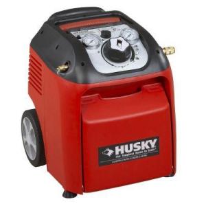
Today (7/25/2011) I purchased the Husky Air Scout air compressor from Home Depot, and began to take it apart in order to repurpose it as a robot chassis:
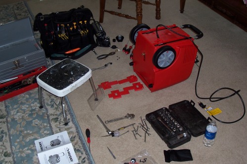
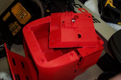
All of the screws were set into plastic, so great care must be taken when re-inserted so as not to strip the plastic. The large potentiometer knob came off very easily, and the compressor fittings on either side were removed with a crescent wrench to allow the top to be gently lifted off, exposing some compressor tubing and guages.
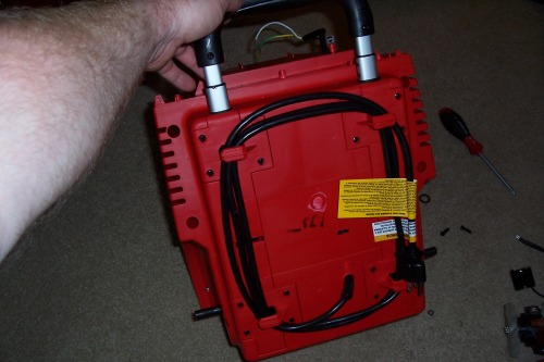
The airport-style tote handle may also be removed as shown in the photos below if you so choose, but I decided later to put it back on in case I wanted to pull the robot around instead of carry it everywhere while it is in development :-)
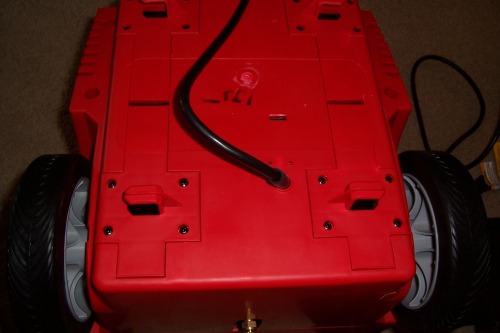
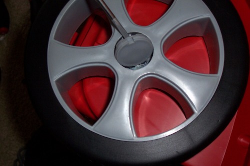
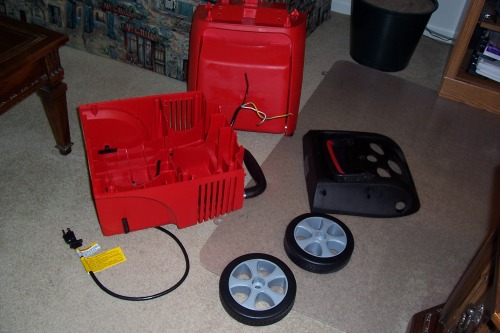
In order to open the front and rear halves of the chassis, the wheels had to be removed to expose a screw that was set inside of the wheel well as shown above, just beneath the fixed axle.
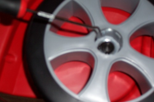
Below is a photo of the plastic hub cap being removed from the wheel with a screwdriver:
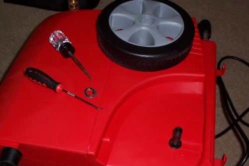
On the inside, a small horseshoe-shaped wire holds the wheel to the axle via washers. This wire was a real pain to remove, and the only way I could have done it was with a pick and awl shown in the photos below:
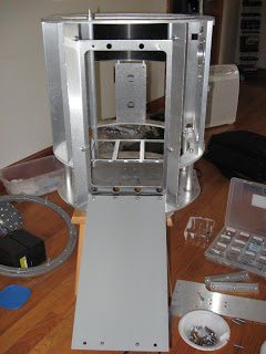
With both wheels removed, the wheel well screw was now accessible and the 6 screws holding the front and back halves together could be removed and the chassis opened:
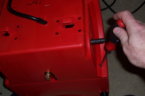
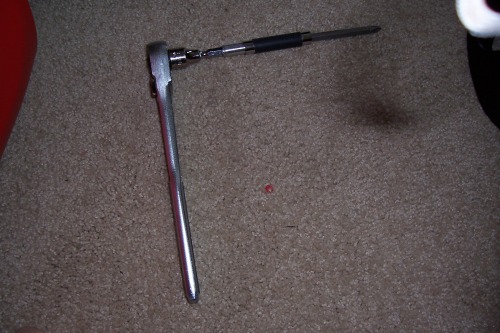
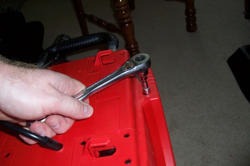
One issue was that the other 4 screws (total of 6) were so deeply recessed that I had to jerry-rig a very-long screwdriver made of a Dewalt drill bit, some extenders, and finally a socket wrench at the end:
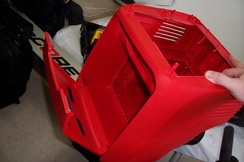
Now that all of the screws were removed, removing the back half of the chassis was a snap:
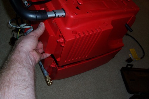
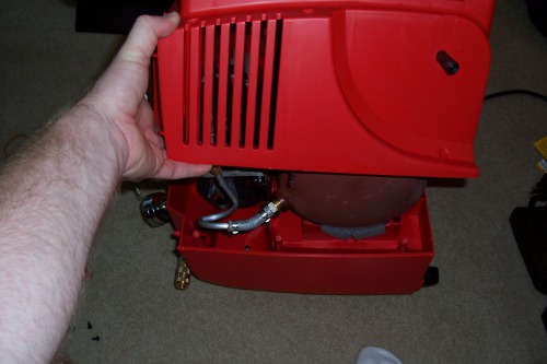
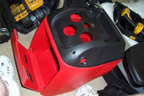
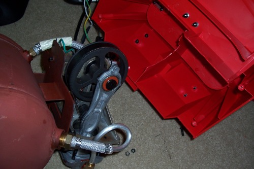
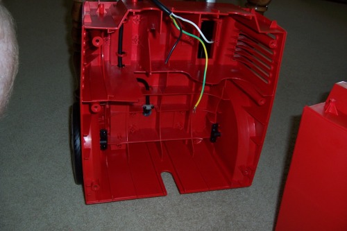
Removing the back of the chassis revealed the very large, and very heavy air tank and associated tubes and piping:
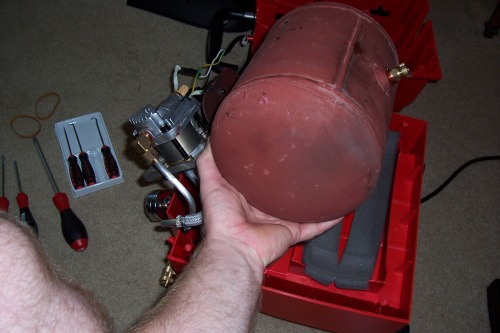
Removing all of these innards significantly reduces the weight. Out-of-the box, before disassembly, this product weighed 35 pounds. With everything removed, the chassis and wheels weighed a mere 10 lbs.
Here's a couple photos for the mechanical engineers out there showcasing the 25 lbs of compressor parts:
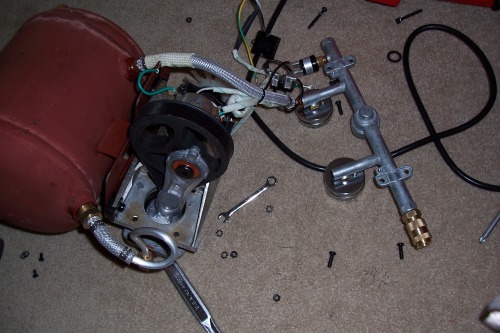
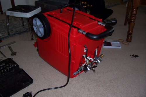
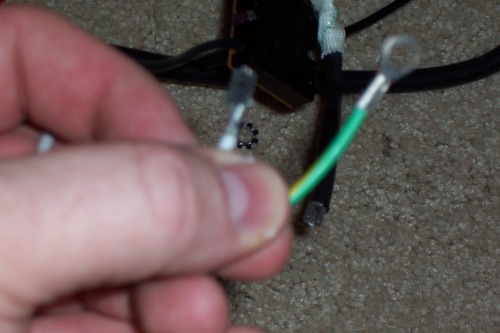
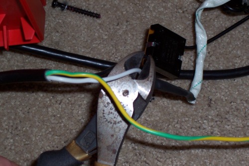
Next, some wires from the 3-prong electrical cord, which was wrapped around the back of the unit like a vacuum cleaner, had to be cut from the potentiometer that was from the knob on the top of the unit. The other 2 wires had terminal ends. As shown below. I elected to keep the electrical cord intact on the back of the unit in case later I want to charge the robot by including a DC charger inside the robot and using the existing electrical cord by simply plugging it into the wall.
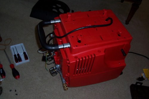
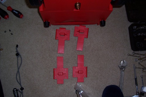
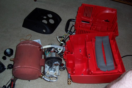
Shown below are the final photos of the separated halves of the chassis.
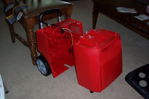
That's all for now. Next steps include purchasing a couple of motors, a motor controller, Sealed Lead Acid batteries, and a caster wheel. Then I will try to reverse-engineer a metal frame/skeleton inside the chassis to hold these components and the electronics so that no additional stress is placed on the plastic, which may fracture and break.
INTRODUCTION AND PROJECT RATIONALE
This is the beginning of my first robot project, Robot Unit 01
The robot will be built inside of the chassis of a Home Depot Husky Air Scout (Air Compressor). A photo of the gutted air compressor sans air tank and hardware is shown above. The photo below is the compressor as purchased from Home Depot for $99.
This robot will be a service robot, built to help and assist people, and Asimov's Three Laws of Robotics will appear as comments at the top of the source file which contains main() :-)
- A robot may not injure a human being or, through inaction, allow a human being to come to harm.
- A robot must obey any orders given to it by human beings, except where such orders would conflict with the First Law.
- A robot must protect its own existence as long as such protection does not conflict with the First or Second Law.
I hope that this project documentation will help others who wish to build their own robot with the Husky Air Scout chassis, I think for $99, this is a pretty nice contoured body for a small home robot. Who knows, maybe we can start a community of modders around this platform!
Specifications for the final version of the completed robot:
Hardware
- Chassis: Husky Air Scout Air Compressor (Cheap $99 Home Depot air compressor gutted and used for robot body)
- 1.8GHz ZOTAC Mini-ITX motherboard
- 4GB DDR3 RAM
- Seagate Momentus XT ST95005620AS 500GB 7200 RPM 32MB Cache 2.5" SATA 3.0Gb/s with NCQ Solid State Hybrid Drive -Bare Drive
- Arduino ATMega2560 microcontroller
- Microsoft Kinect Sensor
- 12v sealed lead-acid batteries
- 12v motors & encoders, motor control board
- Possibly a CrustCrawler AX12+ robotic arm
Software
- Ubuntu 10.10
- ROS (Robot Operating System) Open source software from Willow Garage
- OpenCV
- Point Cloud Library
- Programming Languages: C, C++, Java, Python
- Development Tools: Eclipse CDT IDE for C/C++
Project Rationale
The recent release of the Turtlebot and Bilibot platforms for use with ROS (Robot Operating System) present an excellent opportunity for hobbyists to learn about ROS on a low-cost development platform. The Turtlebot and Bilibot both retail for approximately $1200, and incorporate an iRobot Create, Microsoft Kinect, Intel Atom processor, and frame structures upon which hobbyists may mount their own components.
I began to take a careful look at these two platforms in order to determine for myself which would be the most extensible for future enhancements, from both a hardware and software perspective. In addition, I wanted to create a robot that had 'personality', keeping in mind that several of my favorite TV and movie robots had something that the Turtlebot and Bilibot were lacking - a contoured robot body or chassis which enclosed the twisted mess of wire and framing. Something more than just a box with wheels.
In my opinion, Whitebox Robotics has the market cornered from an aesthetics standpoint with the 914, which is essentially a PC on wheels encased in super cool body paneling. Unfortunately, the 914 has a price tag of about $5000, making it far out of reach for the average robot hobbyist. Look at the pictures...which would you rather have running around your house?
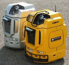
Fig 2. From left to right, Whitebox Robotics 914, Willow Garage Turtlebot, Garratt Gallagher's Bilibot
So, although the Turtlebot and Bilibot are a nice turn-key solution for beginning enthusiasts like myself who have yet to learn the finer points of electrical and mechanical engineering, they lacked a certain personality due to the absence of a clearly-defined outer shell. So off I went to Home Depot, after reading Gordon McComb's Robot Builder's Bonanza, to scout out materials to begin the construction of a custom robot which would use ROS and the Kinect. I spent some time looking at metal angle brackets, aluminum sheet metal, hardware, plywood, attempting in my mind to try and figure out how I was going to make a metal box with wheels look personable. In order to use a sheet metal design, I would likely need a metal brake, and several other metal-working tools whose expense was beginning to add up. Always in the back of my mind was the question of how I was going to apply a 'skin' to the robot to give it shape and form. That would be tricky. Aluminum? Wood? Vacuformed plastic? This was getting very tricky and would likely be quite expensive when all was said and done.
Fig 3. C3PO....with and without skin
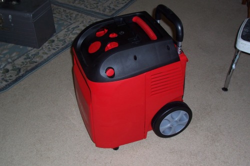
So after walking around Home depot looking at all kinds of materials and PVC pipes, I stumbled upon the Husky Air Scout compressor. I stopped for a moment and thought to myself, "you know, that would be a cool little robot". I took a closer look at it.
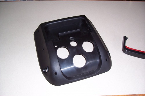
Fig 4. Flip-down front access door
It had a relatively durable plastic construction, already had 2 wheels to which I could add a front caster, weighed 35 lbs with the compressor, and would be very light without. The front had a hinged flip-down access panel (shown above) which revealed the air hose, the back of the compartment could be cut out to reveal the entire inner chassis where batteries, electronics, and other components could be mounted. Side air vents and a small fan already existed on the side. The knobs and control panel on the top could be removed and would provide a platform for a future robotic arm. In my mind, things were beginning to take shape.
Husky Air Scout compressor with zoom photo at HomeDepot.com:
http://www.homedepot.com/h_d1/N-5yc1v/R-100645228/h_d2/ProductDisplay?storeId=10051&keyword=huack+air+scout&jspStoreDir=hdus&Nu=P_PARENT_ID&selectedCatgry=SEARCH+ALL&navFlow=3&catalogId=10053&langId=-1&ddkey=Search
Hope you enjoyed this introduction.
More to follow, stay tuned. Many thanks to fritsl and GroG for their kind words of encouragement when I first blogged about this project proposal, and also to OddBot who helped me with some motor and controller questions. And thanks to the entire LMR community, for giving me the courage to build this, my first robot.
- Jawa
P.S. A quick note about the air compressor parts as many have asked...yes, the compressor is still completely operational and will housed inside of a wooden box (instead of the plastic which I used for my robot). No compressors were harmed in the making of this robot, it's still alive! :-)
Service Robot
- Actuators / output devices: Parallax Wheel & Encoder Kit
- Control method: 2GHZ 802.11g wireless
- CPU: Dual Core Intel Atom 525 1.8 GHz Mini-ITX
- Operating system: Ubuntu 10.10
- Power source: 12v Sealed Lead-Acid Batteries
- Programming language: C++, Java, C
- Target environment: indoor
This is a companion discussion topic for the original entry at https://community.robotshop.com/robots/show/robot-unit-01
