

TURAG ( http://www.turag.de )
The TURAG (TU Dresden Robotik AG) was founded in 2003 and consists of 20 students. Most of them are studying Electrical Engineering, Mechatronics or Information Systems Engineering. The goal of the group is to give students the opportunity to test their theoretical knowledge in practice. To make that possible the group participates regularly in robotic contests. Since 2006 it participates in the eurobot contest every year. Their sixth participation in this contest was in 2011.
Eurobot (http://www.eurobot.org)
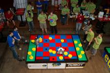
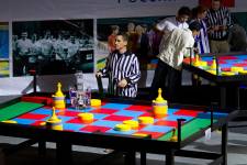
The Eurobot is a yearly holded international contest for autonmous robots. The main task is nearly the same every year. The robots of two teams play on a 2m x 3m field. Within 90seconds the robots have to solve a task as fast and as well as possible. They must do that absolutely autonomous. The team that makes more points within the given time wins the game.
Every country in the world may send three teams to the international competition. If more than three teams of one country want to participate in the Eurobot Competition, a national contest needs to be hold. The two best and one chosen team may participate in the international contest.
Task – Eurobot 2011 (rules: http://www.turag.de/files/downloads/EB2011_rules.pdf )
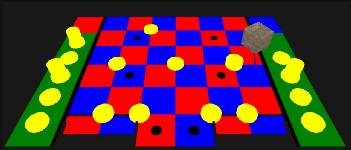
| Playing Field |

The theme of the Eurobot 2011 was „Chess'up!“. The robots had to play a game combined out of chess and draughts on a 2m x 3m field. The main part of the field was checked in the team colors – red and blue. The robots had to place the playing elements – pawns, queens and kings; diameter: 200mm – exactly on the field colored in their own teamcolor. The goal was to place as many playing elements as possible on these fields. One possibility to get more points was piling the playing elements.
To make the game more interesting and exciting it was absolutely desired to take elements from the opponents fields.
Development
When in September 2010 the Eurobot 2011 rules were released we started developing the robot as fast as possible. Some questions that we had to discuss in the first stage of development were:
-
How can the robot find the playing elements on the field?
-
How can the robot handle one or piled playing elements?
-
How can the robot pile playing elements?
-
How can the robot find playing elements lying in the range of actor/sucker/arm?
-
Do the robot need a storage? And what kind of storage could we use?
-
What kind of drive is the best?
-
What's the perfect robot size?
All these questions were discussed a long time. Many possible solutions were found and dismissed.
You can see that all these questions are sensor concept and construction questions. We didn't talk about software and electronics in this first stage of development.
(You can find the answered questions under the point construction.)
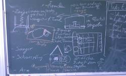 |  |
| Notes of the main concept meeting | First test |
Finding the raw concept was a real group work. All members of the group discussed together. When we chose a raw hardware concept the software and electronics development began.
During the Eurobot Contest 2010 (one year before) we had some organisational and some time problems. To avoid the occuring of these problems, we made a strict time line, talked every week about the actual status of work and implemented backupsystems whereever it was possible und usefull. If someone was not able to get ready in time, someone else had to help.
One of the best project planning ideas was to participate in the Czech Eurobot Competion 2011. That event was held nearly one month befor the German Competition. On the one hand it was a deadline for the completition of the robot and on the other hand a first test under real competition terms. In the years before we have never had a complete robot system when we started to travel to the national competition. The robot was not absolutely ready when we arrived Prague, but we have.
Construction
To describe the construction i will answer the question placed some points before. You can find some more information on the poster of Scrat: http://www.turag.de/files/downloads/EB2011_Poster.jpg
-
How can the robot find the playing elements on the field?
Camera? Laser range finder? Other sensors?
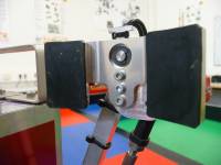
We used a HOKUYO laser range finder. The reason is that laser range finders are very robust sensors in relation to light, surface color and surface reflexion. An other reason is that measured values are very easy to interpret in comparison to cameras or other sensors.Moreover we use this sensor since the Eurobot 2008. For this reason we were able to use nearly the same interpreter software as in the years before.
In addition we implemented two distance sensors. The reason is that these sensors are much more precise as the laser range finder, but the range of the distance sensors we used (0,45m) is much smaller than the range of the laser range finder (4m). We decided to use these sensors in close-up range to increase the positioning accuracy. Only with this increased accuracy it was possible to determine the element positions that precise that the robot was able to take them with its actuators.
-
How can the robot handle one or piled playing elements?
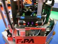
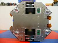
We decided that pushing elements is the easiest way to manipulate them. Because of this decision the robots base plate got its characteristic form (see picture "top view" below). In addition we decided to mount some suckers on the frontside and on the backside. The reason was that we wanted to fix the playing elements on the robot. With this solution it was possible to move faster without losing the elements.
-
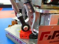
How can the robot pile playing elements?
Gripper on a linear axis? Two-joint-arm with a sucker on a linear axis, like we used two years before? Other concept?
We decided to use an absolutely different concept to pile the playing elements. Two arms with parallel leaded gripper parts – one arm for the left and one for the right side of the playing elements. Together they were able to keep and lift the elements. Every arm got two servo motors. One to lift the arm and one to open/close the gripper side.
-
How can the robot find playing elements lying in the range of actor/sucker/arm?
Camera? Distance sensors? Color sensor? Diffuse reflection light scanners?
We decided to use diffuse reflection light scanners with background suppression on every part of the robot were it was necessary to know if something is present (playing element/part of the field/opponent). We implemented very small sensors without teachable switching range. The used sensors are available with switching ranges of 15mm, 30mm and 50mm. Instead of these selected sensors it was no problem to change one, if its' switching range is not perfect.
-
Does the robot need a storage? And what kind of storage could we use?
There was no limitation of playing elements that the robot may handle at one time. But it was written in the rules, that many actions are prefered by the organizers. The reason is that it is more interesting for the audience if the robots do many actions. There were two main points why we didn't implement a storage:
- We were fearful the robot collects many playing elements and is not able to find a good unloading position within the last X seconds of the game. In this case we had many elements but less points.
- We wanted to find and take the opponents elements. That's only possible if the robot is able to drive fast and precise on the field without pushing already placed elements from their position. That's easier if the robot diameter is as small as possible. The reason is that planning the path over the field is not really easy. But it's easier to find a way through the placed elements and the opponent if the own robot is small.
-
What's the perfect robot size?
Like described one question before: it is easier to find a way over the field if the robot is very small. But what is the perfect size? We thought that it was great if the robot could drive over the field without moving the own already placed elements. That implied a defied robot size that we decided to use.
-
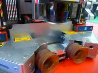
What kind of drive is the best?
Omnidirectional? Ackerman? Differential? Other?
We dicided to use a differential drive. The reason is that this kind of drive is easy to control, fast and easy to build. In addition it is possible to use odometers. Odometers are an easy way to determine the robots position on the field. The principle is easy: You have to build two free rotating very thin wheels with encoders on the drive axis of the robot. If these wheels are rotating the encoder creates a signal and it's possible to calculate the robots position. We decided to pull these wheels to the ground with a spring. Because of this construction they will never lose contact to the ground. One year before we used an omnidirectional drive and had many problems with the positioning of the robot.
Pictures of the CAD Model
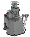 | 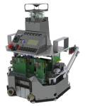 | 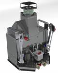 |  |
| CAD Pic 1 | CAD Pic 2 | CAD Pic 3 | CAD Pic 4 |
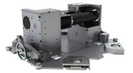 |  |
| CAD Pic - drive | CAD Pic - arms |
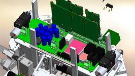 | 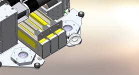 |
| CAD Pic - electronics | CAD Pic - accumulators |
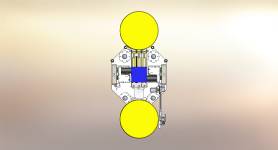 |
| CAD Pic - top view |
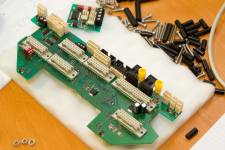
Electronics
In 2008 one of our members wrote a project work about reusable and free combinable electronic components. He layouted a control unit and some other boards. Until today we use this system, because it's easy to use, it works very well and it is possible to customize the combination of boards to your needs.
Within the last years we optimized and extended this system. Only the power supply board and the board where the electronics can be placed (called backplane) need to be layouted new every year, because it has to fit the needs to the actual task/electronics.
This year we used three of this combinable control electronics systems:
-
drive control: system control board + position detection board + motor controller board
-
system control: system control board + i/o board
-
laser range finder: system control board
In addition we have a display with an own controller. In the whole system work 6 ARM7 – ATMEL - AT91SAM7* controllers and 8 ATMEL ATMEGA controllers. (If you compare the numbers of the controllers with the system architecture overview you will detect a difference. Both „CMU-CAM3“ and „Mausometrie“ modules were never integrated. In addition some Components are missing in the overview.)
I think it's not necessary to describe the whole electronics. You can see nearly everything in the system architecture overview. http://www.turag.de/files/downloads/EB2011_Systemarchitektur.pdf (I'm sorry, it's in german, but it is nearly without any german word. ;) Please ask me if you have any questions.)
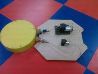
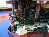
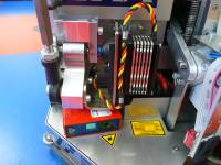
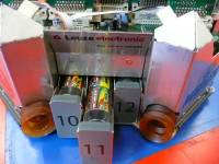
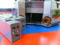
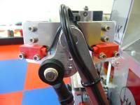
Assembling and harnessing
 | 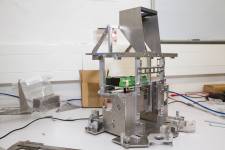 |  |
| Assembling 1 | Assembling 2 | Assembling 3 |
 |  |  |  |
| Assembling 4 | Assembling 5 | Assembling 6 | Assembling 7 |
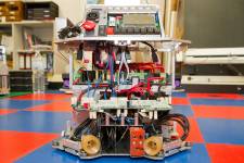
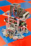
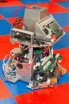
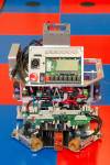
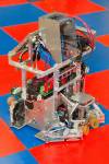
Robot "Scrat"
 | 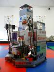 | 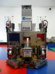 |
| Scrat 1 | Scrat 2 | Scrat 3 |
 |  |  |
| Scrat 4 | Scrat 5 | Scrat 6 |
 |  |  |
| Scrat 7 | Scrat 8 | Scrat 9 |
 |  |  |
| Scrat 10 | Scrat 11 | Scrat 12 |
 |  |  |
| Scrat 13 | Scrat 14 | Scrat 15 |
Positioning Concept
I think the positioning system is the most important system on the most robots. A robot that does not know where it is, is in most cases not able to solve its task. Often collisions or loss of functions are the consequences.
It is a horrible feeling to see that a robot, that made a lot of work, is not able to solve the given task just because it does not know where it is. Our group had this problem in the Eurobot competition 2010.
Because of this experience we decided to use odometry as the main positioning system. We already used that system in robots that we built for the Eurobot Competition from 2007 to 2009. We made good experiences with it. The construction and functionality of odometry was already described in the paragraph „construction“.
Odometry is not perfect. The position error increases with the driven way and depends on various other parameters. We correct this error with two color sensors. These sensors are mounted on the ground of the robot and detect the color transitions on the field. Depending on these values it is possible to calculated the actual robots' position.
It was planned to use two more position detection systems but the colorsensors and the software worked very good. We didn't need the other systems. One of these Systems should detect the drift of the odometry wheels in axial direction. We wanted to use special mouse sensors to detect that drift. The other system was our Opponent Detection System that is not only able to calculate the opponents' position. It is also able to localize our own robot.
The Opponent Detection System consists out of 5 beacons, 3 on the edges of the field, one on the top of the opponent and one on our own robot. It is possible to measure the distances between the own or the opponents robot to the three field beacons every 40ms. The three distances are measured by detecting the difference of the time of fligt between ultrasonic and radio.
Software
- Game Control
The Game Control is the software unit that decides what the robot has to do. The next action is chosen depending on the actual game situation. This year we used a tactics and robot simulation the first time. It was really helpful during the concept studie phase. We were able to see where an additional sensor was required and could choose the best tactics without robot hardware.
We used Player and Gazebo for that simulation because these tools are for free. In addition they are the most widespread simulation tools.
All of the games tasks could be pooled into two main tasks:
-
take an element from its actual position
-
bring an element to a specified position
There were only two questions needed to answered:
-
Which element has the robot to take?
-
Where has the robot to bring the element?
To make it possible to answer these question in the best way various weighting factors where implemented:
-
How long is the way to an element?
-
Where is the opponent?
-
Is the element lying on our or the opponents field? Or is it lying ouside of a valid area?
-
Is the element lying on a bonus field?
-
What's the actual playtime?
-
Is a free field close to an element? Is a free fiel close to a border next to an element.
-
How hight is a tower?
Every action starts depending on theses weight factors. All of these factors are chosen with the purpose to make more points as the opponent. ;)
 |
| Gazebo, Player, Stage simulation |
- Internal Mechanics
The internal mechanics is a software module that coordinates complicated motion sequences depending on sensor signals. It controls the arms, the vacuum pumps and the valves – not the drive. Since the Eurobot competition in 2008 we use visualSTATE for these complex state mashines.
- Motion Control
The software module Motion Control controls the two motors of the differential drive. It receives motion instructions (target poses) from the Game Control. Depending on the actual position, the motion instruction, the dynamic and static limitations of the robot it calculates the pwm frequency for every motor. It uses a cascaded PID controller with feed-forward control.
One interesting limitation of the robot is that it is not able to follow complicated splines. The hardware was able to do that but nobody wrote the software that makes the robot able to do that. It can only move along a straight line OR rotate. It is not hard to write the software that allows the robot to follow compicated splines, but it is harder to make this software robust and the robots' movements faster than movements that consist out of straight lines and rotations.
- Path Planning
The eurobot playing field is around 2m x 3m big. While a game the position of the opponents robot and the positions of many playing elements can change. In addition there are some solid parts on the field. The robot may not collide with the opponent, the playing field and the playing elements that are already placed on scoring fields. For this reason the robot has to plan the way from point A to point B over the playing field.
The A* algorithm is used to calculate the shortest and safest way over the playing field. Some adjustments were done that the algorithm is suitable to use with our differential drive system. The algorithm considers the mechanical limitations of the robot and calculates a way also out of complicated situations.
- Position Detection
The construction of the positioning sytem was already described above. A odometry system detects the driven way. The failure of this system is corrected by two color sensors that detect the fields' color transisions.
A Kalman filter is used to calculate the actual robots position determined by the sensor signals. For the reason that the motion control is not able to handle position jumps, an additional filter that compensates these jumps was integrated. The game control module does not need this filter and uses the most actual position all the time.
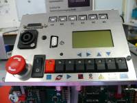
- HMI
The HMI is the interface between user and robot. Various menus allow the user to detect problems, move actuators and to start the robot.
- Laserscanner
The Laserscanner software module receives the measured distances from the HOKUYO laser range finder. Depending on these values it detects the positions of the playing elements on the field.
Competition
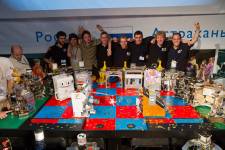
- Czech Eurobot Competition in Prague
This year we decided to take part in the Czech Eurobot Competition in Prague. The competition was nearly one month before the German Eurobot Competition where the three best german teams were determined. The Czech competition was the perfect place to test the robot under real conditions. Furthermore the competition was our deadline. The robot needed to be alsmost done to this competition.
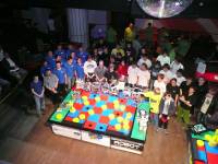
When we arrived the competition place „Retro Music Hall“ in Prague we were really surprised. The competition place was a club. It was great. During the competition robot „Scrat“ was instead of electronic problems and a lot of software bugs able to get the third place out of 11 robots.
 |  |
| Prague 1 | Prague 2 |
 |  |
| Prague 3 | Prague 4 |
- German Eurobot Competition in Ludwigshafen
When we came back to Dresden after the Czech Competition we had nearly three weeks to go. We used this time to fix some bugs, optimize the motion control and implement some new software features. Because of the experiences from Prague some sensors were displaced and three additional sensors were installed.
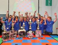
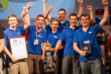
The competiton in Ludwigshafen was great. It was organized very well. Ten teams played for the title "Deutscher Meister" and the participation in the international Eurobot competition in Astrachan/Russia. The three best teams got the permission to represent Germany in Astrachan. After a lot of exciting games our robot Scrat reached the final rounds. Three exciting games later our robot Scrat was "Deutscher Meister" and our group was permitted to represent Germany in the international Eurobot compettion in Astrakhan.
 |
| Ludigshafen |
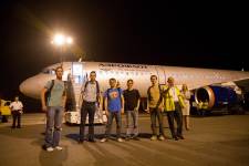
- International Eurobot Competition in Astrachan/Russia
When we arrived Astrachan/Russia we were really excited because only the best 50 teams from all over the world got the opportunity to come to Astrachan. A lot of interesting games, nice people and gret impression waited for us.
The additional software improvements that we made between the german competition and the final competition provided great results. After the five qualifying rounds we were at the first place without one defeat. We arrived the semi final of the final rounds without big problems. But our semi final opponent made us some. He implemented the right strategy, one of our sensors made a measurement error and because of this reasons and some bad luck we lost the semi final. The game for place three was really exciting. Scrat won it and made the third place of all eurobot robots.
 |  |  |
| Astrachan 1 | Astrachan 2 | Astrachan 3 |
 | 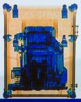 |  |
| Astrachan 4 | X-Ray Scrat | Astrachan 6 |
If you have any questions about the robot or one of its' parts do not hesitate to ask. :)
Within 90seconds it tries to put more playing elements on its own areas on the playing field than the opponent.
- Actuators / output devices: 5 servos, 2 60W motors, 4 vacuum pumps, 4 vacuum valves
- Control method: completely autonomous
- CPU: 6 x AT91SAM7* 48MHz, 8 x ATmega (most of them are ATmega 88 and ATmega 168)
- Operating system: eCos on 5 of the AT91SAM7*, no operating system on the ATmega controllers
- Power source: 1 x 7.2 V 4500 mAh = electronic supply, 2 x 7.2 V = 14.4V 4500 mAh = power supply
- Programming language: Assembler, C
- Sensors / input devices: 7 distance switches, 3 Color Sensors, 1 laser range finder, 2 wheel encoders, 2 motor encoders, + some more, 2 distance sensors
- Target environment: indoor flat surfaces, field size: 2.1 x 3m
This is a companion discussion topic for the original entry at https://community.robotshop.com/robots/show/robot-scrat-turag-eurobot-2011
