

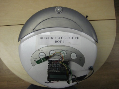
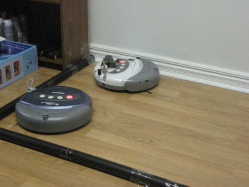
This project consists in displaying the ability for robots to work together in order to perform a certain task. This is one of the first projects I worked on at RobotShop. We chose to use the iRobot Roomba platforms for this project to show that robots can work together collectively in order to clean a room effeciently and in less time.
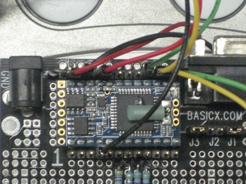
The Roomba has it’s own microcontroller and intelligence with it's sensors and actuators. Since we wanted the robots to “talk” together we needed a second level of intelligence. We therefore used a Basicx microcontroller that we connected to the Roomba. This microcontroller module enabled us to add hardware to the robots in order for them to work together and recognize each other during their task.
We mounted the BX-24 microcontroller on the Roomba platform and powered the BX-24 using the existing port found on the iRobot Roomba. We therefore determined which pins were needed in order to be able to connect them correctly to the BX-24.
Following are the connections on the Roomba:

We then powered the BX-24 using the connections above. In order to correctly power the BX-24 we needed to regulate the power coming from the Roomba battery. We did this using a 5V power regulator which we connected to the pin 1 of the Roomba port. We then connected this 5V power to the BX-24 power input and connected the ground to the pin 7 of the Roomba port.
We also connected the transmit and receive pins of the Roomba port to a desired port on the BX-24.
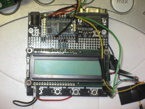
We wrote test programs to see if the BX-24 could communicate with the Roomba. We were able send commands to the robot example: clean and we were able to receive sensor information from the Roomba.
We then showed information that we received from the Roomba, on the LCD screen that we placed on the BX-24 development board.
We wanted the robots to communicate with the PC using a Bluetooth serial communication using the Sparkfun bluesmirf Bluetooth module in order for the robots to entirely cover a floor surface. The robots needed to understand that another robot had already covered a certain area. A communication protocol therefore needed to be implemented in order for the robots to perform their tasks efficiently.
See table below for connections:
Name |
Pin Roomba port |
Pin BX-24 |
Power |
1 |
VCC |
Ground |
3 |
Ground |
TX |
4 |
Com1 pin2 |
RX |
7 |
Com1 pin1 |
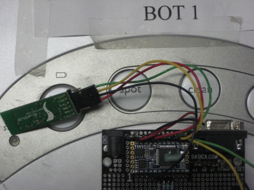
We connected the Sparkfun Bluesmirf module to a port on the BX-24 but, ran into a few issues with the communication and we were not receiving the right information from the Roomba, in the BX-24.
We therefore decided to move on to the tracing of the Roombas in an environment without using the BX-24. We knew that we were able to connect with the Rootooth Bluetooth device on the Roomba using C# and we decided to try connecting the robot through Matlab for the tracing via bluetooth. The PC intelligence was programmed in MATLAB since it has proved to be efficient to trace paths in this programming language. We were then able to connect the Roomba with the Rootooth and Matlab to trace in a virtual environment and could see its coverage.
Since this project consists in robots working together collectively we tried connected a second robot using a second Rootooth. We could connect up to 8 devices on the same Bluetooth dongle but, the concept was proven with 2 robots. We created a second Bluetooth com port and assigned it to the second robots Rootooth. We modified our code in order to be able to connect two robots at the same time and have them clean and trace their coverage in a different color.
Calculations
In order to be able to trace the correct information coming from the Roomba encoders, calculations for distance and angle need to be made.
The Roomba gives us the distance traveled in millimeters since the last distance which was requested. This information is given in the form of 2 bytes, signed. We therefore, needed to verify if the information we got from the robot was positive or negative and display the information correctly. This information is not enough in order to adequately trace the robots travel. We also need the angle of the robot during this travel.
The robot gives us information on angle in the form of 2 bytes, signed which is the angle that the robot has turned since the last requested angle. In order to determine the angle we therefore needed to calculate the distance traveled by the robots two wheels which is the left wheel distance minus the left wheel distance.
In order to find the angle in radians, we used the following formula:
Angle in radians = (2 x difference)/258
258 is the distance between the Roombas wheels in millimeters. The calculation therefore needed to be done every time distance information was polled from the robot.
Calculations were also needed in order to place the robots orientation in the bin. Following are the positions of the robots:
Robot 1:
X = 8.255 (radius of the Roomba)
Y = 81.995 (height of bin – radius of Roomba)
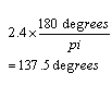
Angle in radians = 2.4
Robot 2:
X = 208.245 (length of bin – radius of Roomba)
Y = 81.995 (height of bin – radius of Roomba)
Angle in radians = 0.5
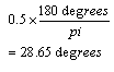
The angles found for the robots are off from what we would expect them to be (315 and 45). This was due to the fact that there is some error coming from the robots encoders. The original values were altered in order to get the best possible results from the robots and to trace the results as accurately as possible.
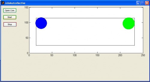
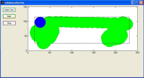
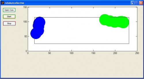
Here are print screens of our results of the Roomba mapping. As you will see, the robots will start in their respective corners until they are connected and the start button is pressed. Once the start button is pressed the robots will start a cleaning cycle and begin to trace their coverage using information received from the robots encoders.
Following is an example of the tracing with iRobot Roomba.
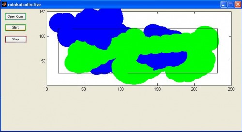
We also traced in the same bin using two iRobot Roombas at the same time:
After a while, the errors from the Roomba encoders became more prominent but, mapping was done successfully.
Example Matlab Code for Robots:
packet=[142 2]
BT_SendPacket(packet, bt_handle)
pause (0.1)
Data = fread(bt_handle, 6, 'uint8');
%Data = BT_CollectPacket(bt_handle)
disp(Data)
Read_Data = isempty(Data);
if Read_Data == 1
packet=[135]
BT_SendPacket(packet, bt_handle)
packet=[142 2]
BT_SendPacket(packet, bt_handle)
pause (0.2)
Data = fread(bt_handle, 6, 'uint8');
disp(Data)
else
remote_control=Data(1);
buttons=Data(2);
distance_high=Data(3);
distance_low=Data(4);
end
distance2=0;
for i=1:8
bit1=bitget(distance_low,i);
bit2=bitget(distance_high,i);
distance2=bitset(distance2,i,bit1);
distance2=bitset(distance2,i+8,bit2);
end
if distance2 > 32767
distance_final=(distance2-65536)/10;
else
distance_final=distance2/10;
end
distance_total=distance_total+distance_final;
diff_high=Data(5);
diff_low=Data(6);
diff2=0;
for i=1:8
bit1=bitget(diff_low,i);
bit2=bitget(diff_high,i);
diff2=bitset(diff2,i,bit1);
diff2=bitset(diff2,i+8,bit2);
end
if diff2 > 32767
diff_final=(diff2-65536);
angle_degrees=(360*diff_final)/(258*pi);
angle_radian=(2*diff_final)/(258);
%angle_string=num2str(angle_radian);
%set(handles.angle_last,'String', angle_string);
else
diff_final=diff2;
angle_degrees=(360*diff_final)/(258*pi);
angle_radian=(2*diff_final)/(258);
%angle_string=num2str(angle_radian);
%set(handles.angle_last,'String', angle_string);
end
%plot virtual world
angle_tampon=angle_tampon+angle_radian;
%angle_tampon_string=num2str(angle_tampon);
%set(handles.angle_total,'String', angle_tampon_string);
[x(1),y(1)] = pol2cart(angle_tampon,distance_final);
y(2)=y(2)+y(1);
x(2)=x(2)+x(1);
x(1)
y(1)
% axes(handles.Virtual_Layout);
%axis([0 223.5 0 89])
axis([0 250 0 150])
rectangle('Position', [15 25 216.5 90])
plot(x(2),y(2),'o','MarkerEdgeColor','b','MarkerFaceColor','b','MarkerSize', 45);
This project consists in displaying the ability for robots to work together in order to perform a certain task.
This is a companion discussion topic for the original entry at https://community.robotshop.com/robots/show/robokut-collective