Review: Lynxmotion SSC-32U USB Servo Controller

This is my writeup following my selection to review the Lynxmotion SSC-32U USB Servo controller.

 Let me first apologise for the length of time it has taken me to get this writeup started - I have been inundated with many things; work, personal and gigging with bands. I am now hoping to get caught up as best as I can!

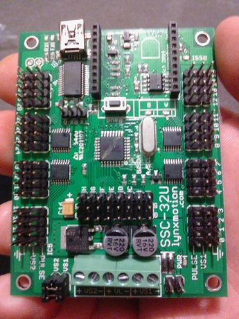
The Lynxmotion SSC-32U is a fantastic board, making the controlling of multiple servos very simple, with easy-to-administer commands giving the user full control via a serial connection.

In addition to the 32 servo pins there's also a bank of 8 input pins, for connecting various sensors to the board.

This servo controller can be used for a variety of projects where multiple servos need controlling with ease, or from a microcontroller that does not have the necessary pins or grunt to do so on it;s own.

When I submitted my request to review this board I was going to incorporate it into a project plan I had for a desktop assistant to control some pan/tils servos and also read some ping sensors and the likes.

In the time I have been pondering this review I have slightly changed my attempted project; I aim to put together some small robot arms, and use this board to control their positions. these arms will assist in the holding, turning and positioning of perfboards and circuit boards, or the positiong/holding into place of wires, to assist with things suchlike soldering. a Python program running on my PC (eventually a built-in Raspberry Pi Zero) will pass commands to the board, allowing quick and easy rotation and movement at the click of a button.

Still a desktop assistant innit :)

Unboxing


Unboxing was a very straightforward process - the board came sealed in a plastic bag, along with a Mini USB cable and a small instruction manual. It is a very minimal packaging, but it doesn't need anything more; you only need to a power source and the servos themselves and you're ready to go.

The manual is very basic, but scharrette kindly sent me a lnk to the full online guide so it's all gravy baybee!

Using it - TO FOLLOW

This board is easy as peas to get running thanks to the in depth online manual. (http://www.lynxmotion.com/images/data/lynxmotion_ssc-32u_usb_user_guide.pdf#page=24-26)

The guide is well worth a flick through, as there are so many options regarding setup that could be used. The design is very flexible - especially with power options. You can power the whole board from one supply, split supplies when using servos of different voltage requirements, or even 3 supplies when wanting to keep the logic board powered seperately.

As shown in the manual there are several options for communicating with this board (there's an XBee socket onboard), but the main one I wil be using for now is via USB.

Controlling the servos is as simple as using the folllowing commandcomprised of the following data:

● : pin / channel to which the servo is connected (0 to 31) in decimal

● : desired pulse width (normally 500 to 2500) in microseconds

● : servo movement speed in microseconds per second*

● : time in microseconds to travel from the current position to the desired position. This affects all servos (65535 max) *

● : carriage return (ASCII 13)** 


This structued string of information allows simple, yet detailed control of each servo.

I am hoping to write some functions which will handle banks of servos by sending this command for each servo channel used.

This should enable making a robotic arm-based project simple.


Controlling a Servo - TO FOLLOW

Using this board to control a servo is unbelievably easy! I shall shoot a quick video to show how easy it is.

I have been using this board with my raspberry pi via the USB connection; I have found it very beneficial to create a set of python functions to make is simple to send the required command information to the controller. I will finish it up and make it pretty then I will stick it up on here for people to use.

Controlling a group of Servos - TO FOLLOW

As with the individual servo control, controlling groups of servos is just as simple; the controller board is extremely responsive, allowing for several commands to be processed in quick succession.

I have written a simple python class to demonstrate both singular and group control - a video will follow soon.

Desktop Assistant - TO FOLLOW

In order to fully show what this board can do I have been thinking of project ideas that can use a multitude or servos.

The obvious choice would be a Hexapod or similar walker. I would love to create one of these, but with poor fabrication skills and little/no access to laser cutters and 3D printers I don't feel I could do it justice.

This got me thinking... Maybe I could come up with a tool to assist me in fabrication, like a smart helping hand. Something to hold components in place while I solder them, and can rotate/manipulate the parts at the touch of a button. With the right application it could even be voice activated!

For now I'm thinking of a small wieghted base, with 3 robotic arms; two on the outside, one at the top, and finally a motor in the middle. This middle motor can be used to control a turntable, for rotating PCBs or parts that I am shaping.

The top arm could be used to hold PCBs, and rotate them on command - ideal for double sided soldering jobs!

The side arms could be used to hold wires or components that need soldering, and hold things in place, leaving my hands free to wield the soldering iron and solder.

This will allow me to get everything in position and concentrate on a good solder joint rather than wishing for ten arms!

And adition could be some potentiometers attached to the servos - this could allow for feedback of position, and open up the possibility of teaching the arms movements.

:-)


Update - having been let down on an order of robotic arm kits I am looking for advice to move this review-come-project on.

I have plenty of micro servos, but I am looking for some laser cuttable or 3D printable arm kits. I should have my 3d printer up and running once I source a control board.

As soon as I can get those I can finish this!


Thanks for your patience!!


PS - I've started collecting chopsticks to make some really basic arms to demonstrate my code for this fantastic controller!

It works really well wI think other controllers and SBCs. Recently I have been using mine with my Raspberry Pi. The Pi runs a simple Python webserver, and upon button presses on the Web page sends serial commands to the SSC-32U.

This combination would work great for a Hexapod; the SSC-32U handling movement while the Pi handles processing (maybe even from a Pi Cam, integrating OpenCV for image processing ! )

1 Like

re: SSC-32U

I use this board for my Ava robot, to control 8 arm servos, 2 neck, 2 ears, all 7.4 volt.  I am generally happy for noticed a few issues.  

The board assumes on startup that it has to move to some default (center) positions, as fast as possible.  The doc acts likes this is a good thing, but in my opinion it is not.  It is dangerous and can burn out servos very quickly.  I think it would be better if movement to some kind of initial position was user controlled at a user speed.  In my case, I need to control the shape of the movement of arms to the initial position (around obnstacles) and I can’t.

The other related issue I encountered is with supplying enough current to the servos on startup.  Because they all try to “jerk” to the initial position, they all draw a lot of current all at once, which overloads the 7V 4.5Amp switching regulator I was using, running off a 14.4V 4S Lipo, causing the board to go a bit crazy and jiggle all the servos and not do the right movement…  I think this reg would have been enough if it weren’t for this startup “jerk” behavior.  I was forced to redesign my power supply to have a separate  7.4V battery for the servos, this fixed it.  Maybe I am ignorant on something, but I think it should have worked the old way.

Other than these issues (which burned out a couple of expensive shoulder servos, everything else has been good.  I ran 6 hours a day for 2 days controlling 12 serovs with the board at SXSW.

There are many ways to control that initial jerkiness.

One method is to include both a powerup and a power down process in your logic to position the servos to a fixed point then power down the board, logically. Meaning the uProcessor controls the power to the SSC32U instead of a manual process. Have both the startup and the shutdown processes position to the same servo locations. Then, once they are all positioned for system shutdown, issue an SSC op to change the servo ports to digital IOs and set the pins to LOW. The servos will be cut off.

At power up, the uProcessor issues an SSC op to configure the servo ports as digital IOs and again sets the pins to LOW, again, no position commands will be responded to by the servos. Then, after a few seconds, (the onboard caps in the power rails will be charged by then) begin a process that starts to reconfigure each individual servo to the startup position. Dont use a Group Command, issue them one by one, so that the current draw is ramped up slowly as each servo returns to the same preset state the shutdown told it to. This is because the servo horn may have been moved while off power and is not in the physical position anymore that the shutdown placed it at. So it is just informing the SSC32U board where the servo horn should be at, and if it did move while off power, it will be put back at that position at this time. Then, because the ops are being issued one by one, the pins are being reconfigured back from being digital IOs and into Servo PWM pins and each servo is coming online individually, instead of all at once, taxing both the current draw at the power source and the SSC caps that are present to level that sort of thing out.

Once the startup process is completed for all the servos onboard, issue a Group Command to place them all at their initial positions that you are using currently for full startup. To cut down on some time, some servos can be op’d to initialize in unison, such as the ears for example, instead of them being individual ops, they can be back to back or even a two group servo move at the same time, but issued individually from all the rest.

The point being the SSC pins are digital LOWs at startup and shutdown and bring the servos up individually to avoid that mass current draw that occurs when everything receives its initial power and overtaxing the current.

Something else to examine in the way of power is to add up all of the MAX current draw values from everything and ensure the power source being used can handle that PEAK Current.

A Third thing would be to add the optional 3rd Cap to the SSC32U. There is a feature on the board that permits this, by way of the two header pin connections up near the USB port connector. There are no pins installed as shipped but a header can be soldered in and a third cap mounted as either onboard or wired via the header to a third external cap. A third cap will assist in the peak current draws also both at startup and while active by the way of one more “reserve” that current can be drawn from during peak current requests. It is not always necessary to implement the 3rd cap feature but it is present for that purpose. And as stated earlier, ensure there is an adequate time slice at powerup in order to give all the caps time to come up to full charge. If you are curious in how long that actually takes, use the values on the Caps to reference its datasheet online and it will give the time slice it requires to reach full charge. Then multiply by the number of caps and round up to the nearest second. Caps charge quickly in human terms so if youre not into that type of precision timing, a few seconds where your uProcessor is performing some other initialization step should do it.

It could be just the third cap could solve your issue, however, parking servos at shutdown and ensuring each is at park position at startup Individually, will also ensure they come online one by one. And by Parking servos, it is meant the servo is moved to some position, then that servo pin is converted to a Digital pin from PWM, and set to LOW. There will no longer be a PWM signal to the servo but the horn should remain in place most of the time, unless an external force moves it thereafter. Then at startup, the servo pins are defaulted to Digital IOs and again at LOW, so that no PWM signal is seen at the servo to move it, until it is ready to be moved logically.

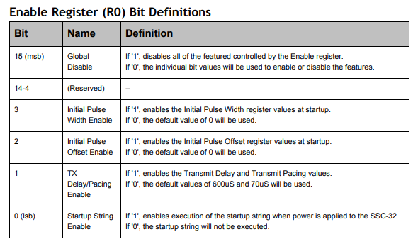
Using the SSC32U Startup Registers, one can configure all the PWM pins be Digital IO and LOW when the Atmel first receives its power. Since these are stored in onboard eeprom, an external uProcessor may not even need to issue it, but as a safe guard, use both. The registers so the pins are LOW at Atmel power up and again when a uProcessor first starts to communicate with the controller. You want to ensure the pins are all LOW before power starts to be applied to the servo power rails VS1 and VS2.

It is for similar reasons that VL should always be powered separately. and not tied to the VS rails. So that VL comes online first, configures the controller, then the VS rails brought up so they do not present any unwanted activity at the servos themselves.

Hope this all helps!

Does this help? Page 37 shows a few other possible settings as well:

image

@cbenson,

Here at Acigan, the toggling of the Register Enable bits is an in house no-no.
Reason being the eeprom life cycle.

So it is better to configure the ports as digitial IOs once in the eeprom and then issue the servo move command when ready. By that time the Atmel has imported the registers into core from eeprom and working on them in core, not at the eeprom. It saves the eeprom life.

Just being mindful of eeprom and how they die out over time when under uProcessor control. In house rule here is to write config and forget at the eeprom unless the config requires change. It should not be used as a pseudo disk drive and be toggled on or off interactively. That fries the memory address space for that particular bit setting and those also within the byte around it. Since the byte is fried, not just a single bit. So poor usage of the eeprom will damage more then just one register bit if coded incorrectly.

This is also touched on briefly in all of the versions of the SSC manuals with a sentence or two.

Its is just better to think of eeproms as write once ( ~100000 times) and read many (unlimited).

Acigan International

Also, the topic of the eeprom chips was a discussion that was with RobotShop, off forum awhile back. The older controller allowed for a user installed eeprom via a socket. An eeprom could be user replaced if it became unreliable due to life cycle burnout. The SSC32U lacks this DIP socket and using the embedded eeprom. So the entire Atmel would need to be swapped out and reflashed instead of a cheaper eeprom DIP. A process that a user lacking experience with surface mounted component replacement could not easily do. Surface mount has its benefits, but on site user replacement of a DIP chip into a socket, is not one of them.

Our In house rule regarding initialization is that it is stored on a SD/TF card in a simple txt file that a uProcesser then accesses at startup. The records are then issued to the SSC32U as a step of platform initialization. The SSC Registers are only set to Digital LOWs in eeprom at the controller. so that all ports are OFF. The uProcessor then brings them online as needed. Since the file is a simple txt one on a SD/TF, it can be edited on a PC if needed, making coding changes in that area minor. The init process at the uProcessor is just reading a txt file and sending each record to the SSC32U and then ends. The code is just a read until EOF loop. This gives the ability for extensive initializations to any of the 32 servos or any of the other ports or components on the controller since the init txt file can contain more records then necessary for bring the controller online.

What is being mimic’d in that process is how mainframes or PCs use configuration process or INI files for initialization purposes. The OS being developed in house is mimicking all that but at the microprocessor level.

For anyone reading this thread and curious of the OS being used —
It is called the Autonomous Interface Unit Operating System (AIU or AIUos). Awhile back Acigan Development recorded the migration of one of the version levels of it when it was migrating on one of the test prototypes. The MPU was removed from the platform and placed into the test breadboard, the current OS was recorded impromptu as functional, just prior to the newer release being applied to the Unit. That was awhile ago, but the recording is on YouTube so it can be reviewed even when not in the Development Lab.

The current Version and Release of the prototype currently is Revision B, Version 1.0. and the video is before that B.0.8 or B.0.9 or around there. The link text on YouTube indicates the exact migration.

There is also an audio only recording in the actual AIUnit Prototype demoing her OS and describing in detail how she functions. This is the actual prototype talking via onboard vocal and recorded. All words and phrases are stored locally on the platform with the demo being one of them. It saves Development from doing demos repeatedly to clients interested in the AIUos.

For anyone interested in what AIU brings to microcontrollers, the demo can be found on YouTube by searching “Acigan International” and viewing the impromptu recording there. For the full audio demo, there is a link to it in the description under the video.

The video does not show an SSC32U in action due to it being coded by Development at the time and required minor revision to logic to change from the original SSC32 to the newer SSC32U controller. But the platform is being prepared logically at the time of the recording for locomotion the same as the prior two prototypes (A and B) supported, Under Revision A versions of AIUos.

Prototypes today run Revision B of AIUos and are the C-Level Prototypes. Each level introduces additional functionality to the entire platform. The platforms are required to fully test and pass the in house QA upon the Operating System and are not the actual focus of the Project. The OS is. But a test bed is needed to do that, so they are fabricated also.

YouTube search “Acigan International” for the video of an ESP32 WRover running AIUos
AIUos also currently runs on an STM32 uProcessor.
Click the link under the video to hear the full audio of Prototype C.1 Charr Unum giving her own demo.