Thank evrebody 
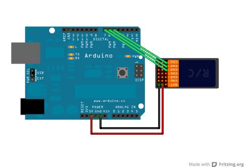
I just found a tutorial of a guy who explain how to do that https://www.sparkfun.com/tutorials/348 but in the tutorial the final code seems to be to easy and i wonder if it include the communication with the L298N and if the speed of the motor can vary.
"The Arduino would be more or less extraneous in this setup and in a sense be going to waste."
I wanna use an arduino for this project for three reason :
- Because i want to learn more aboute arduino
- Because i don’t wan’t to buy RC cc controller ( I’m 15 so ive only some pocket money ^^ )
- Because i would put a anti shock sensor or some another cool stuff who need arduino
Here is the final code of the tutorial :
/

 RC PulseIn Joystick Servo Control

 By: Nick Poole

 SparkFun Electronics

 Date: 5

 License: CC-BY SA 3.0 - Creative commons share-alike 3.0

 use this code however you’d like, just keep this license and

 attribute. Let me know if you make hugely, awesome, great changes.

 /
int ch1; // Here’s where we’ll keep our channel values

int ch2;

int ch3;
int move; // Forward/Back speed

int turn; // Turning Factor
int pwm_a = 3;  //PWM control for motor outputs

int pwm_b = 11;  //PWM control for motor outputs

int dir_a = 12;  //direction control for motor outputs

int dir_b = 13;  //direction control for motor outputs
void setup() {
pinMode(5, INPUT); // Set our input pins as such

pinMode(6, INPUT);

pinMode(7, INPUT);
Serial.begin(9600); // Pour a bowl of Serial (for debugging)
  pinMode(pwm_a, OUTPUT);  //Set control pins to be outputs

  pinMode(pwm_b, OUTPUT);

  pinMode(dir_a, OUTPUT);

  pinMode(dir_b, OUTPUT);
  analogWrite(pwm_a, 0);

  analogWrite(pwm_b, 0);

}
void loop() {


  ch1 = pulseIn(4, HIGH, 25000); // Read the pulse width of

  ch2 = pulseIn(5, HIGH, 25000); // each channel

  ch3 = pulseIn(6, HIGH, 25000);

  /*

  if(ch1>1000){Serial.println(“Left Switch: Engaged”);}

  if(ch1<1000){Serial.println(“Left Switch: Disengaged”);}
Serial.print(“Right Stick X:”);

Serial.println(map(ch3, 1000,2000,-500,500));
Serial.print(“Right Stick Y:”);

Serial.println(map(ch2, 1000,2000,-500,500));
Serial.println();
delay(100);
clearAndHome();

*/
move = map(ch2, 1000,2000, -500, 500); //center over zero

move = constrain(move, -255, 255); //only pass values whose absolutes are

                                   //valid pwm values
/What we’re doing here is determining whether we want to move

forward or backward/

if(move>0){digitalWrite(dir_a, 1);digitalWrite(dir_b, 1);};

if(move<0){digitalWrite(dir_a, 0);digitalWrite(dir_b, 0); move=abs(move);};
/Here we’re determining whether a left or a right turn is being

executed/

turn = map(ch1,1000,2000,-500,500);

turn = constrain(turn, -255, 255);
/This is where we do some mixing, by subtracting our “turn”

variable from the appropriate motor’s speed we can execute

a turn in either direction/

if(turn>0){analogWrite(pwm_b, move-turn); analogWrite(pwm_a, move);};

if(turn<0){turn=abs(turn); analogWrite(pwm_a, move-turn); analogWrite(pwm_b, move);};
Serial.print(“move:”); //Serial debugging stuff

Serial.println(move);
Serial.print(“turn:”); //Serial debugging stuff

Serial.println(turn);
Serial.print(“move-turn:”); //Serial debugging stuff

Serial.println(move-turn);
Serial.println(); //Serial debugging stuff

Serial.println();

Serial.println();
}
Thanks again 


