

just a quick update on my mini R2D2 project.

I am making some progress, but slowly, very slowly. There a just so many choices to make that sometimes I can go for weeks just thinking up solutions for all the bits and pieces of this robot without actually building anything. Thats why I started trying a few ideas to get R2D2 moving.
The plan is to get one foot working well and then copying that for the other foot. If the prototype foot is too messy, because of all the experimenting, I'll make 2 copies.
The feet are to be encased in nice triangular boxes or shoes anyway, so I can make the inside ugly and full of tryouts because that will be invisible when they're done.
Each foot will have two inline wheels. Because the leg will be tilting forward when the robot is in moving position, most weight will (hopefully) be in the front, so the motor will drive the front wheel.
The back wheel will be running free and will probably be driving the encoders. Most robots (I think) have encoders attached directly to the motor or to a wheel that is driven by the motor. When the drive wheel is lifted off the ground or is slipping, the bot will think it is moving while in fact it is not. I am hoping to prevent that by encoding the second "non-drive" wheel.
The motors I intend to use are small metal gear motors from solarbotics with, what they call, beefy tires. The broad rubber tires are good for stability. I have gotten the motor up to about 5 maybe 6 rounds per seconds unloaded running at 10V. I am guessing I can keep that up to 3 rounds per second (=30cm/s) when they carry the full weight of the robot. We will have to see.
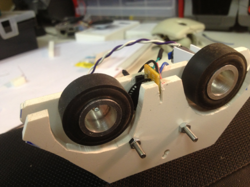
In the back of the picture you see a bit of the motor sticking out the side. The gears will be protected from dust and such with a plastic sheet using PVC foil. That stuff is quite sturdy and will protect the gears well enough.
After some clumsy experiments with white stripes on the wheels, I am now trying encoders I ripped out of an optical ball mouse. To make sure they dont go too fast, the encoderwheel is pressed against the tire. Normally in a ball mouse the shaft of the encoder wheel pressed against the ball, making it go much faster. As I don't need millimeter precision, this will give me a better chance that the processor will keep up.
In the picture you can see a bit of circuit-board from a mouse sticking out. I may have to cover that up with a piece of plastic or the encoder wheel has to move up somewhat. Or maybe I can cut a bit off the board. I allready have both photo-transistors showing pulses between 0.8 and 2.5V on the meter, but no testing on input pins of a processor has been done yet.
Next step is to attach a small circuit board on the side next to the motor to deal with all the connections for the foot. It will have connections for 9-12V for the motor, 5V or 3.3V, GND and both signals for the L9110 single half-bridge that will be mounted on the board. The two signal wires from the encoders will lead to the board and there must be room for one or two other sensors.
I want all the electronics on the foot to have short wires to the little board and then lead one UTP cable from the foot up the leg into the body of R2D2. The 12V may go up the leg using a separate cable with GND twisted around it for shielding.
As the intended brain is a raspberry, I will have to decide wheter I can get this to run at 3V.