

Yes, 6V 4amp is fine. Can you tell me where you found this power supply? Maybe a part number? How much??
Thanks!
Yes, 6V 4amp is fine. Can you tell me where you found this power supply? Maybe a part number? How much??
Thanks!
Oh that is just an example, but I just got myself a Switching Mode Universal Regulated Power Supply, Model SMP-2A by VANSON. It has 6 Output Selection: 3/5/6/9/12 V DC 2.5 Amp & 13.8 V DC 2.2 Amp.
However, i still have problems operating the arm using this new adapter in 6V. My problems begin with Step 2 of the RIOS Manual.
After i clicked the “TEST” tab when setting all servos to 1.5ms, my arm did not move according to the setups shown.
Next is when i try the SSC 32 Configurations. I can only move the base servo.
Can anyone advise me what has gone wrong here?
PS: my servo connections are according to the manual.
Thanks dude! I understood the concept le. haha
Before you test your arm, go to the ssc-32 button, and make sure all servos are checked across the top. Move all the sliders so that your robot is in a “home” position; could be anywhere.
When done, save the configuration as “Home” by clicking on the save icon on the lower right.
Now, click on the Load Config Icon on the lower right. This makes sure that your configuration that you just created is loaded.
Now try the Test button. After it goes to all=1.5, click on the button in the lower LEFT. This should send it to the home position you programmed in your configuration.
My guess is that your servos are not checked in the configuration, therefore they are not working.
I have found through extensive use of the arm that the configuration is key. I even go to the SSC-32 button and load the Home configuration on a regular basis, just to make sure.
Try it and let me know!
Sorry for the late reply. I was preparing for my examinations for the past one month, so the testing of the arm is delayed. Anyway, I have tried the method, but it does not seemed to be working well too.
Before I test the arm, I did follow the steps you advised: Checked Servos, Save and Load Configuration - “Home”. However, only the base is reacting to the Test.
Next i went on to SSC32 to try and move the servos. But now, only the base and gripper is reacting.
In addition, I am curious about the “shoulder” tab which leads me to shoulder servo offset. I set it as -16, since I am using port 1 for the shoulder servo. I wonder if that is right.
As the arm is a major component of the project, it is still not functioning well after so long. In addition, the project deadline is drawing near. I am really desperate now. Hahaha. Please advise me further on resolving these problems again.
Thank you very much.
With Regards,
VodkaRed
Starting from the beginning, can you individually operate each servo on the arm? Did you sort out your power supply issues?
The power adapter I am using now, is a Switching Mode Universal Regulated Power Supply, Model SMP-2A by VANSON. It has 6 Output Selection: 3/5/6/9/12 V DC 2.5 Amp & 13.8 V DC 2.2 Amp. I switched it to 6V DC which will give me 2.5 Amp current rating. So far, this is the most suitable power adapter I can find in my area.
I can operate each servo using LynxTerm but it is not consistent. Sometimes I have to change ports to make a particular part move. On the other hand, when I follow the port connections table in the manual and use RIOS, i can only move the base and gripper servos.
We have already asked you to remove the VS=VL jumpers. Have you done this?
Please submit a picture so I can see the wiring of the robot.
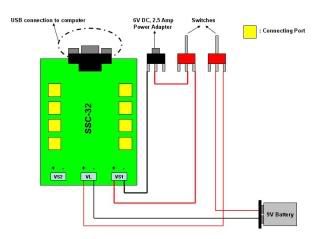
I couldn’t take a clear picture of it, so I drew my current SS2-32 wiring connection on MS PowerPoint.
i74.photobucket.com/albums/i241/ … ection.jpg
http://i74.photobucket.com/albums/i241/ryanye/ssc-32wiringconnection.jpg
Sigh… What about the JUMPER SETTINGS!
I ask you a question and you ignore it. How can you expect to resolve the problems if you can not communicate on the most basic fundamental level…
A picture would be so much better. Your drawing does not tell me very important things. Such as the wire size.
I think you are having more than one problem here. Power and communication. Are you using a serial port or a USB to serial cable. If it’s a USB cable what brand is it, and do you know if it is an FTDI or Prolific based cable?


I am so sorry for missing out such important stuff.
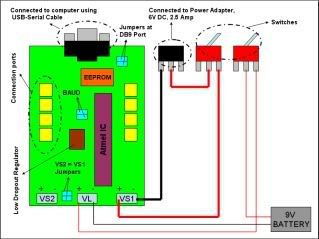
Here is the new drawing below, I hope it is clear enough to understand this time.
http://i74.photobucket.com/albums/i241/ryanye/SSC32.jpg
i74.photobucket.com/albums/i241/ryanye/SSC32.jpg
With reference to the new drawing,
I have removed the VS1=VL Jumper.
I used the smaller sized wires for for the connection of VL to 9V battery and the switch at the right. The bigger sized wires for VS1 to the Power Adapter and the left switch.
(did show on the previous drawings but the thickness of the lines turns out not clear enough. Sorry!)
I also used the USB-Serial Cable to connect the SSC32 to computer. It is a 9 pin serial port. Its brand is ATAKE, part number: A UD-AM09MY105.
I have installed the jumpers at the VS1=VS2, DB9 port, and the BAUD. Basically, the components that are on this drawing is what I have on the SSC32 now.
I sincerely apologize for any inconvenience caused. If there is anything I missed out again, please let me know. I will definitely try my best to give you the information you need. 

Ok…
Is your USB to serial cable connected to a USB 2.0 port?
I do not know if your USB to serial cable is fast enough… Can you look at the driver to see if there are any user adjustable settings. Look for:
Rx / Tx buffers. Make sure they are the same value. like 16 and 16.
If there is anything called latency please adjust it to minimum.
If these changes do not help then please try a different USB to serial cable. We highly recommend the FTDI one. It has the latency value and it works flawlessly.
You can also adjust RIOS settings for timeout illustrated on page 22. This can help speed up the communications.
Yes, my USB-Serial Cable is connected to a 2.0 USB port. I have tried adjusting the RIOS Setting for timeout, but there is still no change.
About the user adjustable setting, I have difficulty locating the driver in my computer. This is because during installation, it skipped the part of asking where I wanted the driver to be installed to. I have emailed the company for technical assistance on that. Currently waiting for their reply.
You mentioned that you do not know whether my USB-serial cable is fast enough. So how fast must it be to work flawlessly, or instead, what are the requirements for the cable?
I did look for the FTDI cable you mentioned before getting the current USB-Serial cable. However, this brand/type of cable is not commonly found in my area. Many of the vendors I asked were clueless about it. Therefore, getting a 9-pin FTDI USB-Serial cable will need to take quite some time. If you don’t mind, can you provide me with the product code or part number of the 9-pin FTDI USB-Serial cable that is most suitable for my AL5D robotic arm?
Besides the USB-Serial cable and the driver settings, what could have caused the operation problems of my robotic arm? Perhaps I can look into that while looking for the cable.
Thank you.
RIOS uses bidirectional communication constantly when it is being used. If you enable servos and they are suddenly disabled it means the bidirectional communication is failing. There is no magic number or specification for good USB to serial cables. I can only tell you some are awesome, and some suck massively. The leaders in the industry are FTDI. The one you have seams more like a cable for file sharing, so I must assume latency was never on their mind. It’s not the “speed” but the delays before high speed is allowed…
lynxmotion.com/Product.aspx? … egoryID=44
The driver is located in:
control panel
system
hardware
device manager
Ports (COM & LPT)
USB Serial Port (COM?)
Port Settings
Advanced
Because the first two pages of this thread concern power issues you apparently have not been shown the serial port troubleshooting guide. It is very informative…
lynxmotion.net/viewtopic.php?t=4702
Hope this helps!
Thanks for providing these useful information. 
Here are some information of my current USB-to-Serial Cable.
The current Port Settings are:-
Manufactured by Prolific;
115200 Bits per second;
8 Data bits;
No Parity;
1 Stop bits;
No Flow Control; and
The Receive Buffer and Transmit Buffer are already in its maximum, 14 and 16 respectively.
Based on the above settings, please correct me if I’m wrong to say that this cable is not that suitable for my applications.
The tx and rx should both be the same value… Make them both 14 or both 16. It has been reported to fix it, even though it sounds pretty silly.
If this fails to work, then I would recommend you get an FTDI cable.
The robotic arm finally works perfectly I used the 9pin to 9pin cable. Thank you for the help.
However, because my robotic arm is suppose to work in wireless. I got this CM02 and RF04 receiver and transmitter from the Singapore distributor of Lynxmotion, I was wondering how to connect the CM02 to the SSC 32. Unlike the PS Controller receiver, the power input for the CM02 is a 3 pin type.
Anyone use this model of transmitter and receiver on your robotic arm before?
If a distributor is selling a wireless device for use with one of our kits, they really need to provide you with information on how to actually use it. We can not be expected to troubleshoot this for them. 
Just guessing but it looks like it might actually be a Devantech thing (acroname.com/robotics/parts/R235-CM02-RF04.html) so maybe they will notice it here and pick up the ball.
Those information I got from my lecturer are just an introduction and description to the components. No information on how to connect them to SSC-32 circuit.
Well. I will continue to “haunt” the distributor, hopefully he can provide some technical support and assistance which he don’t usually do that. 