power problem

hello everybody,

setup:robotic hand 5 servos and 5 flex sensor made up of aluminum and resistive material and arduino duemilanove

problem:servos dont move when i bend sensors.how to provide external power supply for so many servos. i tried providing power by joining 4 1.5 volts battery and then connecting + an -ve to the battery but it does'nt work.what should i do

again same post ?

again same post ?

Did you wire a common ground with your microcontroller?

Besides the power, they have to be able to understand the signal from the processor by referencing it to ground, so you need to connect the ground side of the system power and the external power.

yes

i tried doing all the suggestions but it was not possible so i was looking for somene who could tell me in brief

Post your program please.

Do the servos “twitch” when you first connect the battery to them? And have you tested your flex sensors with a multimeter?

Copy and past your program here please, and a wiring diagram.

i dont think you need an

i dont think you need an external supply.

I built a robotic hand and it’s power is supplied by the usb cable connected to my laptop.

The code i posted should work fine with your setup.

i would also suggest to look for wrong wire setup of the servos.

i soldered around 3 boards which were not working untill i finally realised that i connected the +ve of the servo cable to a digital output. so, look for tiny errors you made. I remember getting very frustrated because it was not working. :D 

reply

yes only 3 of my servos twich when i connect it to the external power rest dont twitch . i am using 5 microservos namely hxt900 that is consuming 4.8 v. initially i connected all the +ve wires to an aluminium foil and from the foil i connected to the board.i did the same with negative terminals(i connected it to the foil in order to connect them in parallel) and connected the digital pins respectively.the sensors are working fine 1 connected it to the board and attached a single servo. 

This all sounds very strange

This all sounds very strange to me. Are you trying to connect the sensors directly to the servos??
What is the aluminum foil stuff your connecting to?


Have you tried a servo test program to check that the servos are working?

// Sweep
// by BARRAGAN <http://barraganstudio.com>
// This example code is in the public domain.


#include <Servo.h>
 
Servo myservo;  // create servo object to control a servo
                // a maximum of eight servo objects can be created
 
int pos = 0;    // variable to store the servo position
 
void setup()
{
  myservo.attach(9);  // attaches the servo on pin 9 to the servo object
}
 
 
void loop()
{
  for(pos = 0; pos < 180; pos += 1)  // goes from 0 degrees to 180 degrees
  {                                  // in steps of 1 degree
    myservo.write(pos);              // tell servo to go to position in variable ‘pos’
    delay(15);                       // waits 15ms for the servo to reach the position
  }
  for(pos = 180; pos>=1; pos-=1)     // goes from 180 degrees to 0 degrees
  {                                
    myservo.write(pos);              // tell servo to go to position in variable ‘pos’
    delay(15);                       // waits 15ms for the servo to reach the position
  }
}

Test your servos work

Test your servos work properly as per Geirs program below.

If they work fine test your flex sensors. Make sure they are connected like this…


Connect the flex sensor like this to analog 0 and use the serial port in the Arduino IDE to check their ADC measurement with this program…

void setup()
{
    Serial.begin(9600);
}

void loop()
{
    int v = analogRead(0);
    Serial.println(v);
    delay(100);
}

hello

hi phozon,

                  can i have your schematic diagram and a few photos of your wiring to the board please

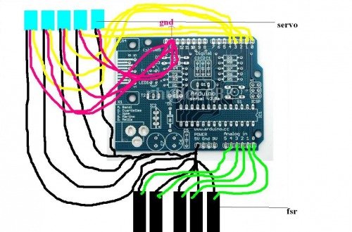
i have posted the wiring diagram

 #include <Servo.h>     


 Servo servoMotor;

 Servo servoMotor1;

 Servo servoMotor2;

 Servo servoMotor3;

 Servo servoMotor4; 


 int analogPin = 0;      // finger 1


 int analogValue = 0;   


 int servoPin = 2;


 int analogPin2 = 1;      //finger 2     


 int analogValue2 = 0;   


 int servoPin2 = 3;


 int analogPin3 = 2;      //finger 3


 int analogValue3 = 0;   


 int servoPin3 = 4;


 int analogPin4 = 3;      //finger 4


 int analogValue4 = 0;   


 int servoPin4 = 5;


 int analogPin5 = 4;     


 int analogValue5 = 0;   


 int servoPin5 = 2;


 void setup() {


   servoMotor.attach(servoPin);


   servoMotor1.attach(servoPin1);


   servoMotor2.attach(servoPin2);


   servoMotor3.attach(servoPin3);


   servoMotor4.attach(servoPin4);


  }


 void loop()


 {


   analogValue = analogRead(analogPin);                


   analogValue = map(analogValue, 0, 1023, 0, 179);    


   servoMotor.write(analogValue);                      


   delay(15); 


  analogValue2 = analogRead(analogPin2);                


   analogValue2 = map(analogValue2, 0, 1023, 0, 179);    


   servoMotor1.write(analogValue2);                      


   delay(15);      


  analogValue3 = analogRead(analogPin3);                


   analogValue3 = map(analogValue3, 0, 1023, 0, 179);    


   servoMotor2.write(analogValue3);                      


   delay(15);   


  analogValue4 = analogRead(analogPin4);                


   analogValue4 = map(analogValue4, 0, 1023, 0, 179);    


   servoMotor3.write(analogValue4);                      


   delay(15);


   analogValue5 = analogRead(analogPin5);                


   analogValue5 = map(analogValue5, 0, 1023, 0, 179);    


   servoMotor4.write(analogValue4);                      


   delay(15);

}

dats the programand wiring

schematic.jpg

Connect a high value

Connect a high value resistor from each analog pin (green wire) down to ground. Resistive sensors need to be connected in a voltage divider setup if they are to work. See my diagram below.

Program looks fine.

Looking at your schematic

Looking at your schematic you have the servo red wires going to gnd and the black wires to +5.  This is the wrong way around.  Standard convention is red is positive and black ground.  Are you sure your servos are wired OK?