Good morning ,
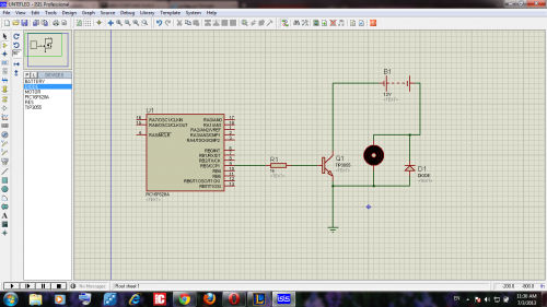
i am building a robot using an old rc car and pic and ir sensors everything works just fine until i start any of the motors
when i start the motor the pic restarts in the second and the power in the circuit becomes very low and if there was a led connected it goes so low in light so i decided to bring a bigger battery (The first was 600 ma so i bought 2500 ma battries ) but the proplem remains i putted 2 4700 C on the circuit but still just a little better the battries are fully charged i tried to connect the pic with another power source so the motor doesnt effect on it but the pic didnt start the transistor
what is the solution? thx
Add a voltage regulator to
Add a voltage regulator to power your PIC to stabilise the voltage variations caused by the current transients (the motors drawing alot of current will cause the voltage to drop).
As previously mentioned you should probably separate the motor power supply from the PIC’s supply so you’ll have the big high capacity batteries connected to your motors and the PIC powered from say a 9V battey block + regulator (7805 for example).
Don’t forget to add freewheeling diodes in reverse to the motors to prevent high voltage spikes created by induction when the motor current is shut off (1. every motor is a generator, 2. the motor coils self induction adds to the still spinning motor shaft/magnet combo inducing a voltage). The voltage spikes could destroy the batteries or power transistor.
can u draw me a schm. of how
can u draw me a schm. of how to drive a motor with another power supply? i only know how to do that with a relay
hi, thanks for your fast
hi, thanks for your fast answer
the motors idk what they are they came with the car i bought and it was 15 dollars back then so…
the stall current i measured it it was about .83 to .9 amps per motor
there isnt really a motor driver just a 2n2222 transistor driving tip 3055 transistor and i did that because using the tip with resistor with the controller didnt ive it full power
third thing i am not using picaxe i am using pic microcontroller PIC16f628a
my wires arent so thick its the internet wires but how can that affect it? they can handle about 1 A right?
i couldnt take a picture for the board my camera isnt working
and the motor doesnt work on its own power supply i tried to do that but i didnt manage do to that because i didnt know how to connect the two power supplies with the pic (driving one with another)
thanks alot 
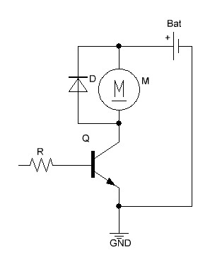
Is this close to what you have currently?
I know you didn't mention a diode, and, VCC for you is probably the 5 or 6V you are using to power the rest of your circuit.
nope i use only one
nope i use only one transistor now not two
and isnt applying 1 to Q1 will make a short circuit?
Birdmuns schematic contain
Birdmuns schematic contain disastrous flaws. Re-create yours? I dunno.
Post your own schematic. Only in this way somebody can help you.
this is the schm. of the
this is the schm. of the driver only
it works! but the proplem is that the motor runs much slower with probably lower current the if connected directly idk why
thanks for ur answer
and btw the negative of the
and btw the negative of the battery is connected to the gnd i forgot to do that
Birdmun is right
You should do it as birdmun suggested. The problem with power transistors is that they don’t have a very high current gain (beta) therefore you need a higher base current to switch your output current (collector current).
Say the max. current the motor draws is 1A and your transistor has a beta of 20 (look in the datasheet for either beta also called Hfe), then you would at least need a base current of 1A / 20 = 50mA in order to deliver enough juice to the motor. That’s way too much current than a PIC GPIO pin can handle, that’s why bird drew another switching transistor that can handle the base current with ease.
A separate power supply for the motor is easy, connect the motor voltage to one side of the motor and connect the negative part of the supply to GND of your PIC. Therefore all voltages are referenced to the same potential (common ground).
EDIT: You should use a resistor between the collector of Q1 and base of Q2 to limit the base current.
applying 1 on Q1 will make
applying 1 on Q1 will make short circuit i think am i right?
Yes a high level (1) will
Yes a high level (1) will cause Q1 to turn on which in turn shuts off Q2 and therefore stops the motor. Apply a low level (0) to Q1 to turn the motor on
but making a short circuit
but making a short circuit will damege the battery…
MarkusB, Please enlighten me.
The only thing I can think of is the lack of a resistor on the Base of Q2.
And what happens if you
And what happens if you switch Q1 on?
The suggest circuit is
The suggest circuit is nonsense because you need to limit the current flow through C/E of Q1 as well. Sure, you can use a short circuit to switch the light in your room off, but that’s not the best way. A proper solution is a Darlington circuit/transistor or a MOSFET.
Your circuit produces a
Your circuit produces a short circuit as well as soon as your micro controller tries to trigger transistor Q1. Use below circuit.
Obviously, I didn’t spend enough time thinking about it.
A resistor on the base of Q2 should(?) fix shorting issues, right? I was really only trying to get a drawing up to get an idea about what he had.
Nope, also a bias resistor
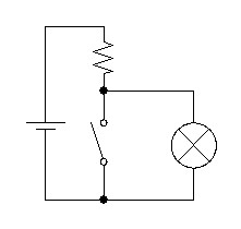
Nope, also a bias resistor on Q2 fix the shorting issue not.Think of a switch instead of the transistor Q1:
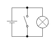
It is obvious that a bias resistor (in this case series resistor of the bulb) will not fix the problem.
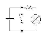
You would need to add a second resistor between +5V and the connection collector Q1/bias resistor Q2 to limit the current flow.
But then you have an inverter, no gain (in fact you're losing gain). You could remove Q1 completely. You need to connect Q1 and Q2 to a so called Darlington pair to get the current amplified.


