MmBot

MmBot (so named as she was born at Media Molecule) is designed to be a cute robot pet. The key objective is to wander around the office, interacting with people and generally making them go awwwwwwwwwwww wot a lovely robot. Internally this is gonna involve various amounts of intelligence (face recognition and stero imaging), along with a lot of smoke and mirror tricks to give apparent intelligence. Initially it's be powered by an Arduino Mega, communicating with a PC (which does the real thinking), however v2 will contain a raspberry pi.


Update (9th June)

Very quick update - I've finalyl got around to uploading to source control here: https://github.com/wibble82/mmbot

Feel free to take any code ya like and generally do what you want with it, although I take no responsibility for what you do with it etc etc bla bla.


Update (2nd June)

Just about finished hardware side of MmBot, and pondering whether to progress further or begin work on MmBot 2 in anticipation of my Raspberry Pi (which is in the post). Plus I now own a 3d printer so I can print my next robot!

More info here: 

http://robotblogging.blogspot.co.uk/2012/05/its-all-hooked-up.html


Update (26th May)

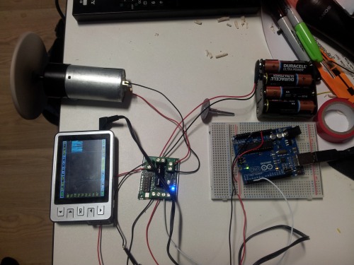
Finished my quadrature encoder and started hooking up a Sabre Tooth 2x5 motor controller, and what an amazing piece of kit! Highly recommended to anybody looking for a motor controller (if you're willing to spend a few pounds). More info here:

http://robotblogging.blogspot.co.uk/2012/05/sabre-tooth-motor-controller.html


Update (20th May)

Got to work on a proper quadrature encoder - see here: 

http://robotblogging.blogspot.co.uk/2012/05/quadrature-encoder.html


Update (10th May): Added more sensors! Decided the more the better, so I added a few more sensors to MmBot.

More here: http://robotblogging.blogspot.co.uk/2012/05/even-more-sensors.html  

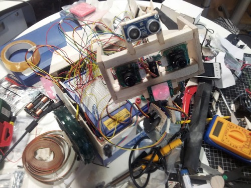
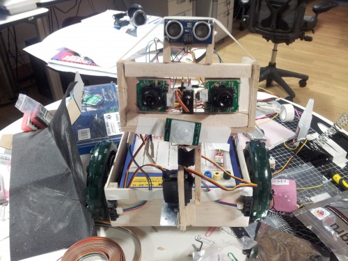
Here's MmBot with newly added ultra sound, IR range finders and a motion sensor:

Next, I started building wheel encoders using infra red reflectivity sensors and coloured disks on the inside of my wheels. This shot shows the sensor signal as the wheel turns:

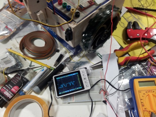
And a You Tube video if you fancy it http://www.youtube.com/watch?v=cX9qb_0jyYQ


Update (1st May)

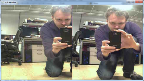
Update: Got my first stereo image feed coming from MmBot as you can see above

More here: http://robotblogging.blogspot.co.uk/2012/05/first-sight.html

And if you like debugging: http://robotblogging.blogspot.co.uk/2012/05/debugging-eyes.html


Is cute - a robot pet

  • Actuators / output devices: DC motors Stepper motor
  • CPU: Arduino Mega
  • Operating system: Windows
  • Power source: 4.5V, 18V
  • Programming language: C++, C#
  • Sensors / input devices: Camera Ultra Sound Microphone Acceleromter Compass
  • Target environment: Home and office

This is a companion discussion topic for the original entry at https://community.robotshop.com/robots/show/mmbot

Mm

Mm…Doughnuts!

Stereo imaging!

Check out new stero image feed:

eyes.png

Home made wheel encoder

Been putting together new sensors (see latest update). Quite liked this shot - it’s the sensor signal coming from my home made wheel encoder:

20120516_202904.jpg

Quadrature encoder

Began work build a quadrature encoder (with a bit of help from OddBot’s tutorial). Check out update/video above or head here for more info: http://robotblogging.blogspot.co.uk/2012/05/quadrature-encoder.html

This is it hooked up to an oscilloscope

20120518_200710.jpg

Stereo Vision

Nice. Do you have any plans with the stereo vision of the bot?

BTW, what kind of board camaras do you use?

stereo vision

Main plan with stereo vision is to use it to:

  • Build up a 3d map of the building it’s in, as it roams around
  • Identify the relative location of points of interest - i.e. if it sees a face, working out how far it needs to go to get to the person who’s face it is :slight_smile:

That should give me enough to have a robot that wanders around, picks a point of interest, goes to it, interacts, repeat…

I’m using link sprite jpeg cameras - lots of info on my experience with them here: http://robotblogging.blogspot.co.uk/2012/04/cameras-round-1.html

Unfortunately the Arduino/cameras aren’t fast enough to pull out and send over blue tooth anything close to a real time feed. I’m getting around 1 stereo image every 10 seconds - enough for my prototype. Rasperry Pi is in the post now, which I’ll wire up to 2 PS Eye cameras over usb for vision, then have it talk to an arduino for controlling everything else.

-Chris

Sabre Tooth Motor Controller

Got a Sabre Tooth 2x5 motor controller working today - awesome piece of kit! Check out the update or see here for more info:

http://robotblogging.blogspot.co.uk/2012/05/sabre-tooth-motor-controller.html

20120526_150959.jpg

Hardware complete!

MmBot is hardware complete - see update above for a bit more info, or visit here for the whole lot: http://robotblogging.blogspot.co.uk/2012/05/its-all-hooked-up.html

20120526_191937.jpg

Good to see you have progressed nicely with this bot.

You have obviously gained a fair bit of knowledge from this build.

Thx

thx :slight_smile: i’ve definitely learned from it - and this site. gonna start mmbot 2 soon though - printed out on my new 3d printer and using a raspberry pi as the brain 

Nice, what make of 3D

Nice, what make of 3D printer are you using?

Had a quick look at your robot blog, if you want to speed up the motor power correction you could try changing the snippet you posted to something like:

//Calculate how much motor_right_speed should change by
        offset = Kp*(motor_left_speed - motor_right_speed);
//Work out the new value for the right motor
        new_motor_right_speed = motor_right_speed + offset;
        motor_right_speed = max(128, min(255, new_motor_right_speed));

//Write the speed to the right motor
        MotorSerial.write(20);
        MotorSerial.write(motor_right_speed);

//and reset encoder positions (to avoid constant over compensation)
        left_encoder_pos = 0;
        right_encoder_pos = 0;

You can start with Kp = 1, and gradually increase it to make the speed correction faster. The bigger the difference between the left and right motor’s actual speed, the faster this bit of code will try to correct the right motor.

printer / encoder

I’m using a UP 3d printer by these guys : http://pp3dp.com/, although I bought it from cool components in the uk. Just getting started using OpenSCad, so will hopefully get my first bit of chassis for MmBot V2 printed tomorrow. Will post up a few of my test prints as well - did a Statue Of David I downloaded on sketchup 3d warehouse the other day which was pretty cool. Also occured to me printing out things like a scale model of an Arduino Mega might come in quite handy for working out positioning of stuff before screwing down the circuit board itself.

Good advice on the encoder - I’d definitely thought about varying the amount I change speed by based on the difference. I’m wondering if basing it off some function of the distance squared might actually be more effective - easy to try though :slight_smile:

Should also probably ‘calibrate’ the robot, so I know good estimates to start at - i.e. if left motor is turning at x, estimate a power of y to send to the motor. Just bought a couple of EMG30 gear motors which have built in 360 ticks per rev encoders, so once I’ve got them in the new chassis I should be able to get some really solid results out of the power correction.


Code on git hub

Very quick update - I’ve finalyl got around to uploading to source control here: https://github.com/wibble82/mmbot

Feel free to take any code ya like and generally do what you want with it, although I take no responsibility for what you do with it etc etc bla bla.