

@kurte Your board looks nice 
From what I understand, this board would be used in conjunction with the LSS Adapter (converting the 3.3V serial signals from the Teensy to the LSS servos), right ? If so, what would be the USB Type A used for ?
@kurte That advanced quickly! You certainly have some talent for PCB design. Some questions:
-
The LSS Adapter is made to have an MCU below it, and act as a shield; it looks like some of the parts might be too high if the LSS Adapter is above the board, especially given the short length of the male headers compared to the female headers - confirm? A work-around would be to swap the shield compatible headers for female once and use M/M headers to stack the LSS Adapter.
-
Not sure what the type A USB connector is used for?
-
Will this board be powered from the 5V pin on the LSS Adapter?
Good morning,
Just having some fun playing with a first design and seeing things that I and maybe others might like. Warning though, remember I am a retired Software Engineer who simply likes to dabble, so my electronics are probably not as good as some good EE type might design. But again it is mostly for my own fun 
Most of the time, when I am done with a version (ready to build one) I will put the designs up on a github project of mine with both the Diptrace files and zip file with gerber and drill files that I ship off to places like OshPark or Seeedstudio or PCBWay… Although with the Virus stuff not sure… That is for example where @zenta was able to grab versions of my 3.x boards.
@bdaouas - Yes it was setup to work with your LSS adapter, although I am/was thinking about throwing in the option of one or more of the LSS servo connectors on the board in case you really need the capabilities of your adapter board.
USB Type A connector - The Teensy 3.6 and T4.x support host mode USB on a second USB port. We have Teensy USB Host library, which has support for several different types of hardware, like: keyboards, joysticks, Mice, Serial Adapters and some Bluetooth support. So again for me, I may very well try to control robot using DS4 controller that is setup using simple BT dongle plugged into that port.
@cbenson - Note: The 3d rendering here is done by Diptrace using 3d STL files and the like that I have cobbled together from different locations, which may or may not be close to actual parts I might build with. Example the yellow shield connectors, could choose to install taller ones with more clearances. Pins outside of those shield connectors, could be right angle pins and again are optional. Only if you are like me and wish to have access to everything. Many of those pins would not be useful if you plug in a T4 as it only has the first 14 pins on each side. But there are some adapters which I have used that convert the bottom pins into T3.6 format, and you can use a T3.6 and at some point in the next few months you will be able to get a T4.1 (Note I don’t know the actual release time frame for these).
Power wise, so far I have it playing pretty simply and have the USB connected to +5v. so yes it would run off of the adapter power.
However if I wish to make it more independent of your shield, I might make it have simple jumper or switch to use either USB power or external power.
And if I go that route, I would probably put on my own DC/DC converter. I would not want to run the Teensy using VIN as on board converter does not like 12v… In some of the designs I have played with I have used some of them from Pololu like:
On some others I used some from Murata like:
https://www.digikey.com/product-detail/en/murata-power-solutions-inc/7805SRH-C/811-2644-ND/3438627
The Murata one I used as that was what Trossen Robotics was suing on their boards. I switched mostly to the Pololu as another member recommended them as they could handle higher voltages… Although I never have need 4S lipos…
I have also gone with cheaper voltage regulators, but you are trading off power usage and heat for price…
Thoughts?
1 Like
For the heck of it I did another version of the board above that has more stuff on it, to allow you to use it without needing the shield. Although it is still setup to be able to use one if wanted.
I have on it one of the Pololu .6amp 5v DC/DC converters, power connector 2 LSS servo connections, switch to choose which power that goes to power the Teensy. The fun of these designs is that depending on your needs, you only fill in the parts needed…
So far I have ordered any of these two, trying to decide which way I want to go
1 Like
On the LSS bus did you add a weak pull-up on-board for the Teensy RX or will you use the Teensy’s internal pull-up for it?
@bdaouas Just to confirm, what’s the pull-up used there?
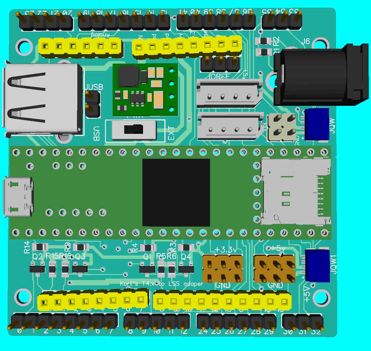
In the picture above, I am using the same circuit as the Sparkun level shifter so there is a BSS138 transistor and two 10K PU resistors connected, one on the 3.3v side one on the 5v side. In the above picture for Pin 0, that is Q2, R14 and R15, Same for pin 1 and pins 8 and 9… Wish your software serial on your adapter board was on either 7,8 (or 9, 10) to match up with T3.x/T4 hardware serial pins., but made do.
Not sure if it would show up better showing the actual current board layout:

1 Like
Note: I often end up with feature creep
One thing I am missing in the above board, that I often like in my controllers is some form of audio feedback. Often it does not need to be much, but things like, if I press a button on PS4 controller, I might want a beep to tell me that it registered. Sometimes multiple beeps to let me know I cycled through options… Like the old Botboard 2 and Botboarduino.
So I am playing around with trying to add buzzer. Normally I used a CUI 12mm size one, but don’t think it will fit here. So looking at hacking in a 9mm size one. Often times I try to add in transistor, diode, resistor. Sometimes though I just hook directly to IO pin. Will start off trying that. In above picture will try to move around the transistor/resistors for the level shifting to make it available. Probalby for T4 to pin 10 (which has some additional sound capability MQS). Maybe jumperable to what is DAC0 on T3.6…
But again feature creep.
1 Like
What about just placing 2 male headers, the transistor, diode and resistor instead? This also allows you to place the buzzer anywhere using jumper wires, such as somewhere on a robot!
I could do that (put in most everything but buzzer.
Currently I do have it hacked up to put in small buzzer as I mentioned it is using the CUI 9mm version that is setup for 3v. Could still add support hardware, but I have also gotten away with running their 12mm version by just connecting them to IO pins. And could go fancier and put in a simple mono amp, and connection for speaker, but maybe overkill for now. I suspect that when we go to RPI4, some of us will probably hook up sound to RPI4. Too many possibilities for time sink!

I might mention that my earlier board (about 11 days ago), just got back to OSHPark and shipped today. So should be here in a day or two
Not sure how long before I can pick it up and feel safe opening and not possibly worry about Cornavirus… But like many packages right now it might be a few days.
To All…!
@kurte @xan @zenta @cmackenzie
I’m going to finish and cut the proper “beta” center plates so i would like to have any input about it.
Right now it’s about the size of the Phoenix and has holes for the Pi / LSS Adapter.
Let me know so we can have this ready for you guys.
3 Likes
Sounds good.
Size of about Phoenix? Nice size, but will be interesting to see where everything will fit. That is especially when we graduate up to fully using RPI for things like ROS2 and will want some form of 3d Camera or scanner… Again not sure which sensors Robotshop will want to go with ROS support.
Again things like: IMU. I have a few different ones around here to play with including a few like the BNO080. Including one from Sparkfun with QWIIC connectors, which makes it nice to plug in?
3D camera and/or Lidar… Again can go with something simple like Lidar Lite, or a full Lidar? and/or 3d Camera?
Turtlebot 3 comes with their Lidar:
and some of them with the RPI camera. Earlier with Intel RealSense camera.
I believe that Trossen Robotics went with Intel RealSense and Orbec camera…
And if you want to go whole hog, one could go like the new UP kit coming out:
Note: I am not expecting Robotshop to ship us all of these things, but simply mentioning this as you may want to maybe think through how you might do a setup that allows for some of these sensors and potentially a suggested set.
One approach I know that Trossen did with some of theirs is to have two top plates, likewise for TB3.
Here is my current kitchen sink version of the above board:

Pretty much same as previous one, but added the transistor, resistor, diode to drive the buzzer. Also possibility of connecting an 12mm battery under the board to keep things like RTC running. … May play a little more and order set.
Not sure where I will order from (which is safer virus wise): probably OSHPark, but PCBWay has a nice price and will get them faster. But is it safe? Not sure.
EDIT: made a few more edits, like allow room for Pololu 1 amp DC/DC converter, moved SND source jumper to a place you can get to easier and changed DC power jack to a slotted version to make it easier to solder. Ordered a set of 3 from OSHPark. plus put the current files (diptrace files plus zip sent to oshpark) up on my github project
I don’t expect this plate to be anything final but would like to get a general idea of size at least.
Here is what it looks like compare to Phoenix:

2 Likes
It looks good to me! It looks like the Phoenix has more slot space for wiring, even fitting USB sized cabling through it
Looks good!
Am I correct that the dotted rounds will be the axis of the servos? So the body will be a bid wider then the phoenix but not much longer.
1 Like
Exact - The dots / circles are the servos output shaft location.
2 Likes
Here are the center plate files as they are.
If anyone want to have a look i’m open to changes of course.
SESV2-Hexapod-Center-0.1.zip (130.5 KB)
1 Like
The LSS Adapter has 10K pull-ups on the FT232 IC Rx and XBee Rx on the 5V and 3.3V side of the BSS138 mosfet
Looking good!

I hope you all are doing fine on these Covid-19 days. I’m currently working at home and they’ve just closed all schools and kindergardens…
Like @dialfonzo posted they are not that different from the Phoenix @xan (I’ve just replaced one defect servo, guess which one). I think our first goal is to make the hex work properly and have some options for different remote control systems. Then play with different designs. I do have some ideas myself, involving two extra servos and reduction gears.
@kurte a buzzer is really convenient, nice work! Your correct, I’m using FP math on the T3.6.
I’m not sure if we will ever agree on one (remote) control only. Like mentioned above there are reasons for why standard RC remotes are used for combat robots, reliability and accuracy. Then again that can be obtained through other DIY systems. The ArbotiX controller Kurt mentioned is very simple and might be good enough for many. Using high quality gimbals is a must though. Personally I really dislike the old PS2 controller when it comes to precision (data read from the gimbals). The RB-Dfr-223 sure looks like an interesting option, for some.
Personally I prefer getting data back from the robot too, like battery status and commando confirmation.


The software I’m using on this remote are based on the software used on the ArbotiX. I’m sure it could be improved a lot. The display I’m using (a very cheap Nokia display also has some limits when it comes to update speed). Currently I’m sending data at around 100Hz. The main loop on the robot also runs around that speed. So it’s pretty smooth. I could post a video explaining and demonstrating how I operate it, if interested.
3 Likes