

UPDATE Oct. 12, '12: Added code snippet per YouTube request, small written progress update, no visuals, sorry.
Apr. 13, '11:
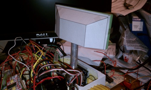
I have a few things on the associated blog but this is the first operational success with any of the subassemblies I've been building, with video included. That and I thought it interesting that my phone's cam can see infrared and hear ultrasonic frequencies. I knew the former but learned the latter while shooting this embedded vid.
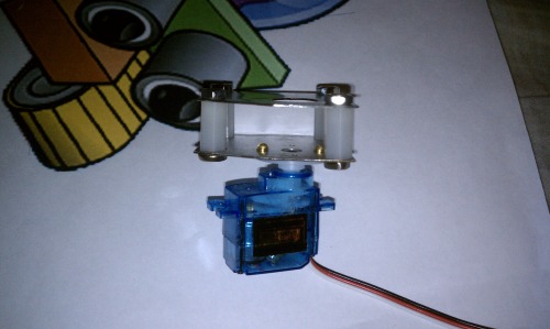
Anyhow the vid shows the ultrasonic object tracking head working nominally. Similar to mintvelt's Smooth Object Tracking, I just adapted it to a couple Maxbotix LV-EZ4's. I tried to stay true to the style that The Kings of LMR Robot Design might display ie, tounge depressors, paper clips, ample hotglue, and assorted bits from the junkbin.
As far as the rest of the build goes, I'm currently waiting for the second rubber track to cure, I need to re-grind the chassis for another attempt with the Bondo, and I must test the new thixotropic additive for the brain silicone.
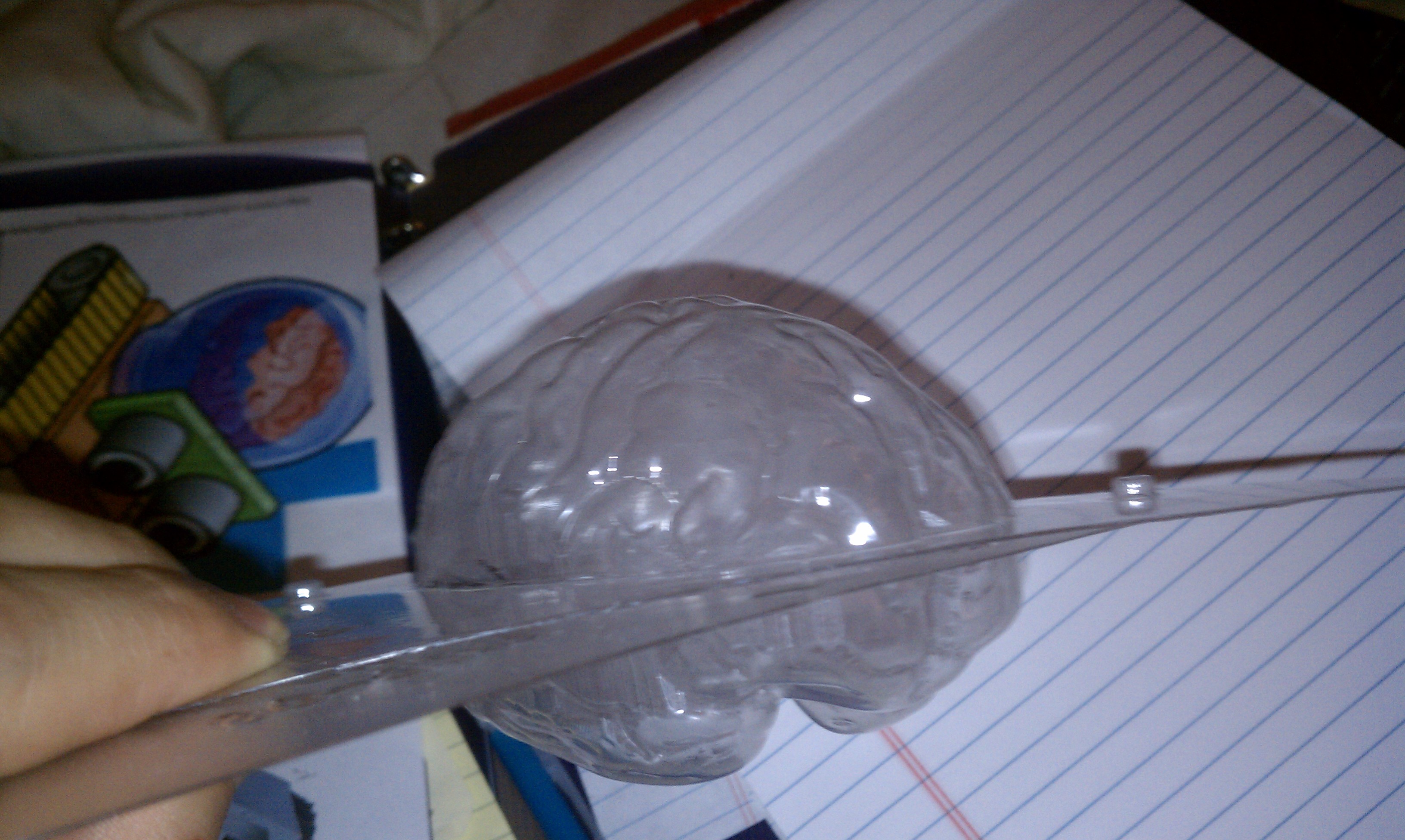
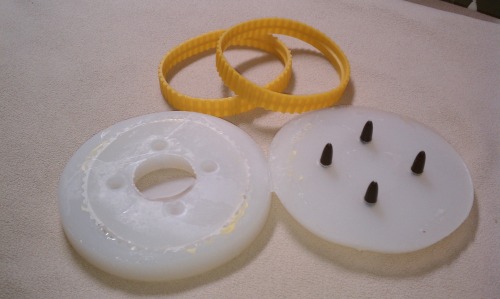
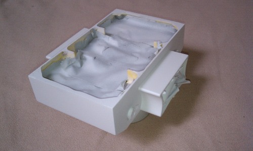
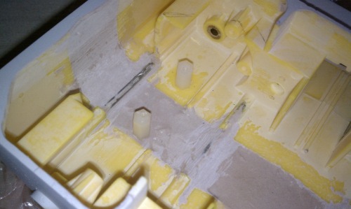
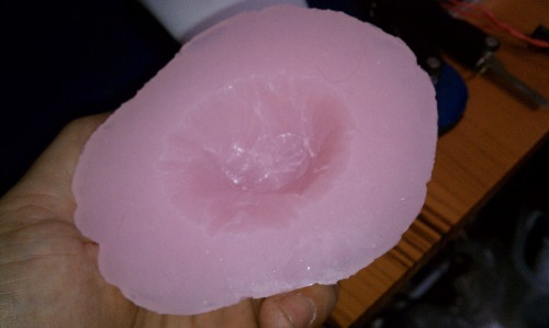
For the brain I skipped implementing my questionable sculpting skills and instead went to familiar molding techniques. The brain will be silicone cast in this 3D candy mold ~4" long:
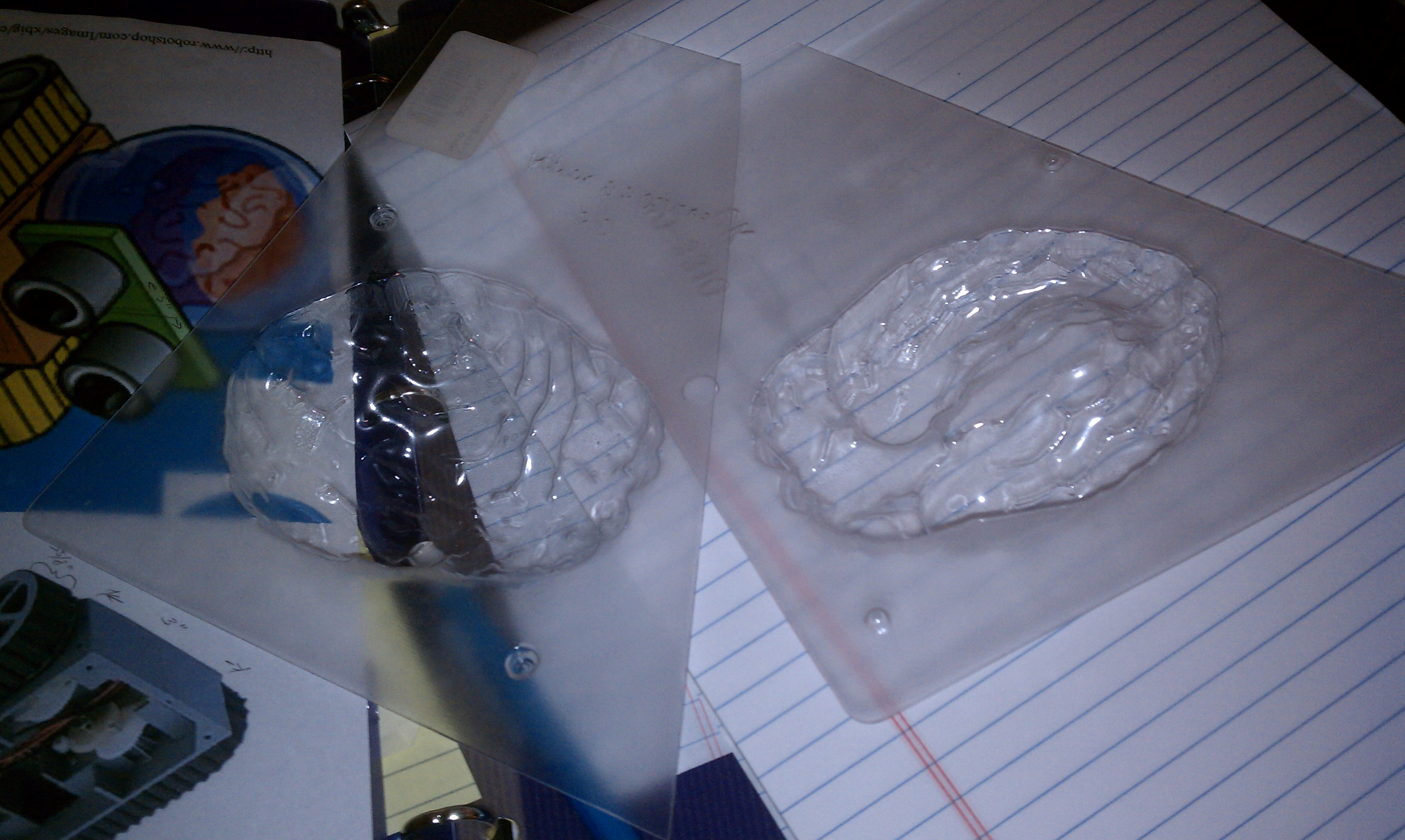
Use your imagination and see the future!:
Tin-based silicone is pretty good at tolerating foreign materials. Pigment will be from your ordinary acrylic paints:

Mixing a 10:1 base:catalyst batch with a touch of pink paint:

Pics of the stuff mixing:

Widening a pre-built tank chassis seemed easier than a scratch build. I went with the RP5. I split it down the middle and added some reinforcement rods made of 1/8" steel:

Closer shot of the rods:

Used some plastic sheet from the trash pile at work to form a base to catch the filler material:

With the plastic removed and some rough rasp work:
Underside:
Used the same plastic trash to make the brackets for the ultrasonic sensors:

Attached with Gareth glue, er, hot glue:

Mounted off-center to give the widest side view possible:
Top view of expected max travel before interference occurs from the inside of the housing (more plastic trash):
A pic up its six:
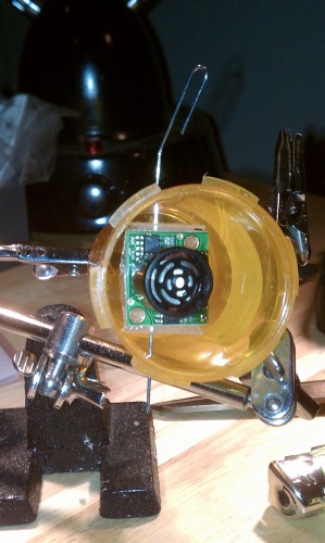
Single eye concept test; final stage. Showing max angle before interference occurs:
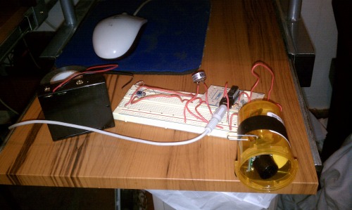
My high-tech setup:
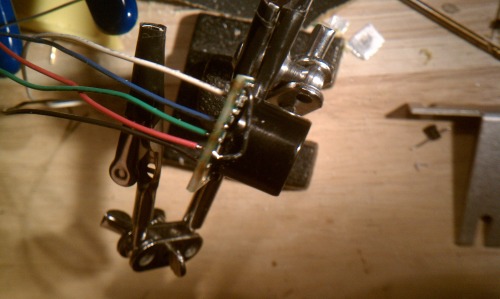
Got rid of the header I had been using (too bulky) and soldered the wires directly to the holes:
Use your imagination and see the future!:

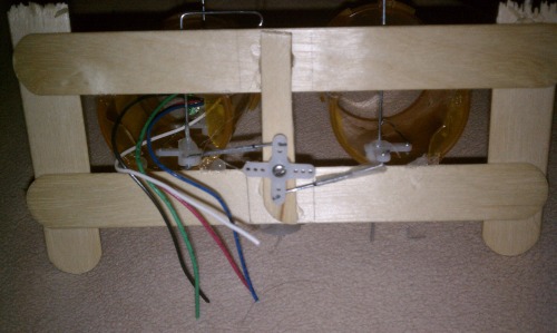
Easier to see the bellcrank setup in this pic:

More a pic for me so I can remember the linkage holes I used:
Casting authentic yellow tracks:

Several attempts later:
Chassis ready for primer:
Filled the OE wheels on the RP5 and made some low-profile hubcaps for authenticity. More uses for that same plastic trash:
I was having problems with the ultrasonic sensor setup (read forum post elsewhere) acting erratically. When I was tearing down the PoC setup I found I'd shorted the left signal wire and the daisy chain loop circuit. That can't possibly have helped. I'm holding out hope that it was the cause of my unsteady readings and the servo imbalance I was experiencing. Well, I hope at least one of the two gets eliminated when I get the prototype together.
Worked out all the IO expander/I2C stuff, the mp3 player/amplifier gremlins, and the power management situation. Got the individual codes all together at last and I'm ready to see if all the parts can play nice together. The problem is mostly with fabrication.
Currently progress is stalled on the servo brackets. The tolerances inside the chassis for space is incredibly tight, even with 9g servos. I think I finally schemed up a way to cram ten pounds of robot into a nine pound chassis.
Also stuck on getting the silicone brain just right. The standard silicone I chose is very fluid for a long time. I got some thixotropic solution to thicken the silicone but I run into bubbles and bubbles and bubbles that I can't get rid of ugh. Trial, error, and expended time will get me through it.
Mostly it's the servo placement though. With no eyes I can't test the rest of the system. The brain will just diffuse LED light and look sort of biologic but is not critical at this stage. I think this weekend I'll have the brackets fabbed up and can progress further.
Jul. 11, '11:
After chasing gremlins for a month or so I finally have three subsystems working together; servos, sensors, motors. Still in its beginning stages so it's a little rough still.
Viddy attached for your submission.
It's been awhile since I've put some good time into this project. A challenge deadline approaches so I'm putting this project into high gear. More info here (not sure why I don't see the normal blog link):
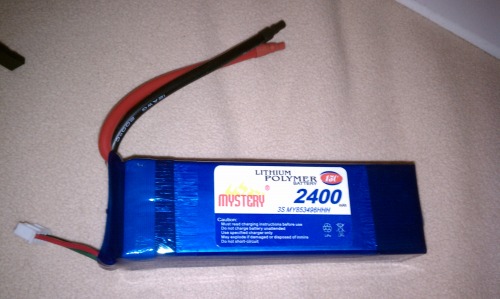
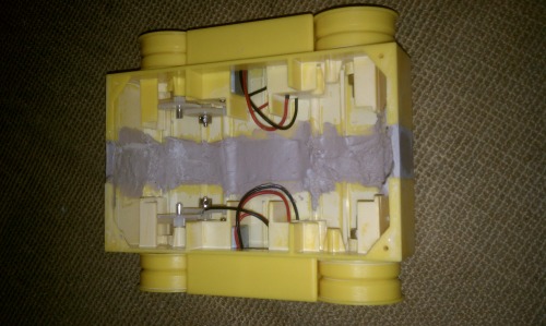
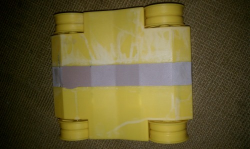
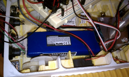
11.1V 2400mAh battery I went with. The charging plug leads were too short to make it outside the bot and the supply leads were all wrong for me. Some alterations had to be made.
No shrink wrapper.
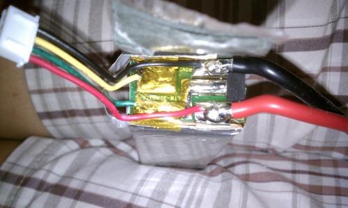
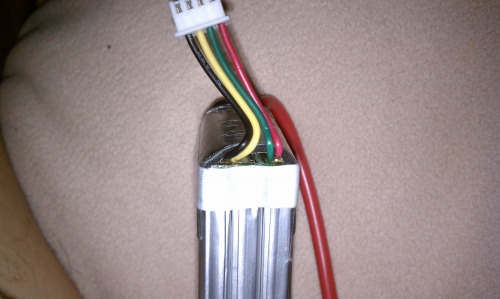
Tape peeled back.

Post alterations. Balancing plug leads exteneded and a JST power supply plug.
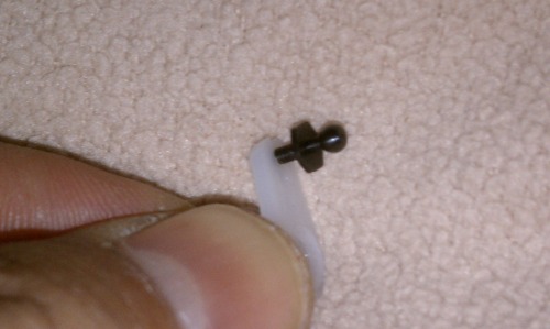
The smallest ball joints I've ever tried to hold onto! These will be used to control the sensor movements. I tried to use simple paper clip wire but there was too much play and slop. The hunt was on for these things,the smallest ball joints I could find, made by Du-bro, an RC airplane company. They screw into the servo horns from the 9g servos perfectly.
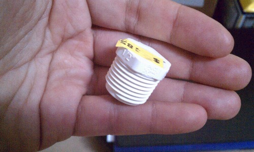
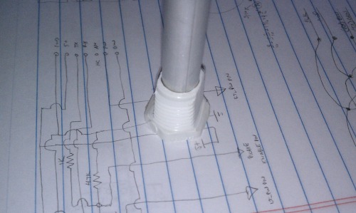
Needed a collar for the neck tube to pass through that would also attach to the back of the eye sensor panel with the lowest profile possible. Any extra height will reduce the room the eyes have to safely rotate and clear the brain jar behind it. I found this ABS(?) plug in the hardware store's plumbing section.

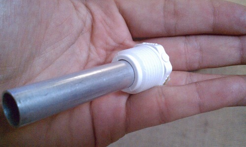
The 1/2" aluminum tubing from the hobby store fit inside with just a little wiggle room. Perfect.
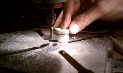
Ground down the threads on the side that mounts to the eye board and the side that will hold the grub screw.
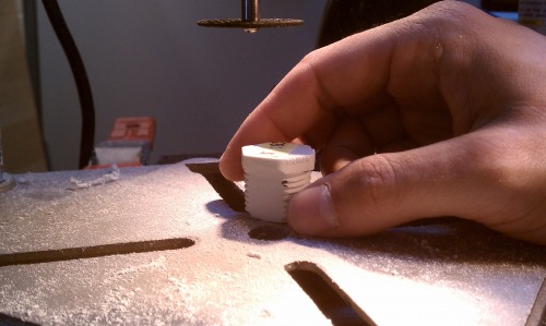
Marked the tallest the mount should be before it causes clearance problems with the bellcranks.
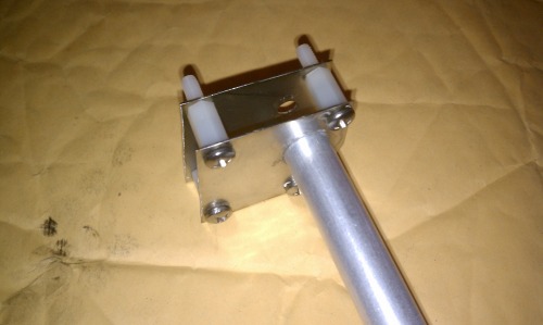
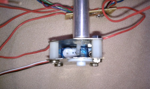
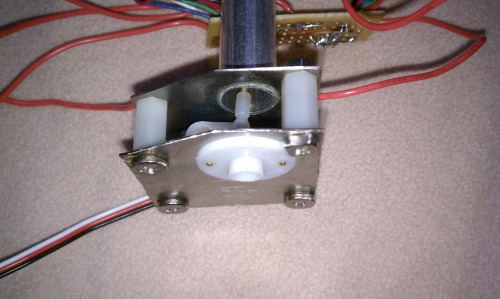
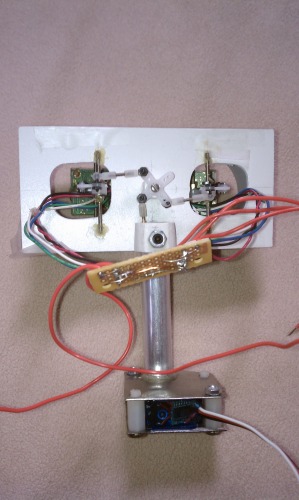
I needed a bracket for the servo to rotate the eyes and for the servo to move the ultrasonic sensors. Here's a pic of the assembly I went with made from some scrap stainless steel from my work's refuse.

I had to trim down the post to fit the rotation servo plus bracket under the lid. I had to route out a pocket for the bracket to travel through anyways but I wanted to keep the removal of material and strength to a minimum.
Bracket mounted to the servo horn with #0-80 screws and washers with no modifications to the horn needed.
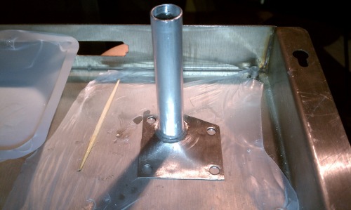
I drilled a hole with the diameter of the outside of the neck tube in the top plate of the bracket . I lined the bottom of a rigid and 100% flat steel pan with Parafilm and assembled the above pictured with a bead of 2-ton epoxy around the joint.


I drilled a hole and superglued a nut the size of a small set screw onto the back of the collar. I also drilled a small recess in the neck tube for the set screw to sit in.

Tah dah!
I took two of the standoffs I used for the servo bracket and trimmed off the threaded posts. I then drilled pilot holes for servo mount screws and superglued them (many layers) to the chassis.

Mock up of some of the more critical components when it comes to clearance and fitment.
Obligatory "LMRbot logo angle." :)
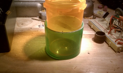
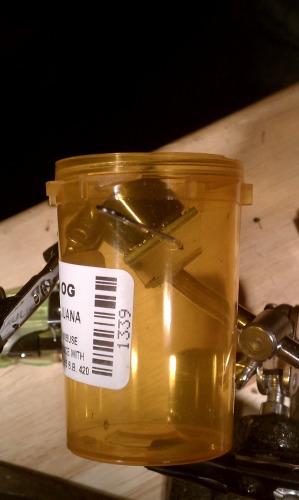
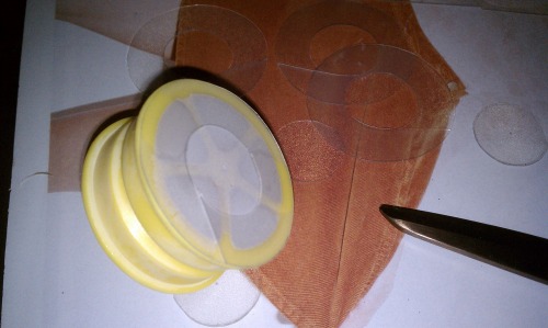
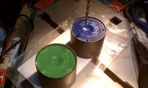
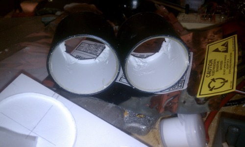
I wanted "angel eyes" that would flash when LMRbot spoke. I made a mold from a polypropylene medicine container that was slightly undersized when compared to the eye tubes I'd made.
I had to trim the inside container to the same height as the eye tubes. I will fill the gap with clear resin from what was the bottom of the containers and need the two to be flush with each other.

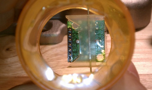
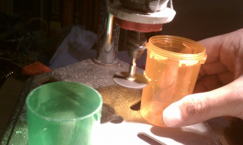
The original molding process of the containers left small nubs of plastic in the middle of the bases. They were just enough to cause the containers to mate together unevenly. I decided to drill them out and use them as alignment holes when the time came.

I did not want the clear filler material to extend out flush with the eye tubes. I wanted the tubes to extend out a bit, always giving a dark ring of contrast on the outside to emphasize the clear rings inside, no matter what the viewing angle. So I made a reservoir with some wadded up Parafilm. I will pour a thin layer of silicone into the reservoir and place the assembled angel eye molds into it. The silicone should provide uniform coverage to the tips of the eye tubes. Nothing like to stick to silicone except more silicone so the adhesion of the epoxy should not be a problem. The above pic shows the setup phase, getting the size right.

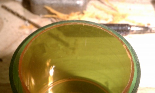
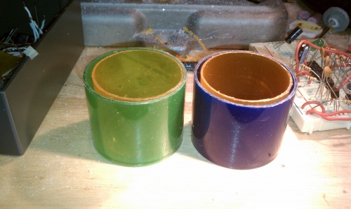
Next I primered (white) the eye tubes and gave the outside ends a couple coats of black acrylic paint. I also painted the very ends of the tubes black, trying not to get any black on the inside (you can see where I had to touch up my mistakes with white acrylic in the left pictured tube). I'm keeping the insides white to maximize albedo and to diffuse the LED's light patterns a little bit.
Four 11K mcd white LEDs will be used in each eye tube. To get equidistant holes I folded a sheet of printer paper twice, dragged a pencil down the creases, lined the middle hole up (first use of the alignment holeds) with the intersection, and marked the tube.
A 1/8" drill bit was used to give the 3mm LEDs some wiggle room.

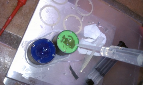
I leveled out the steel pan and poured a thin layer of silicone in the Parafilm reservoir. I immersed the ends of the amber inner containers in the silicone slowly and gently. Then I put the eye tubes in, also incredibly gently, while keeping the middle drill holes aligned (second use for the holes) to assure even spacing between the containers. This was allowed to cure overnight without disturbing.

Closer view of the height the protective silicone reached.
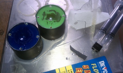
I found a 5-minute epoxy that claimed to be "clear transparent" as opposed to the "transluscent yellow" as seen on most of these types of epoxies. It is not 100% transparent as I suspected, that's ok. A nice feature was that this type of epoxy had a premixing tip which fit into the holes drilled for the LEDs perfectly and almost eliminated bubbles.
The next steps were hard to photo document. The process worked great with only one bubble in the clear epoxy. Epoxy doesn't stick to polypropylene or silicone so after a little wiggling (a lot of wiggling!) the inner amber container came out. The silicone also did the job in leaving a little lip on the eye tube. I then made some pockets out of duct tape and filled them with more epoxy to make some pockets/mirrors, if you will, for the LEDs to sit in and shine on. Then the clear epoxy interior was painted white to save every bouncing photon possible.
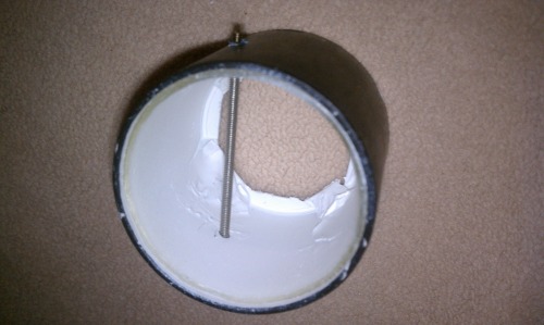
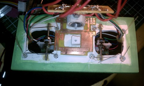
Needed some threaded rods for the sensors to rotate on. I will use some nuts and washers to give the sensors and adjustable mounting system


A pic of the back. Superglue (multiple applications) was used to attach the collar to the eyeplate. The tape is for temporary attachment of the eye tubes.
The ball joint just barely clears the neck tube, but it clears!
Back.
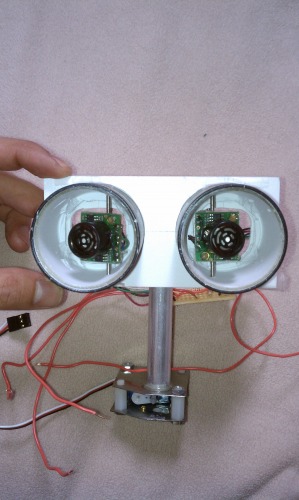
Front.
Several intermediary steps have been skipped here, but I remember them well :) I touched up and painted the eyetubes (inside and out). I fabbed up and painted the eye thing backplate green. I used a ball pointed grinder attachment to make nice round cups in the clear epoxy for the LEDs to sit in. I attached the eyetubes with four dots of black RTV silicone sealant in between each LED location. I etched a "headboard" that will serve as the permanent soldering point for all the components in the eye thing module. A wire harness will lead from the headboard, down the neck tube, and attach to the leads from the main circuit board.
Layout of the "angel eyes" LEDs and fitting the headboard PCB just right. You can see the old perfboard headboard prototype is still attached to the sensors.
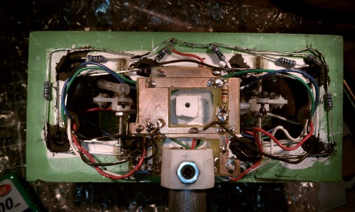
When the LEDs lit up there was stray light everywhere. I painted the backs of the LEDs white then painted on a coat of black. I had to blow the paint into the crevices and it sprayed all over the place.

You can see more light leaking out from between the Sintra plate and the backs of the eye tubes.

Left, untreated. Right, black RTV silicone filled gaps. You can see some light still escaping from some of epoxy mirror ramps in the tube that have a thinner coat of black paint.
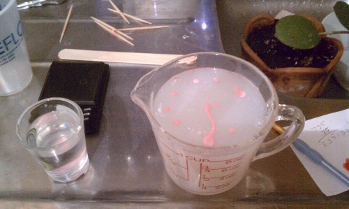
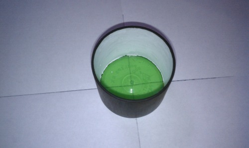
Got the two-part tin based silicone weighed out for both halves of the brain mold. Pink acrylic paint was added for pigment. The amount of paint was based off drips of paint/gram of silicone used in test pieces.
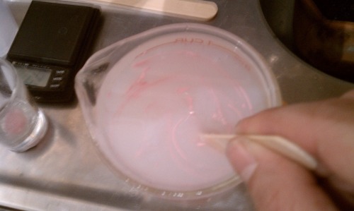
Catalyst added and stirring VERRRRRRRRRY SLOOOOOOOOOOOOWLY. Even then the bubbles are impossble to keep out. Without a degasser it makes for a lot of shaking of the molds to make bubbles rise to the top.

After hours of shaking and banging (until the silicone got too thick for bubbles to rise) I made a couple beds out of towels for the two molds to cure in overnight. I actually let the molds cure for 24 hours as the thickness made me concerened overnight was not enough. No additives were used, other than the pink paint.
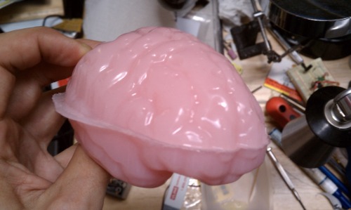
Brain, pre-trimming.
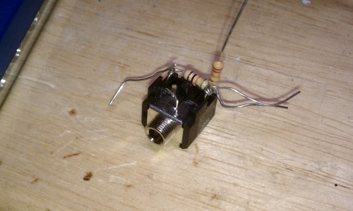
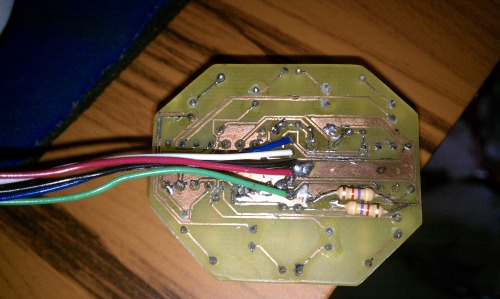
I needed a jack for ineveitable reprogrammings of the 28X2. It would be a huge hassle to dig in and get it out for reprogramming if/when the time comes. PCB room (at the time) was so tight I freeformed the resistors necessary right onto the jack itself.
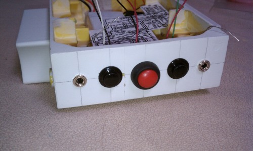
Left to right: Programming jack #1, volume up button, panic button, volume down button, programming jack #2. The two jacks are leftover from when I had two PICAXEs on board the main PCB. Now that I've reduced it to one 28X2 I will replace the left jack with a rocker switch for power.
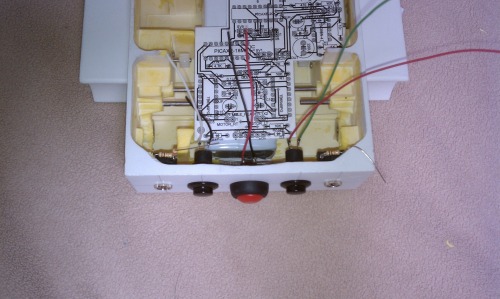
Tight clearances applicable to the buttons as well.

With three linear regulators and everything else under the hood I thought some ventilation would be advisable. I found a 25mm 5V fan that will fit into the bot. I drew out a grid and drilled 1/8" holes on opposite ends of the chassis for incoming air and exhaust air. The regulators will be located next to the exhaust ports for efficiency.
That's all for now, more to come, of course.
Feb. 15, '12 -
I wish I had more to show but this last month was spent on getting the glowing brain devised and tested. There were many obstacles but I finally got it to be an acceptable piece of work.
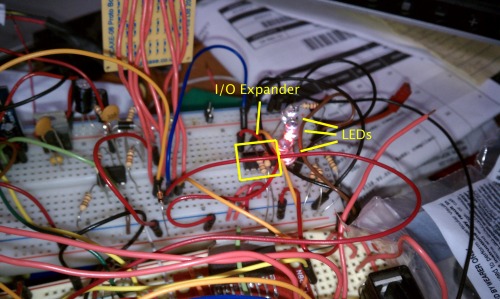
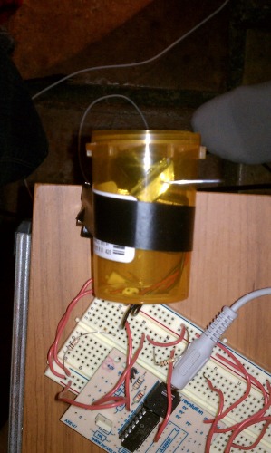
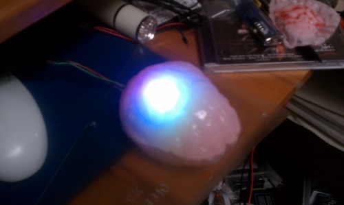
First was getting an individual RGB LED setup working with the IO expander.

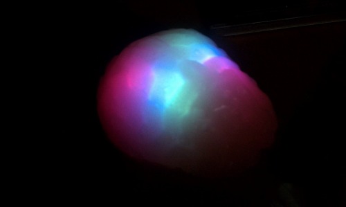
The layout that caused me such grief. I liked how the RGB LEDs made a nice white light that gave off a warm pink brain glow.


Shots of the red, green, and blue LEDs cycling through. The blue and the green were just too dim.

Attacking the upper hemisphere with a razor blade. The scalpel shaped one worked best for hollowing the silicone out.
I needed to remove more material than this but you get the idea.

After many designs and oopsies, I present the working "brainboard." The two jumpers were from the I2C resistors that were installed in series instead of as pullups.
The resistors were tacked onto the back. When I was bending the LEDs into position it loosened some of the tracks from the board. You can see where I used some cyanoacrylate glue over the LED through holes to help avoid that from happening to all of them.

Where the board will sit. I will route the wiring through a hole in the bottom of the brain. I decided to wire in a serial connection for reprogramming after all, in case anyone was counting wires. I need to determine where the power switch for the bot will be now.
Startup/Warmup LED pattern. It's actually all the RGB LEDs but they no longer make a nice white light due to the new design I had to go with. It woked out alright though.

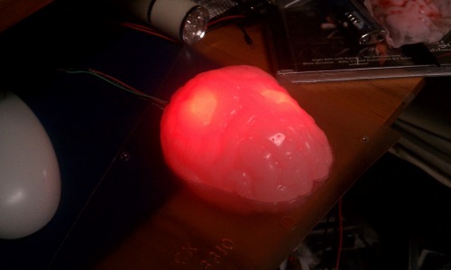
When you get too close to the bot it will rapidly cycle between the red and blue LEDs, police siren style.
When looking for people the LEDs will light up individually in a circular chaser-pattern. Hard to capture in still photos.

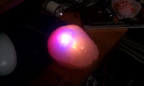


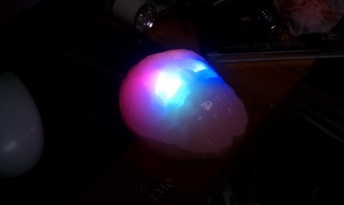
Some random shots of some of the random patterns that come up while the bot is locked onto a person.
There is a disco beat pattern for when the bot plays music tracks but I'm having problems with the jukebox routine so no pics of that. Those look pretty much the same as the above because I share some coding but alter the timing to make things look unique. I'll save that for the video I suppose.
I have been comtemplating how to add the final touches to the brain as well...
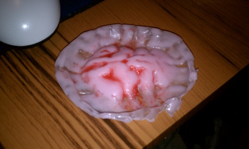
This is some tube adhesive silicone that I mixed with some red acrylic paint. It set up fast but I used a good deal of paint. The water content helps cure the silicone faster. I think I'll try it with the tin silicone mixed with some of that thickener I have.
I also needed something to cover up the ratsnest going on behind the eye sensor plate. The clearance between the eyes and the brain jar is very tight so I needed something besides freehand drawing to design the cover. I guess I should finally try out Sketchup...

A pic of the 3D rendering. I went with an open underside, which is sort of the angle you're looking at.

The printable 2D version. I ended up taking the measurements of each section from the 3D rendering and redrawing this 2D version. I'm sure there's a way to flatten out a 3D image but I couldn't tell you how.
The papercraft version of the cover. I'm waiting for the right plastic trash to salvage for this piece.
I also decided to simplifiy and downgrade power sources somewhat with a 2200mah 7.4V Lipo. The 11.1V was just too big and forced the use of a regulator for the motors. This voltage will allow me to power the driver directly from the power source instead. Hopefully this will have enough runtime to entertain.
The next step is routing the wires from the brain to the inner compartment of the robot. It looks like I'll have to modify (again) the circuit board to accomodate the design I've settled on. But there will be almost no fear of brain juice leaking onto the L293HN, which is a preeminent fear in my mind.
March 15th, '12:
Been busy but not a lot of documentation. My plate has been very full to say the least but I keep plugging away and here's what I have to show for it :)
I reached a point where the dragging assemblies became a nusiance to look after. First thing to do was to make some more circuit boards. I needed two more; one for the voltage regulators and power distribution plugs and one for the main circuit. The power board was easy and a single-sided unit:
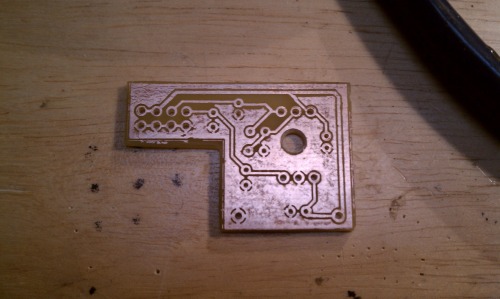
Only a couple errors (as usual) but nothing fatal. I increase the clearance between signals and on the plane polygon compared to my Hexaspider and the 08M2 brainboard etchings. There were no errant short circuits this time with the extra clearance.

The main ciruit board.
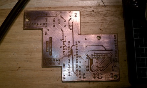
Potentially an exhaustive exercise in futility. I've vested so much heart and time into this production that I refuse to give up on it. So far I've soldered all the vias (16ish?) and the 8 and 28 pin sockets. A lot of work.
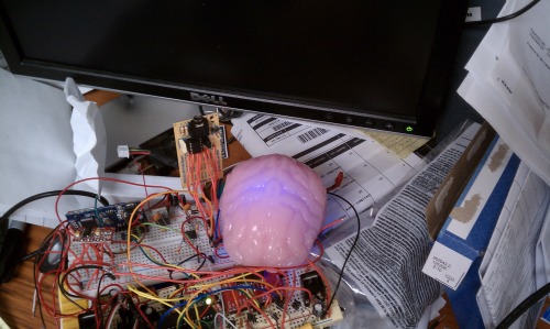
It's in there...
I've had to do a lot of work to figure out wiring inside the bot, how to get the brain tank just so, and some more nigglings with the brain itself. Mostly things not able to be photographed or not worthy enough for it. Trust that I've been busy, though.
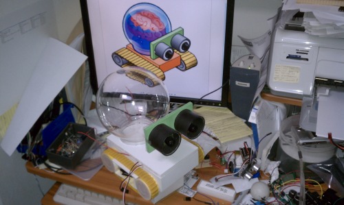
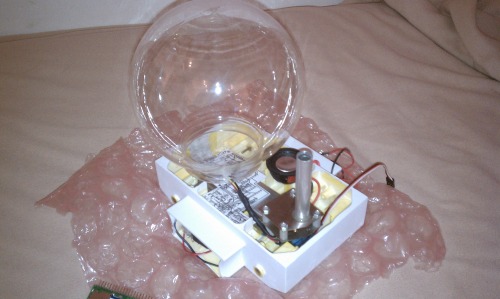
I needed a piece of visual candy to encourage me through some of these trials. I ripped apart enough to reassemble enough of the partially-completed parts for me to remember The Final Vision. I just thought I'd share :)
October 12th, '12:
This bot is a labor of love that I haven't really stopped working on. Several things have taken precedence but this project is still ticking on.
Hardware:
I was dissatisfied with the audio output of the amplifier I'd chosen. After much research and deliberation I decided to use the TDA7297 powered directly with the 7.4V lipo. It should produce about 2W @ 8ohm which is exactly what I want. I ordered a kit from eBay for the components but I need to make a custom PCB that will let it fit in the chassis. It's been EAGLEcad'ed so the hard work is done.
After finally getting that last element solved it was onto wiring harnesses. I have gone with almost half a dozen different connectors that are suitable for whatever application they're being used for. I'm slowly getting though them. So far I have the MP3 harness made, the switches have their cables, and the power harness plus switch is complete.
The new amp also changed the power distribution network so I had to redesign the voltage regulator board again. It has also been EAGLEcad'ed and waits for my attention.
I've succesfully gotten the two brain hemispheres attached together and it passed the waterproof test. I need to do some touchup on parts of the seam where the two halves meet and I need to get the red veiny stuff applied.
Software:
Initially LMRbot WS2 was going to speak english and make R2D2 sounds. With the inception of LU2MI2 I kind of had to get rid of the George Lucas effect on this bot. So I've been trying to think of as many trite phrases and greetings to make up for the amout of R2 sounds I was using.
I've also found almost half a dozen robot songs to use. Hopefully the hardware will sort itself out so I can troubleshoot why my jukebox routine was not working right.
I also uploaded the object tracking code for someone on YouTube. It is only for the two servos and two Maxbotix sensors; it doesn't include any of the motor control for distance regulation.
Shop Notes:
Since the fabrication of the main board (so messy!) I've given in and gotten genuine toner transfer paper, a $30 laminator that Hoff was using to make his PCBs with, and I've gotten some H2O2 and HCl for a less toxic etching process. The voltage regulator board and the audio amp board are slated for production this weekend. I'm hoping it goes smoother and is more accurate than my old ghetto-fabulous procedure. If these PCBs go as well as I hope I might seriously consider remaking the main board despite all the work I've gone through. It's very bodgy right now and I suspect it will fail intial testing. An unsavory thought but I think this step back could very well be a step forward as well.
Follow you around, generate noise and lights, make subtle suggestions.
- Actuators / output devices: DC motors (2 x 280-type)
- Control method: autonomous
- CPU: PICAXE 28X2, PICAXE 08M2
- Power source: 11.1v Lipo
- Sensors / input devices: Maxbotix LV-EZ4s, panic button, volume buttons
- Target environment: Open areas
This is a companion discussion topic for the original entry at https://community.robotshop.com/robots/show/lmrbot-ws2-edition

