I need to finish some things, then i will put the complete project on web. I still have some technical and electrical problems which i am figuring out. Programming is not a problem, it's fun.
EDIT:
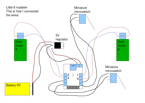
I have put a center front wheel and a switch to control battery. Pictures soon
I saw that in the specification of this motor (GM9) is written that it can run on 12V. So my question is how do I get that much Volts from the microcontroller to the motors.
I need some suggestions because now it runs on 1.75V on one motor ( 3.5V total output from the microcontroller ) and it’s slow
I don’t think you can easily run a separate voltage for a Picaxe 8 board. The larger project board for the Picaxe 28 gives you the option to run two voltages (V1 and V2), but I don’t believe the Picaxe 8 board does.
You could do something like add a couple of DC relays. The relays would let you use the motor drive outputs of the Picaxe 8 to energize the relay coil, and then drive a higher voltage to the motors themselves.
first of all you can place them parallel, and not in series like they are now. That way they would both receive 3.5V
BUT, if you want them to receive more voltage you should check out the motor driver’s datasheet to see if it can accept more voltage for driving the motors.
I don’t understand what you mean by putting them parallel. I connected the left motor to one output and the right in the another output on the board, just like it is described in the manual.
I checked the motor driver’s datasheet and I’ve seen it can run on 12V.
i thought it war running in series because you said each motor was receiving half of 3.5V. Did you measure that?
As for the motor driver, since you’ve seen it can receive more voltage you could try connecting it to unregulated supply, but be careful about the pin you are connecting, else you could cause damage to the chip (this to say: double check the datasheet before you make the connection).
You could use additional driver (schematic and PCB made by me):
By 5V I mean the same power source, that you use for arduino. 12V is a power source, that you want to use for motors. On PCB - ARDUINO_X is a place, where you connect motor-output from arduino. MOTOR_X is a place, where you connect your motor.
The "cross" inside PCB is a GND ("-" on your batteries).