

This bot is from the "Arduino Robotics" book. Great book by the way, I would highly suggest it. The first three chapters is a crash course on Electronic Engineering, and it was needed to get through most of this. To begin with I ordered all the parts. I purchased them from Digikey, Adafruit, RadioShack, and Hobbypartz. Great sources for all sorts of electronic parts, equipment, and tutorials.
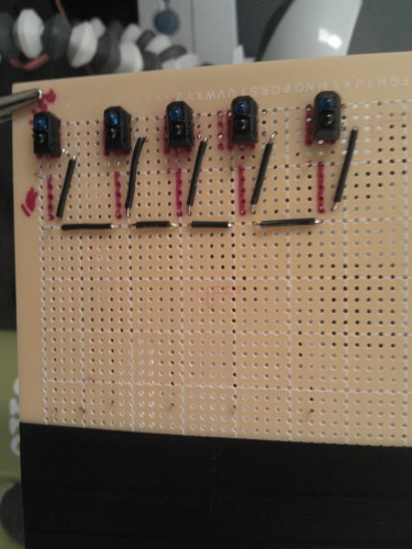
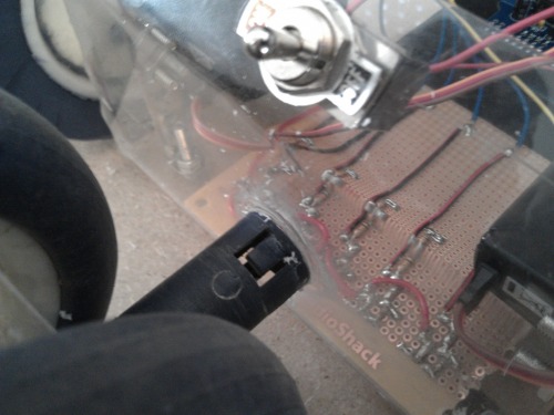
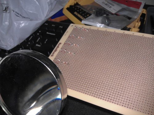 Lead off with marking the positions with red marker where I will be putting everything. I should have waited till I actually received the IR Emitter/Detectors, but I was too excited and soldered the resistors on first. The top 5 are 150ohm resistors and the bottom 5 are 10k ohm resistors. Once I finished those the next day I received the emitter/detectors in the mail. And then I found out that I sorta had it backwards and had to redo some of the resistors. Not a big deal, but this is my first bot and it's ALL a learning experience.
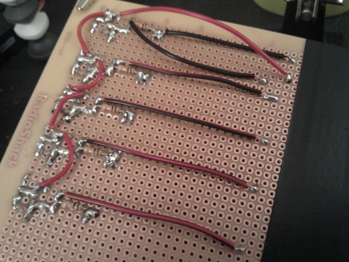
I then connected all the pieces. Attaching all the +5v and GND to their respective spots throughout the board. As well as solder for the outputs. It didn't turn out very pretty, but I beleive it will work!
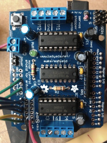
I soldered together the motor shield board I purchased from Adafruit. That was fun and fairly simple. looked a lot better than I thought it would have, considering this was all my first time really soldering anything. The outputs of the emitter/detectors are then soldered to the motorshields analog pads 0-4.
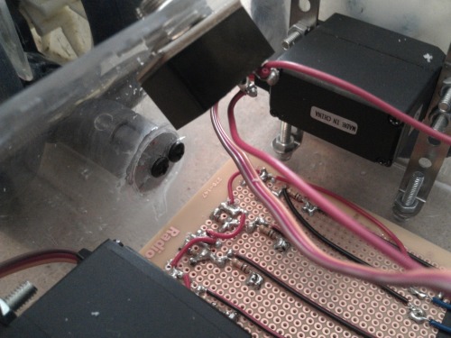
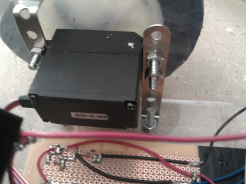 I removed the potentiometer and the circuit board inside the hobby servo motors to allow 360 movement for the wheels. I attached the motors using pieces from a erectiset I bought from a thrift store for $4, I knew it would come in handy.
 I used left over acrylic I had lying around from a submerged cooling tank I made. I have a soldering iron/torch which was used to heat the acrylic and bend it to form the frame. Fairly easy to do, just heat a line(keep the torch moving back and forth) and when warm enough it will start to bend on it's own. Then place it up again a 90 degree angle and let cool down.
 The wheels are from a stoller I bought for $5 at a thrift store in town. I sawed off one of the legs of the rotating wheels up front to use the swivel. My buddy Cole has been coming over helping me out with the frame, he ended up screwing a wooden dowel, then screwing and super gluing it to the front of the frame. It looks unique, but it's promising.
Unfortunately these pictures have the board completed, but you can get the best of it here. You can also see my mistake/not mistake on the bottom right side of the second picture. I say "mistake/not mistake" because I had originally soldered my 7.2v battery to the two pads right next to the Servo input pins. After I plugged it all in the wheels started spinning and then a poof of smoke came. I immediately it shut off. I tried searching for the source of smoke, but with no luck. The pictures here are after I had plugged it all in. I consulted the Adafruit forum and one of the techs gave me a few ideas, one being to disconnect the location of the 7.2v battery I had originally soldered to the pads and connect it to the input terminals. Then, I had explained everything in more detail he suggested powering the Arduino seperate fromt the motorshield, so I have to reconnect it to those pads and plug a 9v batter to the DC input on the Arduino. **I did not attach a 9v battery, with the jumper pins the Arduino is powered and it's working...for the most part.
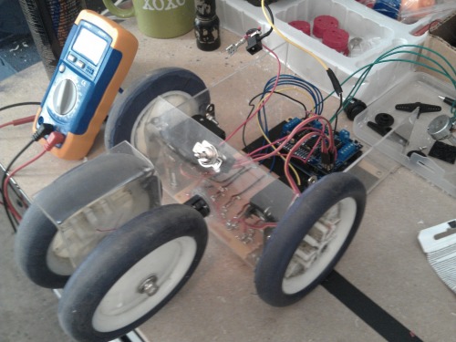
 I ended up mounting the battery to the front-end, to better counter balance everything. We put the wheels so far up front to get a tighter turning radius. I think it turned out pretty well. I just have to wait for the silicon adhesive to dry and I can officially test out. But here is the finished product, I will post a video of the first time driving. PREDICTION: it will spin in circles because the motors are backwards, but I don't want to mess with it just yet. I'll be physced if it spins in circles at this point. ;)
Marked as complete, because ALL tests check out, but I broke one of the emitters of the sensors. But, the other sensors check out as well as the motor shield. When I get a new sensor I'll post a video of the succes to better reinforce it.
Special thanks to DanceswithRobots, and ChrisCarpenter for the tips and helpful hints.
FIRST OF MANY BOTS...COMPLETE!
Supposed to follow an electrical tape line.
- Actuators / output devices: 2 servos modified for continuous rotation
- CPU: Arduino Uno (atmega328)
- Power source: 7.2v and 9v battery
- Programming language: Arduino C
- Sensors / input devices: 5 x IR emitter/detector
This is a companion discussion topic for the original entry at https://community.robotshop.com/robots/show/linus-robot-my-first-bot