

My heads been buzzing with project ideas lately and one such idea revolves around a light painting (aka light graffiti) robot. Too often I don't follow through with my ideas so in order to try and progress this one I thought I'd build a prototype. The prototype is built with bits and pieces I have lying around: two regular size servos, some balsa wood and zip ties. An LED (or two now three!) is mounted to a socket at the end of the arm. I'm using my Arduino Mega ADK and a Wii Nunchuck to control the arm.
Light painting, or light graffiti, uses long term exposures (where the camera sensor is exposed to the light from the scene for 30 seconds or more) and allows for various effects with light sources moved through the scene. In this case the camera is set on a tripod and the light painting arm moves an LED around to draw a sphere. Other methods of making these light orbs include swirling an LED around on the end of a string or attached to a fixed rod or pole.
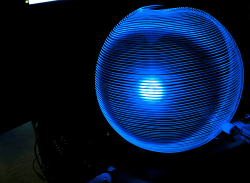
My first light orb. No fancy analog control of the LED brightness in this one though.
I wasn't finished with just making a light orb. I played with varying the brightness of the LED as a function of the position, then I tried reproducing images on the orb. Images were converted from png to an array of bytes for the Arduino using a simple Processing sketch.
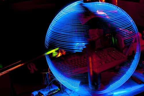
Orb with brightness dependant on position.
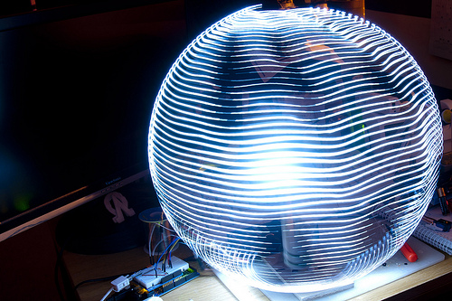
Light orb displaying an image (reads 'Hi').
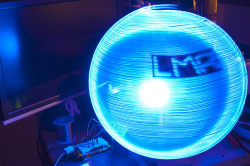
Smoother, more definition and 100% more LetsMakeRobots!
Update 24/09/12: Added a stripboard with three LEDs (Red, Green & Blue) to the end of the arm allowing for colour blending and hopefully some full colour images (once I figure out how to get around the memory limits).
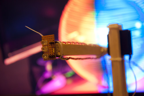
Three LEDs are better than one! Red, Green and Blue LEDs on stripboard.
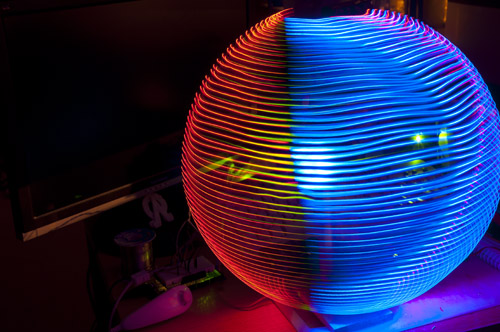
First colour blending result. Needs more green I think.
Update 30/09/12:
Well I've moved away from processing images in Processing and storing them in the Arduino C code (though I'll leave the Processing sketch at the bottom of this page in case it is of any use to anyone). The photograph below shows my current setup in which the Arduino Ethernet Shield is used to read a micro SD card. Images are saved in bmp with 24-bit colour and the sketch on my Arduino reads out the individual pixel data byte by byte. To do this I swatted up on the bmp format using the wikipedia entry and the Arduino SD reference (as this was my first time experimenting with the Ethernet shield or reading SD cards).
To begin with the file name was hard-coded in the Arduino sketch but I wanted some way to select from any of the bmp files on the SD card so I added an LCD (Nokia 3310 only needs 5 digital pins and 3.3v power) and included the Wii Nunchuck, though adding some push-buttons would have sufficed. Finally, I added a wireless trigger which I wired to an opto-isolator. The wireless trigger can either be used to trigger a flash or, as I'm using it, remotely control the shutter of a camera.
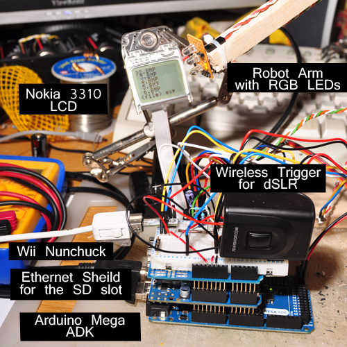
Current setup, a bit untidy but this is only the prototype after all.
I intend to use an SD Shield to tidy this up, soldering onto it connectors for the servos, Wii Nunchuck adapter, wireless trigger and LED cables. Hoping to downgrade to an Arduino UNO or similar for this project as I don't need all the extra pins or USB Host of the Mega ADK.
Update 01/10/12:
Received my BlinkM RGB LED today. I also received an UNO and SD Shield but will be leaving them in the box for now as I play with the code. So far I have the I2C comms working fine and colours update nicely. BlinkM is a bit too bright for such close quarters, I'll look at toning it down in code. I do have one major issue though, the Arduino is now locking up (no more movement from servos, LED constant colour). Possibly a memory leak or something.

I can complete some light paintings without trouble but not others. This is one taken with a rubber band to obscure the transparent body of the LED which was leaking light and smudging the image.
Update 10/10/12:
After spending several evenings fruitlessly trying to get the code to work on the Arduino UNO I gave up and instead concentrated on getting the microSD shield populated with the connectors I need to provide a more permanent (and I was hoping a more compact and tidy) home for this project. I've cut down on the number of jumper wires however still need a few as I need to connect the shield to the correct pins on the Mega.

Arduino Mega ADK and populated Sparkfun microSD shield
I've spent some more time on the software, adding a menu system to allow for changes to some parameters which were previously hard-coded. In the image above the menu is in the Resolution tab, having already selected a file from the File tab. Here I can chose to have a canvas larger than the image (resulting in a light painting that does use the full range of motion of the robot arm) or equal to the image resolution to strech the image out to the extremes of the robot arms space envelope. The next tab is Exposure, where the duration of the light painting is estimated and options are provided for changing the delay experienced at each pixel etc. The final tab is 'Settings' which is for misc options and currently holds a toggle for switching to an alternative function for the actual painting, which reads in an entire row instead of reading the SD card a pixel at a time.
Using some thin sheets of balsa wood I made a cover for the BlinkM to block out the light leakage. The LED still needs a diffuser as I'm still getting the lensing effect which is most evident in the first photo at the top of this page.
BlinkM with balsa cover
Processing:
Simple sketch I threw together to grab the pixels from an image and turn them into an array for the Arduino sketch. Last updated 25/09/12.
int x_res = 32; int y_res = 32; String filepath = "heart32.png"; // hard code image name/path // load image // read pixel by pixel and write value to text file // format as arduino array // copy and paste array from Processing output into Arduino sketch // sketch runs through the array and analog writes to the LED pin void setup() { size(x_res,y_res); PImage b; b = loadImage(filepath); image(b, 0, 0); print("static const byte image[]["); print(x_res); println("] = {"); for(int y=0; y<y_res; y++) { print("{"); for(int x=0; x<x_res; x++) { // use one of the following lines: print(int(brightness(get(x,y)))); // print(int(red(get(x,y)))); // print(int(green(get(x,y)))); // print(int(blue(get(x,y)))); if (x != x_res-1) print(","); } if (y != y_res-1) println("},"); else println("}};"); } }void draw() {
}
Draws light trails in long exposure photographs.
- Actuators / output devices: 2 servos, LED
- Control method: pre-programmed route
- CPU: Arduino Mega ADK 2560
- Sensors / input devices: microsd, Wii Nunchuck
- Target environment: indoor
This is a companion discussion topic for the original entry at https://community.robotshop.com/robots/show/light-painter-arm
 Thanks!