Greetings!
I’m having problems with a Lidar-lite v3 module. Running the LidarLite Library’s “GetDistanceI2c” sketch returns only the number 1, line after line, like this:
1
1
1
1
I have tried two different Arduinos (a Mega 2560 and a Pro Mini) with the same result. Running the “i2c_scan” sketch reports the module at the default address of 0x62.
If anyone else has solved and/or had this problem or has any ideas or suggestions, I 'd appreciate hearing about it.
Thanks,
Bud Ryerson
San Francisco
415-282-5268
@budryerson
Can you please give more details about your setup, how you are using and powering the Lidar-lite?
If possible, pictures would help to troubleshoot.
Thanks for the reply. That’s more than I’ve gotten from Garmin.
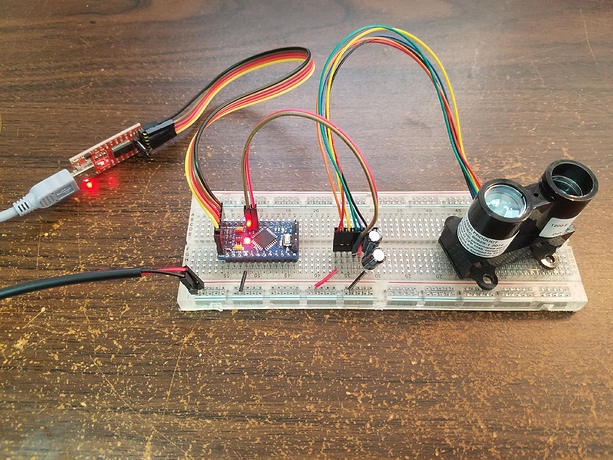
The test setup is real simple. The power supply is a 5V1A wall glob. The power looks clean. The two capacitors are each 330uf and in parallel across the +5V connection. I’ve tried between 330 and 2200uf and nothing makes any difference.
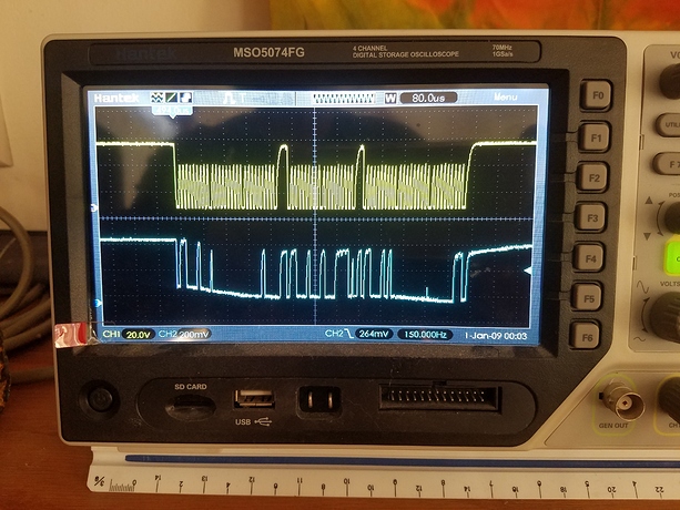
The SCL (yellow) and SDA (blue) signals are shown below. The SDA isn’t as perfect as I would like it to be, but looks to be within spec. You can easily the ranging command followed by a read command and two bytes of data.
I bought the damn thing thinking it would be more accurate and easier to use than the Sharp GP2Y parallax IR sensor I have been using for my robot. I could not have been more wrong.
@budryerson
Hi there, I am just another user as opposed to RS staff, but have been using the lidarlite for a while now. They can be a little temperamental for sure. I’ve had success with the arduino nano and uno so can confirm those boards work.
Something strange I did find was that my (now fairly old) lidarlite would not work if I powered it separately. That is if I gave it its own 5V supply, it just would not turn on. It needed to have the power come from the arduino. There is quite a lot online about how previous versions were very sensitive to inrush, which is why they recommend the 680uF cap, so there is something around power usage that affects the unit. Their wiring diagram also shows the unit connected to the arduino power.
Though it makes little sense as to why that should be the case (maybe something around regulation) if you change the lidarlite power connections to the arduino 5V and ground, does that make any difference? It may also be that a DC/DC buck/boost between the wall supply and the lidarlite might help.
Hope this helps!


