A Robotic Lawnmower
Update 20131213: Lawna had her drive motors upgraded to cope with wet grass and leaves. These give much more torque and a faster speed over the ground. I've missplace an eye somewhere !
Update 20131102: OK, I can't help myself..
I had finished Lawna and been busying myself with beacon experiments. The summer was over so Lawna was due to go into hibernation until next year. However, its been mild, the grass keeps growing, the lawn is covered in leaves so there is work to do. So when it finally stopped raining, I set Lawna out to do her stuff and found a problem. When the grass is wet, the wheels skid, the robot is not heavy enough to gain purchase. Ok, the grass is pretty wet, but this is not good.
I have considered adding spikes to the wheels so they gain more purchase, but as the battery life is so good now, I'm considering beefing up the drive motors to get extra weight, extra torque and perhaps even extra speed to help ot plough through piles of wet leaves. I know the mower was originally designed just for a maintenance cut but having to decide what is 'good grass to cut' and 'bad grass' is not really labour saving. Bad grass means I have to mow the lawn and that is not the plan. The new motors are physically much bigger and I have limited real-estate to play with so there will be some surgery required...
Update: 20130924: The final installment
Update: 20130924: The final installment. After installing a new cutting motor, final tests were made to see how Lawna performed. Battery life has been greatly improved. The blade had to be modified slightly and a new front bumper mounting system was added. This gave much better cutting performace and made for a more resilliant bumper. I'm happy with Lawna performance so am marking the project as complete and going to sit by the window and wait for the grass to grow!
Update: 20130821: More details on new blade and implementation of a simple battery charger
Update: 20130813: Upgrade to the cutting motor to reduce power consumption - See the bottom of the page.
Well, its been a long time since I had any time to get out the soldering iron but making a simple lawnmower was a good thing to get the children involved with. As usual, the painting was the part they liked best and dear old dad just did the grunt-work !
After delving into robotics briefly, it became apparent that it should not be too difficult to make a small, self propelled lawnmower that could fumble its way around the grass and cut it while in the process. A simple prototype would have very little intelligence, just a couple of bump sensors to tell it to stop and go elsewhere. This ramdomness should hopefully end up mowing the whole lawn but I suspect large tufts would get missed, but you never know till you try. If nothing else, it could mow under the trampoline which would certainly be useful.
Goal
Build a simple autonomous robotic lawnmower
If the lawn is cut short, a small robot should be able to just cut the tips of the grass regularly, keeping it short and removing the need to collect grass clippings; well not regularly anyway. This would mean the blades could be small and the torque required would be much less than its larger, human-propelled cousin. So its a maintenace or grooming lawnmower and not intended for major weed removal !
Requirements
The initial version will just use bump sensors. I may more intelligence and sensing after seeing how the initial version performs.
It would make sense to mount a solar panel over the mower as this can be used to charge the battery. Due to the small size of the machine, any solar panel that could be mounted would be very small so it may take several days to recharge the battery. However, mowing the lawn once or twice a week should still be sufficient to keep the grass under control.
Given the mower brains will be a microcontroller, I believe monitoring battery voltage will be a good investment of time. The mower can be shutdown when the battery voltage drops below a threshold to prevent damaging it by excessive discharge. This opens the door to solar charging or even navigating to a charge point. However, these are all nice to haves but distract from the initial goal so I'll investigate them later.
Time is always against me, I have very little free time so I decided to use an arduino uno as the brains of the system as it is easy to setup and program, and has a host of third-party libraries.
Initial Experiments
First and formemost, the robot needs to cut grass. With this in mind, I set about trying various motors and small blade arrangements. I decided a 12V motor run from a small lead-acid battery was the best option and set about doing some experiments.
Blades
I seem to spend a lot of time playing with blades, be they wind-turbine or mower blades!
The blades are a problem, they need to be sharp but not so sharp they cause major injury if the mower rolls over your foot. Initially, I tried a set of sickle-shaped plastic blades used by some strimming machines. I attached three of these to a central hub, attached it to a motor and sat on my hands an knees mowing the lawn much to my wife's amusement. Even with a fast rotating motor (10000 rpm), the blades did not really cut the grass, but rather batter it into submission, fraying the ends and not making much of an impression. I did consider changing them for stanley-knife blades but thought this was too lethal a machine to even contemplate.
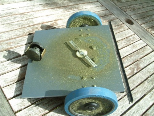
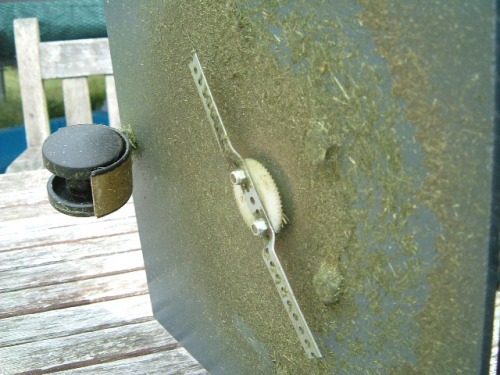
I then made a blade using a 3mm piece of steel strip and ground down a cutting edge at either end, similar to a normal lawnmower blade. I was worried that I could not make this arrangement perfectly balanced and as the blade would be heavy, it may cause vibrations. However, it is still an option. Eventually, I settled on a very simple solution. It was a strip of very thin perforated steel (about twice as thick as a tin can and only about 5mm across). In fact, quite similar to the metal strips you once got in a mechano set. Mounting this on a plastic gear hub and letting it loose on the grass gave very encouraging results.
The Cutting Motor
I experimented with several handy model motors. The mower blade needs to turn very quickly and have reasonable although not excessive torque. Too much torque could prove dangerous in case it hits a foot, will use a lot of current and should be unnecessary for a 'maintenance cut'. However, I did find that small model moters were a little too puny so had to scale up slighty without going overboard. I settled on a 12VMFA 457 540/1 motor which passed the hands-and-knees-mowing-test to my satisfaction!
Blade Height
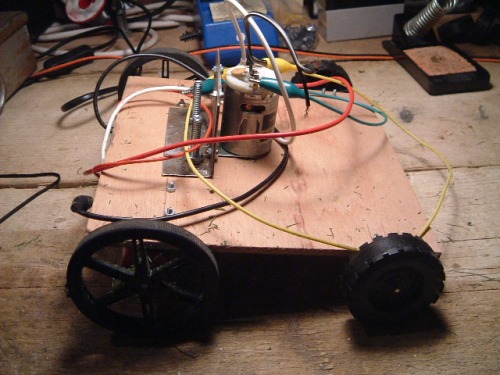
After seeing what model wheels I could find, I determined that a 4cm blade height above the grass was ideal and made a small wooden chassis to achieve this. A few trial runs showed this was rather optimistic on a lawn that is not like a bowling green. Any ruts or irregularities in the ground can cause the mower to ground and dig the blade into the soil so a much higher cut height of 10cm seemed a more realistic value.
This is an image of the prototype used for blade testing
Chassis and Blade Height Revisited
Well, its a year since I have had the opportunity to work on this project so its time to get on with it again. From my previous investigations, I had found a suitable blade arrangement although the chassis and blade height needed revisiting.
I had used a plywood base before but apart from it having the potential to rot, it did not seem suitable for mounting motors etc on and lacked the accuracy of metal. I decided to try a few different plastics as I have not really worked with these materials. The candidates I looked into were:
- HDPE (High Density PolyEthyline)
- PVC
- Perspex
HDPE was the cheapest option. It is very easy to work and has a reasonable flex. It does not glue too easily however. I felt that it was not rigid enough for this application although would be ideal for a smaller indoor robot.
Both PVC and perspex were rigid and were suitable for a platform. I decided to use PVC as it was slightly softer and I know is easy to glue and drill. Hopefully it will be less brittle if exposed to sunlight although I suspect all plastics suffer from that to some extent.
Although a four wheel design may be more stable, a two-wheel + castor design is easier to control and manufacture so I set about designing such a chassis. I have found in the past that a circular design is ideal as the robot can turn in its own footprint. However, in this case I decided to have a chassis with corners as it gave some degree of protection from the cutting blade and there are less obstacles to deal with in a garden compared to an indoor environment.
Wheels revisited
When looking into blade height earlier, I was amazed at how high you need to have the blade from the ground due to ruts and bumps on the lawn. To my eye, the lawn looks relatively flat, it's not a bowling green but when you get your head down to a robot-eye view, it does resemble a grassy moonscape. With this in mind, I decided to go for rather large wheels as these have less chance of getting stuck and also raise the chassis higher off the ground. After looking about, I found Banebot wheels and chose the large 124mm wheels. Banebot wheels have a versatile adaptor for attaching them to motor shafts which also gave some degree of flexibility. A wider wheel also gave more stability and you can even choose how 'grippy' the tyres are!.
The larger wheels gave XXXcm of clearance between the bottom of the chassis and the ground which seemed a good place to start. If I need to, it should be possible to make the blade height adjustable (or even chock the motor mounts) but I'd rather avoid this if I can.
With a larger wheel, for a given motor speed, the robot will go much faster. As a mower has a rotating blade, I'd rather it move much more slowly so you can can see it coming so this requires high gearing. High gearing gives a lot of torque which is a good thing when pushing through grass. By choosing wheel diameter and motor speed/gearing a good compromise can be found.
The new PVC chassis.

Mower Locomotion Speed
The wheels used are 128mm in diameter, so in one revolution they will move pi * 124 = 0.4 metres.
The motor being using (MFA 918D250112/1) has an average (load) speed of 7000 rpm and it is driving a 250:1 gearbox. The geared down speed is therefore 7000/250 = 28 rpm.
This gives a speed over the ground of 28 * 0.4 = 11.2 metres/min or 19 cm/sec so it will take approximately 5 seconds to travel 1 metre.
Bump Switches
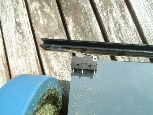
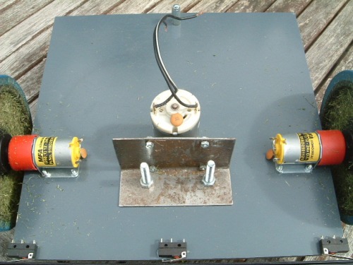
I mounted two microswitches on the chassis, one in each front corner. This allows for the mower to bump into something at an angle and take different action than if it hits head-on. To give it better coverage, a plastic bar was used to attach the two switches as this gives a larger 'touch area'. The connecting bar needed a small amount of flexibility so the two switches were not locked together and could work together without one adversely effecting the other. To cater for the flex, another microswitch was mounted right in the centre so we have a left, right and head-on collision detection.
Hardware
Pinout resources
The propulsion motors will be driven through an H-bridge to allow for easy steering. This will require 4 Arduino pins, two digital and two PWM.
The front bump sensors will be made up of three microswitches, therefore 3 extra digital inputs are required
The main grass cutting motor must be able to be turned on and off which requires an extra digital output
The battery will need to be switched off from the main power drivers. This is either during charging or when the battery voltage becomes too low. One more digital output.
The battery voltage needs to be monitored. An analogue input will be required
If a solar panel is connected, a light sensor may be required. This would use an analogue input.
So this gives a total of:
- 9 digital i/o pins (includes 2 PWM outputs)
- 2 analogue input pins
- Two extra digital pins in remote telemetry is used
- Possibly one more digital output for switching solar panel
- Possibly one or more digital input if rear bump sensors are required
From previous robot experiments, remote telemetry is well worth the effort so you know what the robot is doing. It may also be useful to have several LEDs on the machine itself if pinouts permit.
So this little project needs a lot of digital I/O, at least 11, possibly more. The analogue input requirements are far less so I can always repurpose those if necessary.
Digital hardware
In order to start assigning arduino pins, I decided to start with the H-bridge. I bought one from dfrobotics and that requires digital pins 4,5,6 and 7.
Remote telemetry requires digital pins 1 and 2.
Digital pins 8, 12 and 13 can be used for the bump sensors
Digital pin 10 can be used to switch off the cutting motor.
Digital pin 11 is used to switch a charger to the battery.
This leaves 2 digital pins available (for now)
const int LHF_SW = 12;               // Left Hand Front microswitch (IN)
const int RHF_SW = 13;               // Right hand front microswitch (IN)
const int CF_SW  = 8;                // Centre front microswitch (IN)
const int BATTERY_LEVEL = A0;        // Monitors battery voltage (IN)
const int BLADE_MOTOR = 10;          // cutting blade motor (OUT)
const int CHARGER = 11;              // connect charge sock to battery (OUT)
const int M1_DIR = 7;                // Motor1 direction control (OUT)
const int M1_PWM = 6;                // Motor1 speed control (OUT)
const int M2_DIR = 4;                // Motor2 direction control (OUT)
const int M2_PWM = 5;                // Motor2 speed control (OUT)
Interconnections
Interconnections between the various components will be via single plug/socket headers as used on the arduino initially. I suspect these may vibrate loose eventually in which case I'll replace them with a multi-pin solution after testing the prototype.
Driver Relays
Switching the cutting motor on and off, and isolating the battery involves switching a reasonable amount of current, more than the arduino can source. This can be done via relays or power transistors. For the cutting blade I'm inclined to go for a relay solution as it fails-safe rather than a power transistor which could go closed-circuit if it blows.
It is not difficult to make a relay driver board but I had one left over from a previous project that was 5V operated and could switch 12v at several amps which was more than adequate to turn the cutting motor on-and-off from a digital arduino pin. I will probably use a similar module to toggle the charging circuit once the solar panel is fitted.
Battery Considerations
The blade cutting motor consumes the majority of the power on the mower, when it is spinning the blade, it draws 1 amp. The drive motors and arduino together draw 200mA so under normal operation, let's assume a 1.5A current drain. If the blade were to stall or hit a large clump of long grass, its current consumption would increase dramatically but the the design goal of this mower is to just clip the tops of the grass, so we assume 1.5A current drain is the norm.
Lead Acid Battery
A lead acid battery gives much longer life if it is never drained more than 75% of its capacity. Assuming we need a minimum 1 hour run time, then to leave a 75% reserve would need a 1.5AH/0.25 = 6AH battery, 7AH being the nearest size. The size of such a battery would mean it will not be possible to protect it under the waterproof lid, so it would need to sit on top of the lid. This makes the mower higher and the locomotion motors need to carry the weighty battery, so may have difficulty on an incline
Charging and monitoring a lead-acid battery is very simple, we just need to monitor the battery voltage.
NiMH Battery
Another option is use a string of NiMH AA batteries. 12 batteries would give a 14.4v drive voltage and AA batteries now come with 3AH capacities. NiMH cells can be almost fully discharged so the full 3AH capacity can be used. This means we could get a 2 hour runtime from these cells, equivalent to using a 14AH lead-acid battery weighing 4Kg.
NiMH cells require more complex charging mechanisms, which is compounded by the highly variable output from a solar panel. However, having a microcontroller on-hand will make things easier!
In my arsenal of batteries, I have two lead acid batteries that could be pressed into service, one being 1.2AH, one being 14AH. The 1.2AH battery will give 10 minutes of run time, not really suitable, but small enough to mount under the lid so will be ideal for testing. Once complete, the 1.2AH battery can be replaced. One option is mounting the 14AH lead battery on the lid, or put the NiMH batteries under it. The diagram below gives an indication of the amount of space I have to play with.

There is enough room to fit a 5 watt solar panel onto the mower. 10W would have been better but this would be too large for the mower footprint. In full sun, the specs of the 5W panel state that it can supply 290mA. I will make the assumption that usually we will get rather less than that, say 80mA. Also, being pessimistic, lets say there are only 8 hours of usable sunlight a day which would give 8 * 0.6 = 640mAH per day. For a 3AH cell, we requite approximately 4.5AH of charge (inefficiency) so in the worst case, we need to wait 4.5/0.64 = 7 days to recharge. This seems rather excessive so I feel, for this size of mower, a solar panel is not really practical.
The mower will therefore be charged from the mains using a standard battery charger. This simplifies the charging circuitry considerably and the arduino can monitor the battery voltage and shutdown when it falls below a threshold, to protect the batteries from over-discharge.
Power Distribution
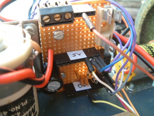
The cutting motor and driver motors require 12-24 volts. The arduino and associated electronics require 5v. A small vero board was constructed that allowed the 12, 5 and ground distribution points to be centralized. The pull-down resistors needed for the bum switches were also included on the board. The main feed from the battery is fused as a 12 volt battery can do a lot of damage if shorted out.
Power Switch and Charger
Without the need for a solar charger, the charging mechanism becomes a socket and a DPST switch, considerably simplifying the design.
Construction
Driving Motors
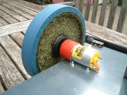
The driver motors were mounted using small 3mm bolts through the PVC chassis. The motors were on top of the chassis to keep them out of all the grass debri that will be generated on the bottom of mower.
Castor
I had a castor from some old furniture. It is perhaps not as heavy duty as I'd have liked, and it may get stuck when reversing but it will do for now. One small mounting hole was drilled at the back of the chassis to accommodate it.
Cutting Motor
A fairly substantial steel bracket was made that allowed the cutting motor to mounted on top of the chassis with the shaft pushed down through a hole in the PVC to where the cutting blade would be. The cutting blade was mounted on a plastic gearwheel and gave a tight interference fit on the shaft.
Battery Mounting
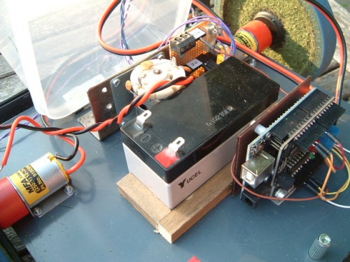
I've never been a fan of glue, I find it does not lend itself to easy dismantling and maintenance and is likely to fail just when you dont want it to. However, in this case, I would like to minimize the number of bolts I put through the chassis as these just form potential collection points for cut grass and could clog the mower. In order to secure the battery from moving around I glued a retaining gutter made of lengths of wood onto the chassis just behind the cutting motor. This keeps most of the weight just behind the drive wheels in the centre of the platform.
Microcontroller stack
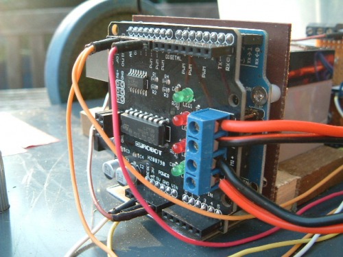
The arduino and motor driver were secured using an aluminium backet mounted just behind the battery. It was mounted to one side to give room from power and USB cables to be attached.
Relay and Distribution Boards
These were mounted on the same steel bracket that was used to hold the cutting motor, just in front of the battery. I may find that vibration from the motor may cause issues later but my goal was to mount al the electronics, the battery and the cutting motor in a central island so they can be covered with a plastic case (onto which a solar panel can be mounted). If vibration does cause a problem, I think I'll move all the electronics into a sealed box with rubberized mounts. However, that is Plan-B.
Weatherproofing
The mower is not really intended to stand outside in all weathers as trying to mow snow or wet grass is probably not a good idea. I do however, want some form of weather proofing so it can withstand cut grass flying around and the occasional shower. This is mainly so it can be left charging on the lawn while I am elsewhere and not have to worry about rescuing it if it starts raining. From the outset, I decided to try and give the battery, the circuit boards and the cutting motor some degree of weatherproofing. The drive motors being close to the wheels will have to look after themselves. The same goes for the microswitches. I have had a small geared motor open to the elements on top of the wendy house for about 5 years and it is still going strong so they should be fairly robust. Mounting a solar panel over the top of the mower should give an extra layer of protection that will also afford some shelter to the motors and switches.
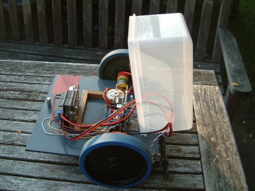
The core components were mounted on an island in the centre of the mower. I used a large plastic box that covers them and hinged it to gain access to the components underneath, passing any wires through one opening near the front of the mower. I'm not going to go banzai over creating a watertight seal, a simple strip of rubber or braid of glue should be sufficient.
Software
The software to drive the mower is fairly straightforward. There are two distinct parts of the code, one that deals with monitoring sensors and taking evasive action if the bump sensors are activated, and one that monitors battery voltage. The main processing loop of the application is thus:
void loop() {
  monitorBattery();
  readBumpSensors();
  process();
}
Where process() will take action on the bump sensor readings if the battery is sufficiently charged. The state of the bump sensors determines the action taken by the mower. If one of the edge switches is activated, it will turn away from that switch (eg, if right switch activated, turn to the left). If either the centre or both edge switched are activated, reverse and turn around. Currently there is no randomness in the turns, a deterministic value is used.
No interrupts are used, just the polling interval of the main loop function which should be perfectly adequate in this application. I spent time making sure the switches were de-bounced in software. I don't really think this is necessary (and it does add a little latency) but it may help false triggering due to electrical noise as there will be three motors in close proximity to the electronics.
Arduino pins used:
const int LHF_SW = 12;               // Left Hand Front microswitch (IN)
const int RHF_SW = 13;               // Right hand front microswitch (IN)
const int CF_SW  = 8;                // Centre front microswitch (IN)
const int BATTERY_LEVEL = A0;        // Monitors battery voltage (IN)
const int BLADE_MOTOR = 10;          // cutting blade motor (OUT)
const int M1_DIR = 7;                // Motor1 direction control (OUT)
const int M1_PWM = 6;                // Motor1 speed control (OUT)
const int M2_DIR = 4;                // Motor2 direction control (OUT)
const int M2_PWM = 5;                // Motor2 speed control (OUT)
Battery Monitoring
A potential divider will be used to bring the battery volt battery voltage down to the 5V range for monitoring. An analogue input to the arduino will monitor this voltage and shutdown if it falls below a minimum threshold.
Having 12 NiMH batteries in series and assuming the max charge per battery = 1.45v and the minimum allowed is 1.0v, we just need to shutdown the motors when battery voltage becomes too low and stay in this state. The mower will then be turned off to allow charging whereupon it will reset.
    /* Assume max charge = 1.45 * 12 = 17.4 volts.
    ** Potential divider = 22k + 82k gives
    ** 33(33+82) = 0.287.
    ** 17.4 * 0.287 = 4.99 volts.
    ** need to shutdown when cell voltage drops to 1v
    ** 1 * 12 = 12 volts.
    ** so 12 * 0.287 = 3.45 volts.
    ** 5v  is represented by 255 in digital.
    ** 3.45/5 * 255 = 176. Therefore this is the digital threshold.
    */
Test Runs
The batteryMonitoring part of the code was disabled (as some hardware had yet to be built) and the mower was taken into the garden for a test run. My 5 year old is very excited building this robot and has suggested it needs painting and must have googley eyes. Obviously these are of upmost importance so I need to get the basic structure working first or it will be very disappointing!
I had removed the switch debouncing from the code as it added latency and I wanted the mower to react the moment when it hit something. I thought this was a safer option although it might mean false triggering in long grass.
The first test was to make sure the navigation was working as expected. I disabled the cutting motor for these tests and found it worked very well, chugging along and turning away whenever it hit an obstacle. The mower did not seem to get caught up in any corners as I thought it may so there may be no need to add any further randomness to its movement. It did get stuck in some large holes left over from some overzealous weeding but there is not really much I can do about that. So all looked good but I did think I may need a higher bump sensor in case it scoots under something. I may see about utilizing the googley eyes for this.
The cutting motor was then switched on and the test repeated. The mower then took on a different personality, spending a lot of time in reverse and randomly turning when on open ground. It was not behaving at all as expected and I put this down to voltage spikes on the power supply. The arduino and motors do share the same 12V supply, and more importantly, the earth. Although I have suppression capacitors across the motor terminals, I think it will be necessary to take some extra precautions.
Back to the Lab
Test run #1 showed I had more work to do. I need to isolate what is causing the arduino to lose its mind. Things to try:
- Extra capacitors between motor terminals and case.
- Replace all motor wires by twisted pairs.
- Add extra reservoir capacitors across the supply.
- Reroute and/or shorten any wires. Maybe use screened wire.
- Try and isolate electronics supply from motor drive supply.
- Possibly screen the cutting motor.
Some of these measures are a quick hit, some involve radical redesign and moving of modules around which I would rather avoid. I tried to route all the wires into the waterproof enclosure through one opening (sensors + driver motors) in order to minimize water ingress and make the hinging of the enclosure simple. However, I think the extra lengths of some cables to reach the opening may be acting as aerials to pick up the cutter mower noise. I'll try and clean the supply up first and then deal with any RF pickup.
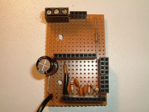
I tried most of the measures above with little success. Eventually I started taking parts of the system away until I isolated the problem. Interestingly, it appeared that it was not a power supply problem, but RF pickup. Once I had stripped most of the wiring away, and even used a separate supply to the arduino, I still found I was having false triggering. It appeared that the wires from the microswitches were picking up noise and passing that into the arduino inputs which cause it to go haywire. I was using 10k pulldown resistors so I tried reducing these to 1k so they were a 'stiffer' ground. No joy. I then found that putting a capacitor across the microswitch contacts did not solve the problem but helped considerably. So in the end I straddled the 10k pulldown resistors with 0.1uF capacitors which removed the offending pickup. I think the lesson learned here is that inputs from sensors need to come in via screened wire but as I did not have any, the capacitor solution would have to do. While I was in there with a soldering iron, I added a 100uF capacitor across the 5v line as well as extra suppression capacitors on the motor itself. The extra capacitors are shown in the photo of the distribution board. Note also the potential divider used to bring the battery voltage range down within the 5v range of the arduino.
Test Run #2
With this hurdle behind me, it is time for another 'field' test, this time with the blades turning. Once this is successful, I'll add the relay switch for the blades and then build the battery monitoring circuit. I've left this until last as it will contain the on/off switch and charging inputs and I need the structure of the mower to be finalized first.
It works ! On short grass, it trundles around as planned. On slightly longer grass, it pushes through and occasionally stops and turns as it hits a grassy tuft. This is still acceptable, the mow pattern just becomes different.
Battery Voltage Monitoring and Charging
NiMH cells can be considered 'flat' when their terminal voltage drops to 1.0v or less. Therefore, when the battery pack voltage drops to 12v (from 14.4v nominal), the power to the cutting motor and drive motors will be cut. The mower will stay in this state until it is recharged.
The on-off switch will double as a charge/run switch. When 'off', current from the charging socket will be routed to the batteries. When 'on', the charge socket will be disconnected and battery voltage will be applied to the mower.
There are few chargers available that will fast charge 12 AA batteries at once and although to build one would not be onerous, my thoughts strayed to power tools. Many power drills have 14.4v battery packs, and come with a fast charger suitable for NiMH or NiCd batteries. I'll see about modifying such a charger or perhaps build one of my own. This also simplifies the lawnmowers charge circuitry, it reduces to a socket and a SPDT switch.
Eventually, I swapped out the lead acid battery for 12 NiMH batteries (2x6) and this gave much better performance.
The Eyes
Now was the time to tidy-up, make the eyes and get the girls to paint the robot to stamp their ownership on it. An extra touch-switch needs wiring in parallel to the centre bump switch and this would be triggered by the eye-stalks hitting an overhanging obstruction. This is needed to prevent the mower diving under a bush and getting stuck on the overhanging branches.
The eye stalks needed to be flexible, springy and capable of making an electrical circuit when they hit something. I considered using feelers that were attached to microswitches but felt they needed to be more robust than this. Eventually, I decided to use net-curtain-rods. There are actually a steel tightly wound spring that is covered in a plastic sheath. Although the steel may corrode over time, they would be easy to replace. The idea is shown in the diagram and I set about making them. The eyes themselves would be ping-pong balls or polystyrene balls, whichever I could get my hands on. The good thing about using the curtain rods is that as they are hollow, it should be possible to run wires down the middle so that LEDs could be mounted in the eyeballs. This is not really relevant for this project but is worth considering for other designs that do not work in full daylight.
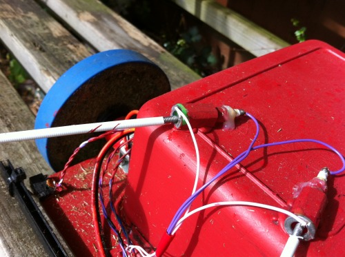
Construction was pretty straightforward. I used parts from a propelling colouring pencil as the base and washers as the second contact. Wires were soldered in place and everything glued together. We shall see how well the glue holds together. The eyeballs will provide some good painting entertainment and by feminizing them with some long eye-lashes, the mower can become a girl :-)
Painting
Painting is naturally the most important part of the whole process and I sat down on the grass with my two girls and let them go mad. It was a messy business but we all had a good time. Each surface had to be a different colour which certainly made painting a tricky business. However, the tupperware lid did not take paint too well and when it dried, some of it flaked off. So we tried again with different paint.
***** Update 20130813 *****
Modifications to the Cutting Motor
The mower is running off 12 x 2900 mAH batteries. This is giving 40 mins runtime, less if the grass is longer. This is not the two hours I was expecting. I notice that when power is low, the locomotion suffers more than the cutting. When I check the batteries once drained, they are very hot so I think I may be overtaxing them. I decided to measure current while mowing and with the blade running, there is a constant drain of 2A, more than my design goal of 1.5. This spikes much higher if Lawna hits a longer patch of grass. Although rated at 2900 mAH I am in fact getting something like 30mins x 2000 = 1000 mAH from the batteries. I could have a faulty cell or the large spikes could be causing the poor performance.
It would be possible to tinker with batteries but I decided to try and reduce the current drain as this is the root cause. The main power hog is the cutting blade. This has a rotational speed of 13000 rpm with a torque of 154 g/cm. It is a powerful 21 watt motor and works well, but at a price.
I originally approached mowing with the idea of having a very fast blade to allow a blunt blade to cut the grass. I decided to rethink this. If I used a slower rotational speed, by the use of gearing, it could be possible to achieve the same torque but using a less power hungry motor. I did source a motor that gave about the same torque which ran at 5000 rpm via gearing. I decided to go one step further and bring the rpms down lower and increase the torque further. This would enable me to increase the blade size slightly and get a larger cutting area.
The motor I chose is a 6 Watt device with a 6:1 gearbox which gives it a torque of 392 g/cm, over twice that of the previous motor and initial testing indicates the total mower current consumption drops to 1 amp from 2 amps using this setup, hopefully which should double my battery life. The 2100 rpm rotation is considerably lower but I did some mowing testing and it looks to work as well as the faster blade, and with more torque. The picture below shows the original 21 Watt motor next to the 6 Watt motor with its red gearbox housing.
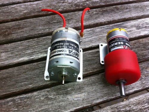
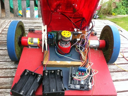
Changing the motor was not too onerous although it did involve a lot of dismantling. Here you can see the fatter gearbox just fits in the space provided and a few changes were needed to the mounting, but these could all be accommodated with the existing brackets. A new blade was manufactured which is 2cm longer than the original. I can make the blade larger but I need to ever mindful of little fingers and with the extra torque this setup has, it could do some serious damage so I've mounted it so it will slip on the shaft if it hits something too solid! The lower speed of rotation does make the mower sound better on the ear as the high pitched whine from the cutter is replaced by a lower frequency drone.
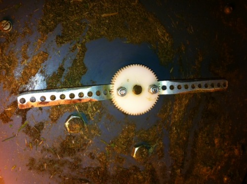
Blades Revisited (again)
The mounting arrangement for the blades is now somewhat different. I used two two disks to hold the blade to give more friction. These need to be drilled with some precision to allow correct alignment. It would be simpler to make the outside disk mounting hole D-shaped like the gearbox shaft but I still wanted some degree of clutching in case the blade hits little fingers.

Rewiring
While I was pulling bits out of the mower, I decided to make some of the wiring more permanent. The arduino is great for prototyping but the round-pin-in-a-square-hole does not make for a reliable and long lasting connection. So far, I have not really had any problems but the vibrations of the mower lend themselves to wires working loose.
A simple solution to the firm-up the wiring was to plug male pcb headers into the female sockets and then makeup female header blocks. These could use square connectors which would make the joints far more secure. In addition, the use of rows of connectors make the connections much more secure, rather than having one wire per socket.
pin 8 - orange (central bump switch)
pin 10 - white (cutting motor relay trigger)
pin 12 - red (left touch switch)
pin 13 - green (right touch switch)
Battery Charging
Although I have built in a charging socket, to date I have been pulling the batteries out to recharge them in my NiMH charger. The reason for this is that there are 12 batteries in series within the mower which means about 17v when fully charged and I don't have a charger that can do that.
I've always quite liked trickle-charging as it means you can leave the batteries connected and be sure they are always fully topped up for when you need them. NiMH batteries lose their charge if left unused, so topping them up is a useful feature. A trickle-charger for a lead acid battery is simple as the battery regulates the charge. For NiMH, you need a constant current source so it is a little more complex and it is recommended that you don't trickle charge them in some texts.
Some more research reveals you can indeed trickle charge NiMH cells, provided the charge current is kept below C/40 where C is the AH rating of the battery. I have 2900mAH batteries which means 2900/40 which is about 70mA max. So it might take a few days to recharge them but its not as though Lawna needs to be out every day. Once or twice a week is ample.
I put together a simple trickle NiMH trickle charger from components in my junk tin which gives a 60mA charge by charging all the cells in series. The power source is a 20V dc small power brick rescued from some broken led christmas lights.

Test Runs with new Cutting Motor
I finally managed to test the new cutting motor. The good news is that the battery life has been dramatically improved, I'm seeing over an hour of mow-time easily although I've not measured the total achievable.
The grass was rather wet during testing and although there seemed to be lots of grass cuttings being ejected from the back of the mower, I was not seeing the narrow strip of mown grass that was apparent with the previous motor. It could be the wet grass, I did not use the old motor on wet grass but I suspect the slower rotational speed means some of the younger grass bends rather than gets sliced. Regardless of how wet the grass is, Lawna should still be able to cope so some changes are needed.
Blades Revisited (Yet Again)
The new cutting motor rotates considerably slower but still at 2000 rpm. It also has twice the torque of its predecessor. If I were to make the blade larger, the tips of the blades would have a much faster linear speed over the ground so I might get back some of the advantages of the original motor. Also, as it has taken me so long to develop this mower, the girls have got quite used to not going near the blades so another option is to grind a sharper edge to aid cutting, especially nearer the hub. If I go down this route, I need to make the foot bumper more robust to ensure it does not come off.
I ground an edge onto the existing blade to see how it fared. The answer is very well :-). Lawna was happily cutting 4cm wet grasss and flinging it out the back. The locomotion wheels struggle in this length of grass as after-all, that is not what the mower was designed for. So a slower blade with more torque required a sharper blade and we get a great battery saving, well over 1.5 hours and still going. I'm hoping that on shorter grass, we will get over two hours. Here is yet another picture of a mower blade !
Foot Bumper Revisited
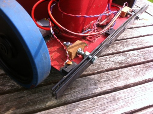
The foot bumper is made up of semi-rigid plastic strip that is attached to two long-arm microswitches. This works pretty well most of the time but it is only held on as strongly as the lever-arms of the microswitches. The bumper can ping off if a branch from a shrub gets under the bumper when the mower is backing away. If I am going to make the blade both larger and sharper, I need to ensure this does not happen.
The chosen solution is to use two bolts through the bumper and mount them on fixed supports. The bolts use compression springs to hold them away from the microswitches. There is therefore no mechanical connection between the bumper and the switches as the bolts and their mountings handle that. There needs to be enough 'slop' so the bumper can activate left, centre or right switches so as to make the appropriate avoidance action. It took a bit of experimentation to find springs that were sufficiently string to hold the bumper rigidly but not too strong to prevent the switches being activated on contact.
It was possible to remove the microswitch levers totally and the bumper is mounted very close to the front of the chassis thereby fixing an earlier issue where twigs could sometimes get caught between the bumper and the chassis when backing out of a bush. I spent 30 minutes directing the mower under one bush after another and it managed to get out of trouble easily, without the bumper getting caught. Here is the idea:
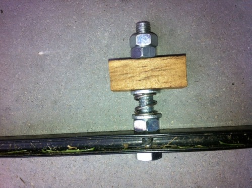
And this picture shows it mounted on the mower. (Yes glue again, but I needed to minimize the number of grass-traps under the mower and bolt-heads are exactly that !
Software Updates
I have not made any software updates for a long time but as the project nears completion, it is time to start adding minor adjustments made by observing the mower's actions and situations where it gets into trouble.
One problem area I see is when Lawna gets stuck in a pothole or hits a horizontal spike that sits above the bump sensor and below the eyes. Currently she will keep going forward, spinning wheels and generally being pretty stupid.
As the mow pattern is already random, a bit more randomness will do no harm. I aim to add a tweak that throws in a random reverse and/or turn every N seconds so that if the mower ever gets in the state of pushing against an immovable object, it will try various exit strategies and hopefully get out of trouble. It will make the normal mowing pattern rather erratic but at least it is planned erratic behaviour, unlike some of my initial test runs!
When, (a long time downstream), I add homing behaviour, I will need to disable this randomness but I think I will need a re-write by then and may turn the whole program into a finite state machine to aid testing.
Results
Changing the cutting motor be a lower power, higher torque variety has increased battery longevity considerably. The slower speed of rotation did effect cutting efficiency but grinding the blade to give it a sharper edge solved that. The sharper blade meant the front bumper needed to be more sturdy and in the process of redesigning it, one area where the mower could get stuck (reversing out from a bush) was also solved.
An fortunate side-effect of the slow rotational speed is a less annoying whine (like a strimmer) coming from the mower, the main noise now comes from the drive wheels.
I'm happy with Lawna as she stands, it is possible to let her loose on the lawn and she trundles around weaving this way and that, dives under bushes and comes out chewing leaves. The battery life is now very good and the trickle charger, breathes life back into the batteries in-place. It's unfortunate that we are now at the end of the summer and a lawnmower is unlikely to be very useful for several months but we are ready for next year!
I'm going to close off this project now and turn my attention at homing and docking mechanisms so Lawna may well get a refit in the future, but that is a job for another day.
September 2013
mows the lawn
- Actuators / output devices: geared motors
- Control method: autonomous
- CPU: arduino 328
- Power source: nimh
- Sensors / input devices: microswitch touch sensors
- Target environment: ourdoor
This is a companion discussion topic for the original entry at https://community.robotshop.com/robots/show/lawna-a-robotic-lawnmower


