Or a cap?
Actually if I use a cap instead of a diode won’t it convert my wave (AC) to DC? I assume I’d need a resistor or two in there as current limiters to keep from blowing either the cap or the transistor.
A cap in series with the
A cap in series with the signal will remove the DC component and only let the AC through. A cap between signal and ground will ‘short’ the AC signal, removing most of it, and letting any DC component pass through. Probably neither will get you exactly what you want.
I’d suggest putting a diode in series like you first suggested, and feed that diode into the positive terminal of a small cap. The positive terminal also connects to your transistor (via a base resistor), and the negative terminal connects to ground.
When the sine wave is present, half the wave gets fed to the cap, charging it up. Eventually the cap voltage is high enough to drive the transistor hard enough to switch the coil. When the sine wave is removed, the cap discharges through the transistor’s base, and after a short duration the cap is too low to keep the coil powered.
If you use a MOSFET instead of an NPN transistor you’ll likely need to add a resistor across the cap terminals to allow it to self-discharge (bleed off) when the sine wave signal is not applied.
High gain transistor highly recommended, as Max suggested a Darlington would make a good choice.
I Swear this part didn’t used to be so hard
I have apparently forgotten everything about circuit design.
I’m having trouble coming up with this circuit. I realized yesterday that I have two output pins from the headphone jack of the phone (of course.) To what do I attach the other wire?
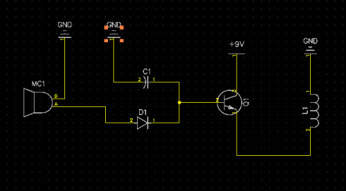
Here is the circuit as I have it so far but It cannot be correct.
Of course.
Yeah, this is what I meant. Of course the current has to be going into the cap at the same time as it is going into the base pin on the transistor. Then when the current from the original source goes away it will flow back out from the cap into the base.
However until I read your description I had the cap wired COMPLETLY wrong. Once you described it, it sunk in.
Now I have a second problem about what to do with the source. I realized I have more than one wire and i’m not 100% sure where to put the other one. hehe, see my other comment.
Can’t you edit your comments?
So I’ve put a mic as the source. it’s really going to be the headphone jack off my old cell phone.
My problem w/ the above schematic is, isn’t the 2nd 1/2 of the sine wave now going to want to flow out MC1’s B through ground into C1’s pin2 and onward?
I believe TF suggested I put a resistor betweek the Cap/Diode pair there and the transistor base.
No wait
What about this.
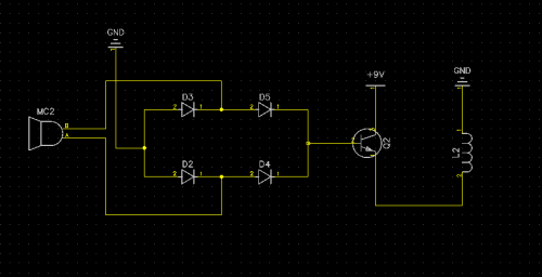
I don’t know how to make DipTrace angle the diodes. That’s supposed to be a bridge rectifier there.
Using the bridge rectifier
Using the bridge rectifier allows for more current to be delivered from the signal line to the transistor, but in this case you’ll still end up with pulsed current through the coil, since the rectifier output will swing through 0V twice for each sine wave period.
You could always combine this with your previous circuit (adding the capacitor to the transistor’s base) to keep the transistor switched on whenever the sine wave is being transmitted.
You might run into a problem with the diode’s forward voltage drop however - compared to the other circuit, the sine wave signal needs to overcome the minimum forward voltage of two diodes instead of just one. Normally this wouldn’t be an issue, but the audio signal is very small, so you’ll have to find/build a bridge rectifier with a low enough forward voltage drop.
Are you going to use a mono (2 contact) or stereo (3 contact) headphone plug? The ring contact nearest the wire is the ground, the other ring and/or tip contacts are for the audio signal itself.
Re: low voltage drop
Are you saying he should look for Germanium diodes to make his bridge then? I have read they have only a .2 to .3v drop vs the .6 to .7v drop of a standard diode.
Yep, germanium diodes have
Yep, germanium diodes have the lowest forward voltage drop of anything widely available that I can think of. At low current the voltage drop will be even less =)
Correction
Your coil needs to be between the collector and + with the emitter going directly to ground. You also need a spike suppression diode accross the coil. I didn’t catch what frequency audio you’re using, but you may need to put a small capacitor, (couple microfared), from base to ground to prevent chatter.
Validation
Thanks for the tips. You just answered several of the questions I was going to ask.
I figured I was going to need a cap in there to smooth it from pulsed DC into solid DC but I wanted to look it up first so I left it out.
I realized just after I created this diagram that I had just designed an AC to DC converter. Now that’s a phrase I can search the googles for and see a number of reference designs. So I figured I would check out some to make sure where I would be putting the cap would be correct. I’ll have a new schematic soon.
The tip on the germainium diodes is great also TY.
New questions.
A friend of mine is speculating that 2600hz might be too fast. That I would have more success at something like 60 specifically because it would give the cap more time to charge. What do you think?
For the hardware I am going to use a stereo jack. I’m actually planning on just cutting the speakers off an old crummy pair of earbuds. I suppose it might be nice to the device if I soldered a resistor across the leads of the one that I’m not using? I know some electronics don’t like generating a charge that doesn’t have anywhere to go.
Moar Better Even
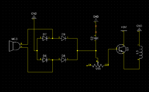
Ok, so here is what I have now. I have added the cap. I have also added a trim pot as a current limiting resistor between the positive output of the rectifier circuit and the transistor for safety though from Telefox’s comments about the voltage drop of the diodes it sounds like having a current limiting resistor is redundant?
I have also seen some of these designs with a resistor, almost always 1k, between the DC output of the bridge rectifier. What I don’t know is: Is this there to represent the load or in addition to the load? Do I need one in this schematic?
I am going to go select some sample components from my parts bins and start playing with this right now.
Let's see if I can do this without letting the smoke out of anything.
Spike suppression
Ah yes, was reading the transistor diagram backwards. I thought I had it connected to + in that diagram. my bad.
What nature of diode do I use for spike surpression and how do I connect it?
I have a cap connected between base and ground but through the trim pot. Though I put it there to smooth the pulsed DC into straight DC.
Can you define ‘chatter?’ You’re talking about spurrious signal leaked from one portion of the circuit to another?
The frequency is completely flexible. Right now I’m sending a 2600hz signal but someone said I might have better luck at 60. Advice?
As a general rule you should
As a general rule you should always have a current limiting resistor connecting the signal to the base of a transistor. Better to have that extra layer of protection even if you may not need it.
The resistor across the bridge rectifier outputs is probably just there to show where the load is connected, don’t worry about adding it in.
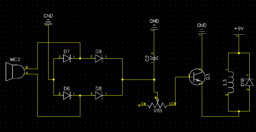
Continuing from Salvage’s suggestion, Q3 in your diagram is an NPN transistor, but it is on the “high side” of the coil (closer to V+). When acting as a switch it’s usually best to put an NPN on the “low side” of the load (closer to GND), either that or switch to a PNP and put it on the high side. Probably just moving the coil between the NPN’s collector and +9V would be best.
The suppression diode Salvage mentioned is usually connected in “reverse parallel” with the coil, which means that the diode is connected to the circuit at the same points as the coil, but the diode is pointing in the reverse direction. Another common name for this sort of diode is a flyback diode - the Wiki page explains the concept quite well.
As for what sort of diode to use, I’d just recommend a common 1N4001, 1N4007, or something else from that family.
Re: bridge rectifier
I started thinking about your circuit again and the input to it. Would you really need a bridge rectifier? You are feeding your circuit a wave that never breaks the ground plane. A bridge rectifier forces the half of a wave form that is negative to become positive. You don’t need that. I would think a cap on the input should smooth out your wave.
PS - I think a lot. I am not always right. 
Like So Then?
I’m familiar with using a flyback diode but for some reason my brain was broken and I wasn’t able to envision where it went. I use them with motors.Thanks for the Schooling.
Why does it matter what side of the coil the transistor is on?
Looks good?
I think I'm going to have to buy some diodes. I went through mine yesterday and I have no Zeners at all, nor do I have the 4ks you mention. I have a whole pile of Zener diodes which is ironic because I didn't have any the last time I was digging around for diodes. ^_^
Thanks for the education all of you.
"Why does it matter what
"Why does it matter what side of the coil the transistor is on?"
The collector-emitter current (which feeds the coil) is related to the base-emitter current, and the base-emitter current is related to the voltage across the base resistor, VR1.
When the voltage stored by C2 is greater than the voltage at the base of Q3, current will flow into the base, turning Q3 on. Q3’s base voltage is always going to be a few hundred mV above Q’s emitter voltage - if the emitter voltage goes up, so does the base voltage.
If Q3’s emitter is connected to GND, it will be fixed at 0V, and therefore the base voltage will be only slightly above 0V, making it fairly easy to turn Q3 on.
In the earlier circuit, the emitter voltage will rise and fall depending on the voltage drop across the coil, L3. The higher the voltage drop across L3, the higher Q3’s base voltage gets, and the harder it is to turn Q3 on. This makes the circuit behaviour a lot more complicated =)
BTW in the diagram you’ve attached above, Q3 is upside-down. The emitter (pin with arrow pointing out) should connect to GND.


