Hi
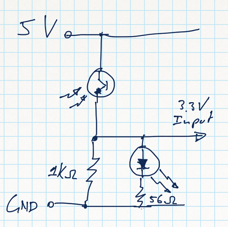
I am using a IR sensor (photo transistor) that was ripped out of a ball mouse and I am running it at 5V, but I need to connect it to a Raspberry Pi which runs at 3.3V (at least the IO-pins are).
I can place a 3.3V regulator before the sensor and adjust the pull down resistors, or use a zener diode to limit the output, but I was wondering wheter my currecnt setup will be safe to use.
Sorry for the poor quality drawing by the way.
I used a potmeter for pulling down the transistor output and adjusted it until a voltage between 0.6 and 2.5 volts are going to the input. It came out at 1K Ohms.
Because the sensor is used as 1 half watcher for an encoder wheel, It takes very small turns of the wheel to measure the output.
To make sure the two sensors don’t turn on and of simlutateously and to visualize the timing, I added an LED and connected it with a small (56Ohm) resistor to ground.
The LEDs blink happily as the encoder wheel spins. You can see them switching on, turning brighter, dimming and switching off. I guess the switching occurs because when the output voltage is below the forward voltage of the LED, no current flows and the LED is off. Above the forward voltage, the LED switches on.
I asume that, because I don’t measure any voltages above 2.5V, this setup will be safe to connect to the Raspberry Pi 3.3V inputs.
Am I correct in this or is it there a risk that unforseen circumstances will still damage the Pi???


