

homesensor.bas (1751Bytes)
homerecv.bas (1811Bytes)
home.py_.txt (961Bytes)
sensor.py_.txt (3321Bytes)
homesensor.png (122989Bytes)
After having read so many interesting posts on the LMR I wanted to make also my contribution. The present project is not a mobile robot but rather an immobile one, the whole house. In the present stage I am just recording the information and on the final one I want my immobot to act e.g. rasing alarms, notify by emails, close/open shutters even regulate the central heating.
I have built a series of wireless sensors based on PICAXE 08M2 and the TX433 module that records temperature, humidity, light intensity, status of doors, shutters, garage door etc. All the information is collected with a receiver based on the RX433 and PICAXE 14M2 which in turn transmits the information to a RASPBERRY PI computer which acts as a data logger and the web interface.
Sensor module:

I’ve tried to minimize the cost of each sensor as well the battery consumption. Each sensor has a unique ID (defined in the program) and it enters in the main loop which does the following (see: homesensor.bas and the PCB layout)
- Sleep for a random period of time up to two minutes. I am using random period in order to avoid interference patterns between sensors. Trying to avoid overlaps of various sensors waking up the same time.
- On wake up it powers the sensors via a BC547 transistor by setting the relative pin to high, and read their values. Two ADC channels and two buttons and calculates a checksum on the values.
- If the checksum of the last reading is different than the previous one then transmit the data. Just for security it transmits the data also after 5 readings anyway.
- To transmit the data, it sends first a repetitive pattern of 101010 bits to wake up the receiver and then try 5 times with the data package. The data are preceeded by a header “HNET”, followed by the raw sensor readings and the checksum. The TX433 module uses amplitude modulation therefore when the data-in is low, it doesn’t consume any power
Power consumption:
During each wake-up it consumes
- Sensor reading 80mA * 1ms
- Transmitting data: 30mA * 4ms
Total: 0.2 mAs = 5.5E-5 mAh
The battery should be about 2500mAh, which gives 45 million readings. On average the period of the reading is 30s, which should give 1000years of operation! However it will die much before since the sleep state consumes some tens of uA and there is an internal drain of the battery. Anyway if it last for a year I will be happy.
Tips:
- I’ve printed the PCB schematic using the supermarket publicity magazine. Transfered to the PCB with the toner transfer method, and Hydroclorone - peroxide for etching.
- I’ve cut in half a DIL08 socket to get two 4-pin sockets one for the TX433 and one for the programming port.
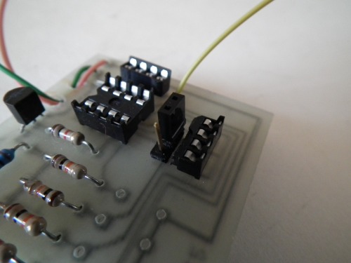
- Using the standard cable/programming port from PICAXE but I've connected the pins facing downwards therefore
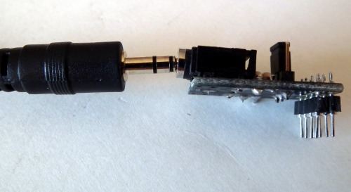
I can insert easily in the half DIL08 and reprogram it at any time. With a small jumper I can use the serin pin as an additional input. The serout pin I use as the data-in for the TX433 module.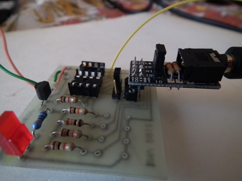
- I've used a 4.5V flat battery with, which I've found as a cheaper solution (1.5EUR alkaline) rather than using 3 x 1.5V AA batteries adding a box and the cable connector.


Receiver module:
I've decided to have an intermediate module as a receiver, rather than connecting the RX433 directly on the Raspberry PI computer. The reasons are the following:
- The Raspberry PI is linux based, therefore not real time and the buffer of the UART is very small. Furthermore the RasPI has small memory and once a heavy application is loaded swaping starts and practically stops any process. Therefore it could lose data
- The GPIO of RasPI is unprotected, so I wanted to have some intermediate protection of the PI using a PICAXE uC
As a uC I've used the PICAXE 14M2 (because I run out of 08M2) and having in mind that in the future I want to be able to control devices in the house. The setup is very simple (presently still on breadboard)

TX433 data-out is directly connected on Pin 1 of the 14M2 and the Pin 2 via a voltage divider (5V -> 3.3V) to the RX of RaspPi
The program uses two threads:
- First is listening the RX433 waiting for the correct data sequence to be send by any of the sensors. Using the checksum to reject unwanted noise, and remove any repetive data. Once it receives a valid packet, it records it on a cycle-buffer in the memory of the 14M2
- The second thread looks the cycle-buffer if something is available and if it finds anything it transmits it to the PICAXE
Tips: The senstivity of the RX433 is proportional to the input voltage. Initially I had the module running on batteries, and once the battery voltage was dropping below 4.3V it was unable to receive data from the far sensors (above 5m)! Now I am using a cheap 5V usb power supply (5 EUR) and it works perfectly.
Raspberry PI:
I am running a custom python script to read the data from the 14M2 and record them in individual files names sensor-$ID.dat for each sensor. All the "advanced" logic happens here e.g. the conversion from temperature-adc reading to Celcius and currently I am working on the Humidity adc reading to humidity percent (a bit more complicated since it requires also the information on temperature).
For the moment I am just recording the data and I have a web interface to monitor the status of the sensors and make graphs with gnuplot


The external sensor I having inside a marmelade jar with holes, which behaves like a green house so the temperature goes to 40C during the day, while in shadow we should have only 20C. I can see the time when my wife cooks in the kitchen, when she opens the windows of the house, lights in the rooms (the sharp lines on the second plot) as well when clouds cover the sun!
