Than you so much for replying. To answer your questions.
I am using atan2 function.
Was there any reason why the Y was chosen -ve upwards ?
In the PEP sheet I have taken the liberty of using it and grabbing some images to emphasize the point
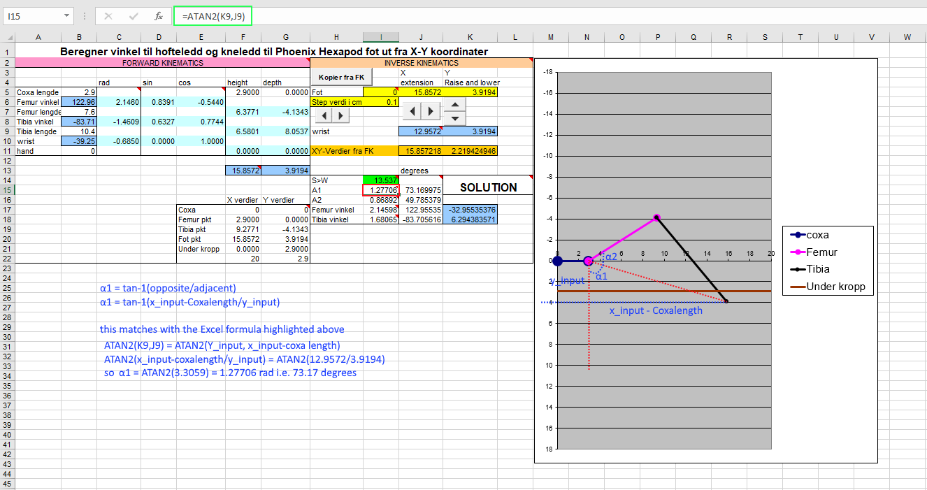
a. For configuration #1 which is the working configuration for me as well the calculations seem straight forward. I have attached the image here.
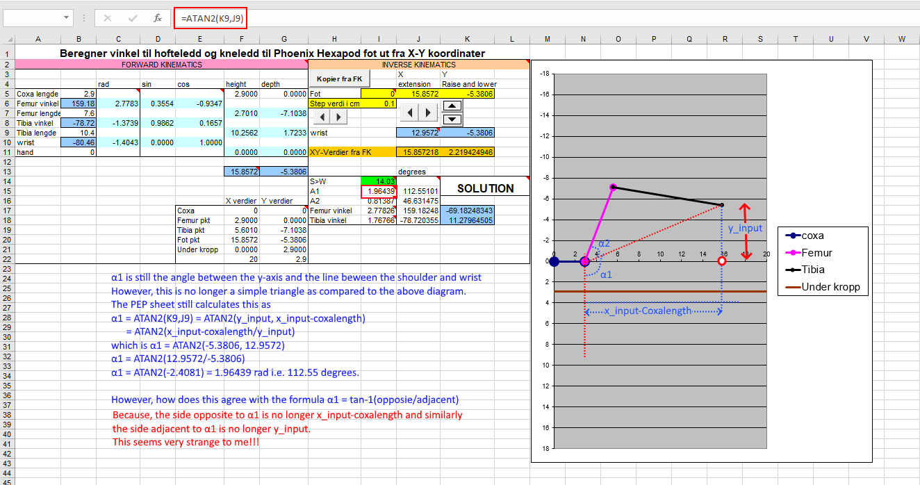
b. For the configuration #2 where the y coordinate changes sign
I have annotated the images to say what I am expecting. For the second configuration there must be some mathematical explanation as to why the ATAN2 is giving out the correct angles despite the formula being incorrect.
Thanks again for your reply. From your first answer I had actually looked at Mike Keeslings spreadsheet and I could work out fine because it is in the standard orientation i.e. y axis +ve upwards.
In fact, the way I have put the axis is origin at the coxa servo and then the +ve y axis upwards i.e. the standard coordinate axis. I started doing it that way and referred to your sheet and that is where it started confusing.
What you said in the third point now makes sense when I calculate it like that. I think what I can’t visualise is the coordinates. What was -ve X before is now the -ve y pointing upwards and the angle is still calculated using the old-x and old-yaxis. However, the co-ordinates of the tip are in the newly rotated axis and that did not fit in my train of thought of considering it as a triangle.
So, if I go by my convention of having the standard coordinate axis i.e. +ve y upwards, do i have to keep track of the y coordinate and change the formula used to calculate the alpha1 angle ?
I had one question for your. Do you also have the axes conventions as per the PEP sheet ? i.e. -ve Y upwards? You seem to have slightly different formula as compared to the PEP sheet.
I wanted to give an update on this post and didn’t want to be one of those lingering post. Thanks a lot to all who helped. My project was boxed up for a year almost due to house moving etc. etc. So this year around late Jan 2021 I got back to it. I wanted to do everything from scratch. I had build my own AVR board form last time when I started working on the hex. The goal was to also do a software PWM controller along with writing the peripheral drivers.
So far I have got the following working
18 channel Timer based software PWM
USART driver for debugging
IK for the legs
PS2 port to C rather than Arduino (bill porter’s library)
Translate body
Rotate body
The axis convention is different than what is in the PEP sheet.
I have attached some pictures of the board that I made.
Also the video of the bot. The cabling needs a bit of tidying up though which I will
However, now that I have managed to get it this far I want to make it walk. I have looked at a few links on how the gait works. Also, looked at this link
I’m not sure what your actual question about Gaits is, so let me start with some basic information that will give you a general understanding of how to read the document in the link.
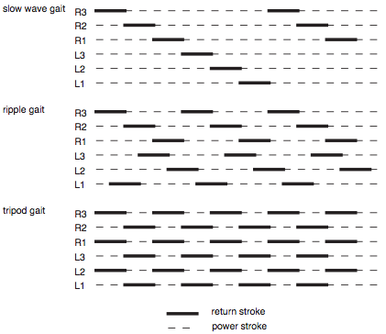
If we talk about gaits, we talk about the sequence of which leg(s) will push the robot forward and which leg(s) swing in the air. Figure 1 shows the sequence of some different gaits where the dark blocks describe the swing in the air to return the leg to the start position. The dotted line describes the time the tip of the leg is on the ground.
Figure 1:
If we look at the first gait, we see that at every given time, only one leg is in the air. All other legs are on the ground. It starts with a swing of leg R3, then R3, etc.
Each gait has different pros, think about speed, stability, force, and style.
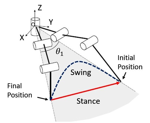
In figure 2, we look at the path made by the tip of the leg. The red line responds to the dotted line displayed in figure 1, where the blue “swing” line represents the return stroke.
Figure 2:
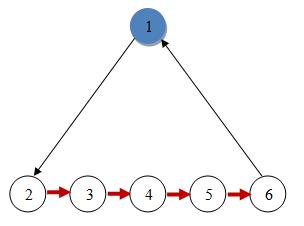
Figure 3 describes how the wave gait is configured in the phoenix code. Each circle in the image can be seen as a position of the tip of the leg. Step 1 is in the air while all other positions will be on the floor.
Figure 3:
Figure 3 responds to leg R3 of figure 1 where the leg starts in the air (pos 1) and then moves down. After that leg R2 will move to the upper position. This means that leg R3, will start at position 1, leg R2 will start at position 6, leg R1 will start at position 5, etc. If all legs move at the next position at the same time, we create the wave gait.
Thank you so much for taking out time to reply! I have been a big fan on the robots been done by you guys here. It is inspiring!!
I will admit that I have seen these diagrams(Figure 1 and Figure 2) before in various places but the way you explained is a lot better.
In figure 2, if I understand this correctly is it the case that the leg from initial coordinates is travelling backwards as part of the swing phase ?
So, if the co-ordinates for my leg i.e. Left Middle leg is X=105 Y = -57, Z = 0
(In my coordinate system Y is the coxa axis i.e. the axis around which the coxa rotates +ve upwards and if you look at it in the top view the X axis the X axis and other is the Z axis )
So in this case does the leg move to Z = -N which is called its final position ? I am only asking because it looks like the initial position is ahead than the final position. However, in my head that does not make sense as then in the stance phase the leg will push the body back wards ?
A few pointed questions:
How do you decide the length of the stance or swing ?
Does this take the rotation in account as well ? How is that done ?
The figure 3 if I understand correctly is it the position diagram of a single leg showing what step positions it goes through ?
The motion (swing + stance) shown in figure 2 describes the same motion as displayed in figure 3.
Figure 2 “Swing” is identical to Figure 3: movement from 6 -> 1 -> 2.
Figure 2 “Stance” is identical to Figure 3: movement from 2 -> 3 -> 4 -> 5 -> 6.
The “initial coordinates” are located on position 4.
The length of the stance is directly controlled by the input from the controller. If the joystick is moved forward, the “travel length” will become larger depending on the analog joystick. At the same time the speed is increased. So if the joystick is moved forward a bit, the travel length is small and the speed is slow. If the joystick is moved forward further, the travel length becomes larger and the speed higher.
The gate in Figure 3 has 4 travel steps on the ground (red arrows) so the travel length is divided by 4. For the swing the length is divided by 2 (black arrows) so the travel length is divided by 2.
The gate in Figure 3 only shows going forward and backwards. But in the phoenix code forward, backward, left, right and rotating can be added all at the same time. Rotating is done using geometric calculations fromt the center of the body to the tip of the leg.
That is great! Thanks a lot for replying ! Does makes things a lot clearer for what is used in the phoenix code. Actually when I was trying to implement my own gait I was thinking of something similar but more like rectangular waveform for the leg tip.
So, basically for tripod gait lift 3 legs up at a height then move a quarter of the total travel distance each time in the air and the remaining 3 legs on the ground move by the same amount but in the opposite direction… I started with it but then I also stumbled upon some interesting usage of sin and cosine to generate gaits. I am experimenting with it. Trying to add my own understanding on top of it. So far I have managed to get tripod gait working with the sin and cos. Will add a few others slowly (work permitting). Here is the video of it.
Thanks a lot !!! Means a lot coming for you! You have been inspiration along with others in this forum. I have done a bit more on that now… the hexapod can rotate while walking but haven’t clicked any video. Got the wave gait working along with Tripod. Its pretty slow but works. I will use this thread to post future updates. Hopefully you will check again!


